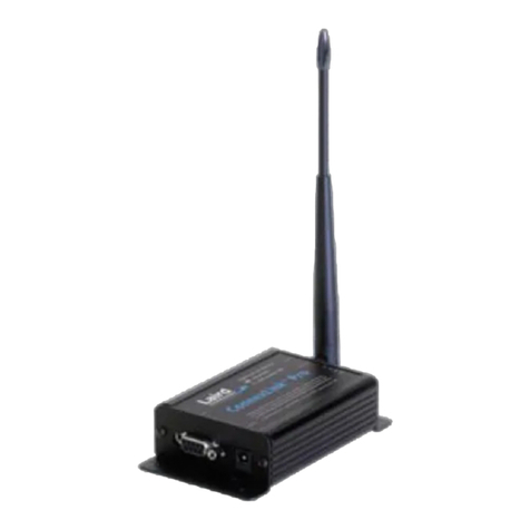
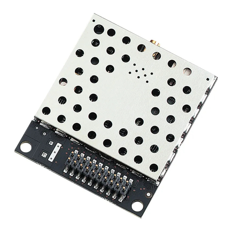
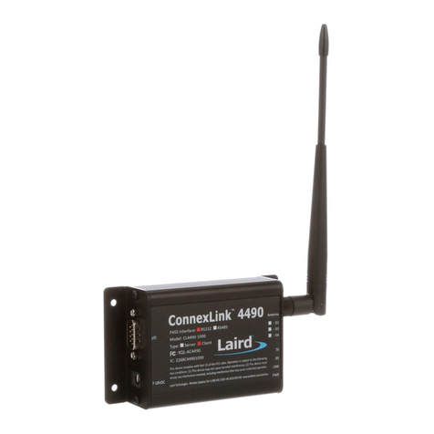
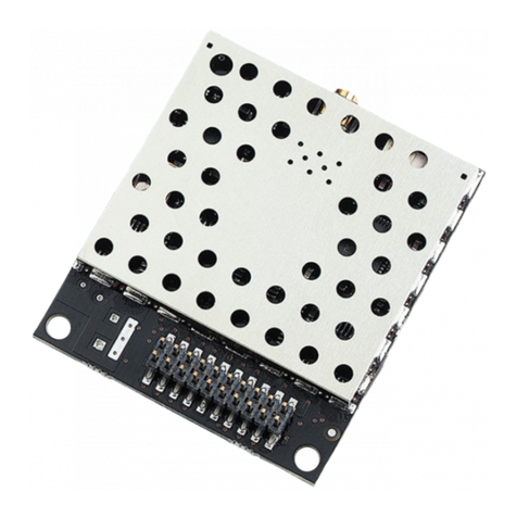
Laird ConnexLink CL2510 User manual

CL2510
RF Transceiver
USER MANUAL
Innovative Technology
for a Connected World
www.lairdtech.com
Version 1.4

Laird Technologies is the world leader in the design and
manufacture of customized, performance-critical products
for wireless and other advanced electronics applications.
solutions for applications in various industries such as:
Network Equipment
Telecommunications
Data Communications
Automotive Electronics
Computers
Aerospace
Military
Medical Equipment
Consumer Electronics
Laird Technologies offers its customers unique
product solutions, dedication to research and
development, as well as a seamless network of
manufacturing and customer support
facilities across the globe.
Copyright © 2011 Laid Technologies, Inc. All rights reserved.
The information contained in this manual and the accompanying software programs are copyrighted and all rights are reserved by Laird Technologies, Inc. Laird Technologies, Inc. reserves the right to make periodic
without the prior consent of an authorized representative of Laird Technologies,Inc. is strictly prohibited.
All brands and product names in this publication are registered trademarks or trademarks of their respective holders.
This material is preliminary
time and without notice. Laird Technologies’ products are intended for use in normal commercial and industrial applications. Applications requiring unusual environmental requirements such as military, medical life-
Limited Warranty, Disclaimer, Limitation of Liability
For a period of one (1) year from the date of purchase by the OEM customer, Laird Technologies warrants the OEM transceiver against defects in materials and workmanship. Laird Technologies will not honor this
warranty (and this warranty will be automatically void) if there has been any (1) tampering, signs of tampering; 2) repair or attempt to repair by anyone other than an Laird Technologies authorized technician. This
warranty does not cover and Laird Technologies will not be liable for, any damage or failure caused by misuse, abuse, acts of God, accidents, electrical irregularity, or other causes beyond Laird Technologies’ control,
As a result of any event, circumstance, action, or abuse beyond the control of Laird Technologies, whether such damages be direct, indirect, consequential, special or otherwise and whether such damages are incurred
by the person to whom this warranty extends or third party. If, after inspection, Laird Technologies’ determines that there is a defect, Laird Technologies will repair or replace the OEM transceiver at their discretion. If
the product is replaced, it may be a new or refurbished product.

www.lairdtech.com
Laird Technologies
CL2510
RF Transceiver
REVISION HISTORY
Revision Description
Version 1.0 02/22/10 - Initial Release Version
Version 1.1 06/02/10 - Updates to images and tables
Version 1.2 07/22/10 - General Updates
Version 1.3 08/11/10 - Update FCC
Version 1.4 06/20/11 - Update CE
REVISION
HISTORY

www.lairdtech.com
Laird Technologies
CL2510
RF Transceiver
CONTENTS
CL2510 RF Transceiver ...................2
CL2510 Key Features ........................... 2
Overview .............................................. 2
Specications ................................3
Detailed Specications ......................... 3
Physical Interfaces ................................ 4
Rear Panel Diagram .............................. 4
Status LEDs .......................................... 4
Front Panel Diagram ............................ 4
RS-232 ................................................. 5
Pin Denitions ...................................... 5
Interfacing to Other RS232
Equipment ........................................... 5
DTE to DCE and DCE to DCE
Interfaces ............................................. 5
Hardware Flow Control ........................ 5
Theory of Operation ......................6
Modes of Operation ............................. 6
Transmit Mode ..................................... 6
Broadcast Packets ................................ 6
Addressed Packets ............................... 6
Command Mode ................................. 6
Network Topologies ............................. 7
Point-to-Point ....................................... 7
Point-to-Multipoint .............................. 7
Other Network Topologies ................... 8
CL2510 Conguration Settings .....9
Mode: Server/Client ............................. 9
Max Power ........................................... 9
RF Channel ........................................... 9
System ID ............................................. 9
Interface Baud ...................................... 9
Transmit Retries .................................... 9
Broadcast Attempts ............................. 9
Full Duplex ........................................... 9
Auto Destination ................................ 10
Broadcast ........................................... 10
Destination Address ........................... 10
Mac Address ...................................... 10
Additional Features ............................ 10
Conguration Utility Software ....11
Installation .......................................... 11
Conguration Software
Overview .....................................12
PC Settings Tab .................................. 12
Congure Tab .................................... 13
Range Test Tab .................................. 17
Terminal/Chat Tab ............................. 19
Command Tab ................................... 20
Troubleshooting and Tips ............22
Troubleshooting ................................. 22
CL2510 Basics and Tips ...................... 22
TABLE OF
CONTENTS

2
www.lairdtech.com
Laird Technologies
CL2510
RF Transceiver
KEY FEATURES
Easy to USE
• Standard male DB-9 DCE RS232
serial interface
• Standard baud rates supported from
1200 to 230,400 bps
• RF data rates of 280kbps or 500kbps,
selectable
• Advanced conguration using
AT commands
The CL2510 transceiver is a frequency-hopping spread spectrum (FHSS) radio designed for license-free operation in
2.4GH ISM band. The radio sustains a standard asynchronous serial data stream between two or more radios out of
the box. Housed in a compact and rugged die-cast enclosure, the radio is equipped to replace thousands of feet of
serial cable.
Networking and Security
• Retries and acknowledgements
• Frequency hopping spread spectrum for
security and interference rejection
• Customizable RF channel and system ID
• Automatic link synchronization
• Low latency and high throughput
OVERVIEW
The CL2510 is available with a male DCE RS-232 interface and 50mW of output power for use in the worldwide
2.4GHz ISM bands.
This document contains information about the hardware and software interface between a Laird Technologies
CL2510 transceiver and an OEM Host. Information includes the theory of operation, specications, interface
denitions, conguration information and mechanical drawings.
Note: Unless mentioned specically by name, the CL2510 modules will be referred to as “radio” or “transceiver”.
Individual naming is used to differentiate product specic features. The host (PC/Microcontroller/Any device to which
the CL2510 module is connected) will be referred to as “OEM Host” or “Host.”
OVERVIEW AND
KEY FEATURES

3
www.lairdtech.com
Laird Technologies
CL2510
RF Transceiver
TABLE 1: CL2510 DETAILED SPECIFICATIONS
INTERFACES
Serial Interface Connector DB-9 Male (RS-232 DCE)
RF Connector RP-SMA Jack
Power Connector Center Positive 2.5 mm Jack.
OPERATIONAL
Network Topologies Point-to-Point, Point-to-Multipoint
Security One byte System ID
Number of Hopping Channels CL2510-050: 43
CL2510-100: 43 or 79, user selectable
Frequency Band 2400 MHz to 2471 MHz
RF Data Rate 280 kbps or 500 kbps, user selectable
RF Technology Frequency Hopping Spread Spectrum
Output Power CL2510-050: 50 mW conducted
CL2510-100: 125 mW conducted
Maximum radiated power (EIRP) 100mW (CE), or 316mW (FCC) depending on
antenna and country of use
Range Line of Sight
(CL2510-050, with 2 dBi Antenna)
Outdoor: 1.5 miles (2.4 km)
Indoor: 790 ft (240 m)
Sensitivity -98 dBm at 280 kbps RF Rate
-94 dBm at 500 kbps RF Rate
Max Power 300 mW
Temperature (Operating) -40°C to 80°C
Temperature (Storage) -50°C to 85°C
PHYSICAL
Dimensions 4.4” x 2.7” x 1.4” inches (11.18 cm x 6.86 cm x 3.56 cm)
Weight 6 oz (170 g)
CERTIFICATIONS
FCC Yes: FCC ID: KQL-CL2510
IC Yes: IC ID: 2268C-CL2510
CE
RoHS Yes
SPECIFICATIONS
CL2510-050: 43
CL2510-100: 43 or 79, user selectable
Outdoor: 1.5miles (2.4km)Indoor: 790ft (240m)

4
www.lairdtech.com
Laird Technologies
CL2510
RF Transceiver
PHYSICAL INTERFACES
The CL2510 supports standard RS-232 protocols with limited ow control. RF output is through a
RP-SMA jack for use with RP-SMA approved antennas (or equivalent).
REAR PANEL:
TABLE 2: STATUS LEDS
LED COLOR DESCRIPTION
Pwr Green On indicates the unit is powered up
Link Red On indicates the radio is capable of establishing a link:
On a Client, the Link LED activates when it is in range of
the Server and receiving the synchronization beacon.
On a Server, the Link LED is always lit.
RXD Green
receiving serial data
TXD Red
transmitting serial data
SPECIFICATIONS
Power ConnectorDB-9 male Connector
1 5
6 9
RPSMA Antenna Connector
Status LEDs
Pwr Link Rx Tx
FRONT PANEL:

5
www.lairdtech.com
Laird Technologies
CL2510
RF Transceiver
SPECIFICATIONS RS-232
RS-232 is a single-ended serial data transmission protocol. The RS-232 signals are represented by
voltage levels with respect to a system common (power/logic ground). The “idle” state (MARK) has
the signal level negative with respect to common and the “active” state (SPACE) has the signal level
positive with respect to the common.
TABLE 3:
DB-9 PIN SIGNAL NAME DESCRIPTION CL2510 FUNCTION
1 DCD Data Carrier Detect Not Connected
2 RXD Receive Data RXD (input)
3 TXD Transmitted Data TXD (output)
4 DSR Data Set Ready Generic Output
5 GND Ground Ground
6 DTR Data Terminal Ready Generic Input
7 CTS Clear to Send CTS (output)
8 RTS Request to Send RTS (input)
9 RI Ring Indicator Not Connected
INTERFACINg TO OTHER RS-232 EqUIPmENT
The CL2510 is a DCE (Data Communications Equipment) device with limited handshaking. Typically
devices like PCs are considered DTE (Data Terminal Equipment) devices while peripheral devices are
classied as DCE. A DCE device can be interfaced to a DTE device using a straight through serial cable.
When interfacing two DCE or two DTE devices together, a null modem cable is required to cross the
respective input and output signals.
DTE TO DCE AND DCE TO DCE INTERFACES
* Design Tip: When using a pair of CL2510s to connect a PC to a peripheral unit, if you previously used a
straight through cable to connect your PC to your peripheral device, you’ll need to use a straight through cable
between the PC and the CL2510 and a null modem cable between the other CL2510 and the peripheral device.
HARDWARE FLOW CONTROL
Flow control refers to the control of data ow between the host and the CL2510. It is the method used to
handle data in the transmit/receive buffer of the CL2510 interface, and determines how data ow between
the host and the CL2510 is throttled. Often in serial communication, one device is capable of sending data
much faster than the other can receive. Flow control allows the slower device to tell the faster device to pause
and resume data transmission. (Flow control CTS and RTS are used by the CL2510 and its Host, locally - NOT
over the air. Therefore, one CL2510 cannot tell the other to slow down or speed up).
The transceiver uses CTS to indicate the state of its input buffer. The OEM host uses RTS to indicate when
it’s able to receive data from the transceiver. When RTS Enable is set on the transceiver, the transceiver will
monitor RTS and will only transmit data out the serial interface when RTS is low. For this reason, the OEM
should not set RTS Enable on the CL2510, unless the OEM host is specically controlling RTS. Leaving RTS
high for too long with RTS Enable set can cause data loss once the transceivers transmit queue lls.
* Design Tip: Can I implement a design using just Txd, Rxd and Gnd (Three-wire Interface)?
Yes. However, it is strongly recommended that your hardware monitor the CTS pin of the radio. CTS is
taken high by the radio when its interface buffer is getting full. Your hardware should stop sending at this
point to avoid a buffer overrun (and subsequent loss of data). You can perform a successful design without
monitoring CTS. However, you need to take into account the amount of latency the radio adds to the system,
any additional latency caused by Transmit Retries or Broadcast Attempts, how often you send data, non-delivery
network timeouts and interface data rate. Polled type networks, where the Server host requests data from the
Client host and the Client host responds, are good candidates for avoiding the use of CTS. This is because no
one transceiver can monopolize the RF link. Asynchronous type networks, where any radio can send to another
radio at any point in time, are much more difcult to implement without the use of CTS.

6
www.lairdtech.com
Laird Technologies
CL2510
RF Transceiver
The CL2510 utilizes a Server-Client conguration to synchronize the frequency hopping of all devices in the
network. The Server transmits a brief beacon immediately after hopping to a new frequency. This beacon
contains information about the network and the hopping pattern. Client radios will synchronize to this beacon
to ensure they are on the same frequency at the same time as the Server. The Client Link LED will light when
the Client is synchronized to the Server.
Each network should consist of only one Server and there should never be two Servers on the same RF
Channel and System ID in the same coverage area. Collocated Servers are permitted, provided the Servers
are on different RF Channels. Additional Servers in the same coverage area will degrade the performance for
all radios. Interference will increase a maximum of 2.3% for each Server added when hopping over 43 hops
and a maximum of 1.2% when hopping over 79 hops. Degradation may be transparent to the end user
depending on the number of retries/attempts and the data rate.
mODES OF OPERATION
The CL2510 has two primary modes of operation:
Transparent Mode
Command Mode
Transmit mode is used to transmit serial data across the RF and Command Mode is used to recongure
the CL2510.
TRANSmIT mODE
All packets sent over the RF are either Broadcast or Addressed (Unicast) packets.
BROADCAST PACKETS
A Broadcast Packet is one that can be received by all eligible receivers on the network. To increase the
reliability of the delivery of Broadcast packets, the transmitting radio will transmit the message the number
of times specied by the Broadcast Attempts. Broadcast Attempts are necessary because Broadcast packets
are not acknowledged by the receiving radio. Therefore, the transmitting radio has no method for guaranteeing
receipt of the message. The default Broadcast Attempts is 3 and more or less may be necessary in different
applications. Increasing Broadcast Attempts will increase the reliability of data at the cost of the overall
throughput potential of the link. The receiving radio will not forward duplicate Broadcast packets on to the
OEM host.
ADDRESSED PACKETS
An Addressed Packet is one that is only sent to a specic transceiver based upon the MAC address of the
destination. Addressed packets are acknowledged by the receiving radio, so additional Transmit Retries will
only be used if necessary. The transmitting radio will retry sending an Addressed Packet until all of the
Transmit Retries have been used or until it receives a successful acknowledgement from the receiving radio.
COmmAND mODE
Command Mode is used to congure the transceiver. To enter Command Mode on the CL2510 the OEM host
must send the AT Enter Command string “AT+++”. Once in Command Mode, all data received by the radio
over the serial interface is interpreted as command data. Data received over the RF interface will be stored in
the TX buffer until Command Mode is exited.
When using the Laird Technologies Conguration Utility, the OEM doesn’t need to worry about entering and
exiting Command Mode, as the software will do that automatically. These details on Command Mode are pro-
vided for OEMs manually conguring the radio.
* Design Tip: Entering Command Mode.
A properly formed Enter AT Command string must be issued when the RX Serial buffer on the radio is empty.
If data is either pre-pended or added to the AT string, the radio will not properly identify it as the AT Enter
Command Mode command and will not enter Command Mode. It is suggested that the OEM host wait a
sufcient period of time between the last data packet and the AT Enter Command Mode. This time varies
depending on the amount of data being sent and the number of retries/attempts congured. Waiting at
least 250ms should be sufcient for most applications.
THEORY OF
OPERATION

7
www.lairdtech.com
Laird Technologies
CL2510
RF Transceiver
NETWORK TOPOLOgIES
Topology refers to the shape of a network or the network’s layout. How different nodes communicate with each other is
determined by the network topology. The CL2510s support a point-to-point and a point-to-multipoint network topology.
The CL2510s do not support multi-hop meshing or any repeater functionality by default.
POINT-TO-POINT
referred to as a wireless bridge, a point-to-point link replaces a single communications cable. It does not matter which node is
the Server and which node is the Client as both nodes will support bidirectional serial data in the same manner.
POINT-TO-mULTIPOINT
Point-to-multipoint systems have one base station, or access point, that controls all communications with all of the other
wireless nodes in the network. This allows for the creation of a wireless network consisting of multiple nodes. In a
Broadcast Packets. The other nodes would be set up as Clients and set up in Addressed Mode (most likely using Auto Destination).
Data received on the Server’s serial interface would be transmitted to all Clients in range. Data received on the Client’s serial
point-to-multipoint network, but all radios would share the same bandwidth over the RF, so as more nodes were added care
should be taken when transmitting data to prevent collisions.
Server
Client
Client
Client
Client
Client
Client
OEM
Host
Server Client
OEM
Host
THEORY OF
OPERATION

8
www.lairdtech.com
Laird Technologies
CL2510
RF Transceiver
In this example, client radios (because of Auto Destination and Auto Channel) will be able to synchronize
with either Server radio. Message communication from the central server will be broadcast out to all clients,
including those connected to the repeater server. Messages from the clients will be sent back addressed to
the central server.
Limitations:
There are some limitations to this setup.
• The addition of the repeaters requires two additional radios which increases the cost of the systems.
• The repeater setup of a client and server must be powered sufciently.
• The antennas of the client and the server in the repeater should be positioned to minimize interference.
For best performance the antennas should be placed more than 10ft from each other.
• There is no way to know if a client is attached to the central server or the repeater server without some
additional AT commands, this makes it difcult to perform addressed mode from the central server.
• There is no way to tell from the RF packet the clients MAC address when a message is received at the
central server, this is because all messages through the repeater will have the repeater client’s MAC address.
• The OEM must add their own layer of addressing into the data stream to address packets.
• There is some additional latency associated with the repeater; this latency is between 20 and 40ms typically.
Server
Central Computer
Client
Client
Client Server Client
Client
Client
Repeater module
consisting of two
Radios
OTHER NETWORK TOPOLOgIES
Repeater networks
Though there is no functionality for a node to automatically forward a message along to another radio,
repeater networks can be setup through the addition of a second Server to provide for additional coverage.
This example of a repeater network would still be useful for a point-to-multipoint network where some of the
nodes are not in range of the primary access point.
In this network topology a CL2510 is setup as a Server to act as the primary access point. All other radios are
congured as clients with auto-channel and auto-destination congured. Each client in range will then receive
every message from the server radio and will respond back with an addressed message to the server. To cover
additional areas, a repeater consisting of two CL2510s connected via a Null Modem cable can be added to
the network. The repeater would consist of one radio set up as a client to the central computer server and
congured identical to the other clients and one radio congured as a server in broadcast mode. Each repeater
server should be on its own RF Channel. Any client radios in range of this new repeater will synchronize to it.
All radios in the network should share the same System ID.
FIgURE: CL2510 NETWORK WITH REPEATER
THEORY OF
OPERATION

9
www.lairdtech.com
Laird Technologies
CL2510
RF Transceiver
The CL2510 has an internal 256 Byte EEPROM which stores system conguration information. This EEPROM
is loaded at startup and contains the networking and addressing information. The EEPROM can be congured
with AT commands manually or through the Laird Technologies Windows Conguration Utility GUI.
Basic Settings include:
mODE: SERVER/CLIENT
Designate the CL2510 network functionality. In each network, there must be only one Server, all other
CL2510s should be programmed as Clients. The number of Clients is not limited, though they all share
the same bandwidth so available throughput must be considered.
mAx POWER
The maximum transmit power of the CL2510. Reducing the transmit power will reduce the amount of
power the radio needs to transmit (current consumption). Reducing the Max Power will also allow radios
to communicate at very short ranges more effectively. At Full Power the radios should be at least 10ft away
from each other to avoid saturation.
TABLE 4:
POWER SETTING CL2510-050 OUTPUT POWER (mW) TYPICAL CL2510-100 OUTPUT POWER (mW) TYPICAL
Full Power 50 mW 125 mW
Half Power 25 mW 50 mW
Quarter Power 12.5 mW 25 mW
Low Power 10 mW 10 mW
*Power levels are approximate and can vary by 20%
RF CHANNEL
The RF Channel is a number that designates the frequency hopping pattern of the CL2510. All CL2510’s hop
over the same frequency range; the RF Channel dictates the order the radios hop through different frequencies.
All radios on the network must have the same RF Channel, unless Auto Channel is enabled on the Clients.
Collocated networks should use different RF Channels to avoid interference.
SYSTEm ID
A number that designates the network identier. All radios must be on the same System ID unless the Clients
are congured with Auto System ID.
INTERFACE BAUD
This denes the baud rate used for communicating with the CL2510 over the serial interface. The RF Baud is
independent of the Interface Baud Rate. The Default baud rate is 115,200 bps. The Interface Baud rate on the
CL2510 must match the host device baud rate.
TRANSmIT RETRIES
This value represents the maximum number of times a packet will be attempted without a successful
acknowledgement. This number is only used for packets sent in Addressed mode. The default value is 3.
Incrementing this value may increase the reliability of a link.
BROADCAST ATTEmPTS
This value represents the number of times a packet will be sent when using Broadcast Packets.
Unlike Transmit Retries, all Broadcast Attempts will be used every time a packet is sent. The default value is 3.
Increasing this value may increase the reliability of a link.
FULL DUPLEx
The CL2510 reserves two data slots per frequency hop for data transmissions. When Full Duplex is enabled,
Servers will only transmit on the rst data slot, thus reserving the second data slot for Clients to transmit.
In networks with a large amount of bidirectional data, Full Duplex will reduce collisions and reduce the need
for additional retries. Full Duplex must be set the same on all radios in the network. Full Duplex only affects the
RF transmission and not to the serial interface.
CL2510
CONFIgURATION
SETTINgS

10
www.lairdtech.com
Laird Technologies
CL2510
RF Transceiver
AUTO DESTINATION
Clients can enable Auto Destination to automatically set them in Addressed mode and address themselves
to the Server. This allows the OEM to program all the Clients with an identical conguration, allowing
communication with a central Server. This is valid for both point-to-point and point-to-multipoint networks.
BROADCAST
Enabling Broadcast will set the transceiver to transmit all information as Broadcast Packets.
DESTINATION ADDRESS
When not using Auto Destination or Broadcast, the OEM needs to congure the specic destination address for
addressed packets. This Destination Address is the MAC address of the intended receiving radio.
mAC ADDRESS
The MAC Address is unique 6 byte address assigned at the factory. It is the address a remote radio should place
in the Destination Address eld to communicate with that radio.
REmOTE I/O
Remote I/O for CTS/RTS and Remote I/O for DSR/DTR allow these pairs of I/O lines to have their states transmit-
ted across the RF and reected on the remote radio. These pairs of I/O lines can then be used to transmit state
information or for additional handshaking information. The I/O states are only transmitted a maximum of once
every 13ms, so these lines cannot be used for serial data.
ADDITIONAL FEATURES
The CL2510 is based on Laird Technologies LT2510 Embedded transceiver. Additional features are available
on the CL2510 including advanced API modes and additional AT Commands. For more information on these
features refer to the LT2510 User Manual.
CL2510
CONFIgURATION
SETTINgS

11
www.lairdtech.com
Laird Technologies
CL2510
RF Transceiver
The software CD included with your programming kit provides a utility for changing the settings on each unit.
The software is compatible with Microsoft®Windows 95, 98, 2000, Me, NT and XP. Windows 7 and Windows
Vista are supported on a limited basis.
INSTALLATION
Locate the OEM software folder on the Laird Technologies Tools & Literature CD and install the
CL2510 Conguration Software. To install the software, run Setup.exe and follow the installation
prompts. During the installation, the software will prompt the user to install the Laird Technologies
USB Driver. It is recommended that the user installs the driver at the same time as the software. The rst
time the software is run, the following message will be displayed:
Click “OK.” The software will attempt to open COM1 of the PC. If there is a conict or the port does not
exist, the software will show the port as unavailable. This error will be displayed when one of the following
conditions exists:
• There is other software running that has control over the COM1 port. Locate this software and shut it
down while running “Laird OEM.exe” software.
• The PC either does not have a COM1 port or the port has been disabled.
CL2510
CONFIgURATION
UTILITY SOFTWARE

12
www.lairdtech.com
Laird Technologies
CL2510
RF Transceiver
PC SETTINgS TAB
The PC Settings tab is shown in the following graphics, as it will appear the rst time the program is run.
Select the Connex2510 in the Product pull-down menu. Doing this will automatically select the default baud rate
of 115200. Use the Find Ports button to search Windows for existing Com Ports. The ports will then be available
in the drop-down for the Port1 Settings. If the desired Com Port is not found, you can manually add it with
the Add Ports button. If the COM port is listed as unavailable, a different COM port can be selected in the Port
pull-down menu. The application can use two serial ports if the Enabled: box is checked under Port 2 settings.
Port 1/Port 2 Options
The application can control up to (2) COM ports, including virtual COM ports, which physically map to USB or
Ethernet ports. The Port pull-down menu allows selection of COM1 through COM16. An error message will be
displayed if a port is selected that is either nonexistent or already occupied by another program. When a port
selection is made, the application will attempt to open the port and list its status as:
• Unavailable/Open/Closed
The Port Status is shown just above the Port pull-down menu and also in the status bar at the bottom of the
screen. The software will only be able to communicate with a radio if the Port Status is Open.
Although menus are shown for Baud Rate, Parity, Handshaking, Data Bits, and Stop Bits, only the Baud Rate,
Parity, and Handshaking menu selections can be changed. This option must be enabled to read and write the
CL2510 EEPROM.
Options
The application also provides the following options:
Save Settings On Exit
When this option is enabled, all changes made to the Settings tab will be automatically loaded the next
time the application is run. Otherwise, any changes made will be discarded.
Read/Write With AT Commands
When this option is enabled, the application will use AT Commands for its read/write EEPROM functions
instead of the standard conguration commands. This option must be enabled to read and write the
CL2510 EEPROM.
Auto Baud
When this option is enabled, the application will scan all available COM Ports using the most common
baud rates, until a radio is found. If no radio is found or the application cannot open the port, an error
message will be reported. The application will only use Auto Baud when prompted by the user after an
unsuccessful read process.
CONFIgURATION
SOFTWARE
OVERVIEW

13
www.lairdtech.com
Laird Technologies
CL2510
RF Transceiver
Auto Archive
When this option is enabled, the application will archive the EEPROM settings for each radio after a
successful write process. Although not required, the application will prompt the user to type a description
of the changes made. Auto Archive can be used to restore the radio to a previously known working
conguration.
Monitor UDP For New Devices
This option is used for legacy ConnexNet products and does not apply to the CL2510.
Status Bar
Located at the bottom of the application window, the status bar gives the state of Port 1, RTS Port 1, CTS
Port 1, Port 2, RTS Port 2, and CTS Port 2 lines. When the text appears black, the current state will be shown.
When the text appears gray, the current state will not be shown. The text shown in the bottom status bar
gives a simplied status of the current, pending software process. The software has no pending process when
“Communications Idle” is shown. On the right side of the status bar a progress bar is maintained to indicate
the progress of longer commands such as a Find Ports or Write Radio.
About Button
The About button can be pressed to determine the revision number of the application and the contact
information for Laird Technologies.
CONFIgURE TAB
The congure tab is used to display the 256 byte EEPROM contents. The screen is able to do this in two formats:
• GUI
• Hexadecimal
The GUI format is the default method of display. The user may change the display by using buttons located in
the lower left corner of the application window. Clicking on the GUI View button will display the data in GUI
format, while clicking on the EEPROM Editor View button will display the data in hexadecimal.
CONFIgURATION
SOFTWARE
OVERVIEW

14
www.lairdtech.com
Laird Technologies
CL2510
RF Transceiver
Read Radio Button
To update the Congure and EEPROM Editor View pages with the EEPROM contents of a radio currently
connected to the proper port on the PC, click the Read Radio button. A successfully read radio will result
in the following message being displayed:
Write Radio Button
After making changes to the controls on the Congure tab, the Write Radio button can be pressed to save
those changes to the radio EEPROM.
Port 1/Port 2 Buttons
When the Port 1 button is depressed, the Write Radio and Read Radio buttons communicate through Port 1.
When the Port 2 button is depressed, the Write Radio and Read Radio buttons communicate through Port 2.
Calc Baud Button
The Baud pull-down menu includes all standard PC baud rates. In some rare cases, a user may want to use a
non-standard baud rate. To do this, the user will need to click on the Calc Baud button. The Calculate Baud
Rate dialog box will appear.
To calculate the settings for a particular baud rate, type that baud rate into the Desired Baud Rate text eld.
If the number in the Desired Baud Rate text eld is ±3% of an acceptable baud rate, the rest of the elds in
the Calculate Baud Rate will automatically populate. If the baud rate is not supported by the radio, the
remaining text elds will continue to display the number 0.
CONFIgURATION
SOFTWARE
OVERVIEW

15
www.lairdtech.com
Laird Technologies
CL2510
RF Transceiver
An example of an acceptable non-standard baud rate being accepted is shown in the following graphic:
Acceptable Baud Rate Found
No Acceptable Baud Rate Found
Clicking the Save button will cause the baud rate shown in the Actual Baud Rate window to be displayed in the
Baud window on the Congure tab of the application. Clicking Cancel will ignore these changes. The Actual
Baud Rate will not always match the Desired Baud Rate. However, the program veries that the Desired Baud
Rate is within 3% of the Actual Baud Rate (as required by the radio).
Hex/Decimal Button
All of the text entry type boxes found on the Congure tab have an indication of whether the value is
presented in Hexadecimal (Hex) or Decimal (Dec). The indication (Hex or Dec) can be clicked to toggle
between Hexadecimal and Decimal notation.
GUI View Button
Clicking the GUI View Button enables a GUI representation of the 256 byte EEPROM contents of the radio.
CONFIgURATION
SOFTWARE
OVERVIEW

16
www.lairdtech.com
Laird Technologies
CL2510
RF Transceiver
EEPROM Editor View Button
Clicking the EEPROM Editor View enables a hexadecimal dump of the full 256 byte EEPROM resident on
the radio. The EEPROM Editor View is shown in the following graphic, as it will appear after a radio has been
successfully read:
Load File Button
This button is used to load a le previously created by this application and can be loaded to restore an EEPROM
to a former state.
Save to File Button
This button is used to save an EEPROM program to a le. This allows for the current state of the EEPROM to be
restored at a later time.
Compare EE Button
The Compare EE button allows you to compare two or more saved EEPROM les. This can be a very useful tool
when analyzing performance of two or more transceivers. An example is shown in the following graphic:
CONFIgURATION
SOFTWARE
OVERVIEW

17
www.lairdtech.com
Laird Technologies
CL2510
RF Transceiver
RANgE TEST TAB
The Range Test tab allows packets of data to be sent between two radios and reports the numbers of successes
and errors. An example is shown in the following graphic:
Test Selection
There are six test options that can be selected. For each of these options, excluding Port 1 Send Only, the DVK
application will perform data verication as part of the test. This means that the application will send specic
data out and the application expects a specic response to that transmission. If it does not get that specic
response, it will report an error.
Important: The ports referred to are Ports for the application, NOT the Windows communication ports.
The available selections are:
• Port 1 -> Port 2 – This test selection is used when two CL2510s are connected to one PC.
This selection is used to send data from the radio connected to Port 1 to the radio connected to Port 2.
• Port 2 -> Port 1 – This test selection is used when two CL2510s are connected to one PC.
This selection is used to send data from the radio connected to Port 2 to the radio connected to Port 1.
• Port 1 <-> Port 2 – This test selection is used when two CL2510s are connected to one PC.
This selection is used to send bidirectional data from both radios connected to the PC.
• Port 1 Send Only – This test selection is used when one CL2510 is connected to a PC. This selection
is used only to send data from the radio connected to Port 1. This would most often be used when
the remote radio is connected to a second PC and is running the Port 1 Receive Only test. There is
no data verication with this option.
• Port 1 Receive Only – This test selection is used when two PCs are being used with two CL2510s.
One CL2510 is connected to each PC. When this selection is made, the radio attached to the port
of PC 1 will be receiving data sent from the radio attached to PC 2, which is set to Port 1 Send Only.
Both PCs should be set up with the same number of bytes in the Create Data eld. Important: The test
on both computers should be initiated at the same time. If this is not done, there may be some errors
reported until the two radios synchronize with each other.
• Port 1 Loopback – This test selection is used with two CL2510s and one PC. The PC will be connected
to one CL2510 and will be running the development software. The second CL2510 will be powered on.
The second CL2510 is set up in loopback mode, using a jumper to connect TX and RX. The radio
attached to PC 1 will transmit data to the remote radio. The remote radio will receive the data and
retransmit it back to the radio attached to PC 1.
CONFIgURATION
SOFTWARE
OVERVIEW
Table of contents
Other Laird Transceiver manuals

Laird
Laird CL4790 Quick setup guide

Laird
Laird CL4490 Quick setup guide

Laird
Laird CL4490 User manual

Laird
Laird AC4490 User manual

Laird
Laird AC4868 User manual

Laird
Laird CL4790 User manual

Laird
Laird AC4490 Quick setup guide

Laird
Laird AC4868-250 User manual

Laird
Laird CL024 User manual

Laird
Laird SDC-EC25N Quick setup guide