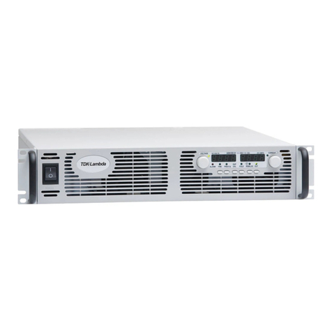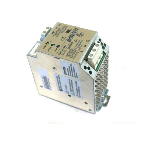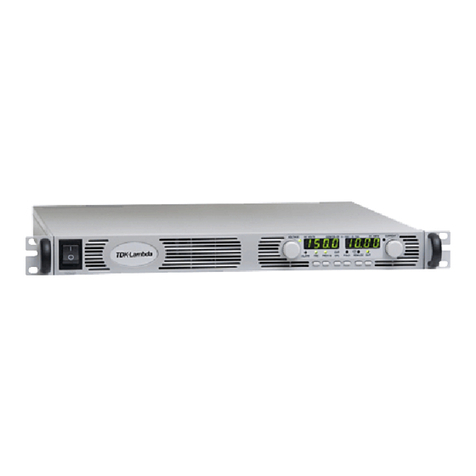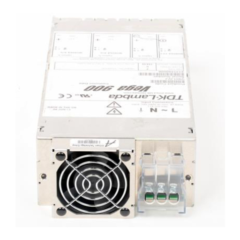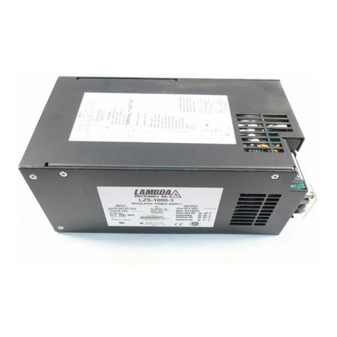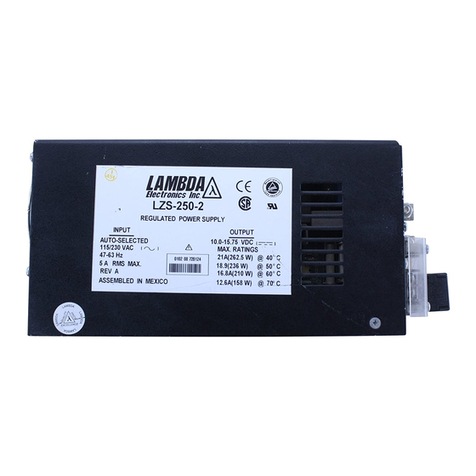
LAMBDA ELECTRONICS SV SERIES
LAMBDA ELECTRONICS, INC. 515 BROAD HOLLOW RD. MELVILLE, NY 11747-3700 (516) 694-4200
PART NUMBER IM-SVPQ1 2
Connector Molex Mating P/N 09-50-8051 AJumper Select 110/220 Vac input
Output and Signals .156" center ZFully Enclosed Unit. 10% for fan cooled
Connector Molex Mating P/N 09-50-8180 All output currents must be derated by: 10% for convection cooled
Mounting 2 Mounting Positions LNo Monitoring Signals
See Outline Drawing 2 Mounting Surfaces Note: See Figure 5 for -N option. Grounding must be provided by customer as shown.
MAIN OUTPUT- V1 SPECIFICATIONS (STANDARD MODELS)
SPECIFICATION CONDITIONS MIN NOM MAX UNITS
Output Voltage (Adjustable) 4.75 55.25 V
Output Current (Power) @ 50°C Ambient 15.0 (75) A (Watts)
Output Current (Power) @ 60°C Ambient 12.8 (64) A (Watts)
Output Ripple 100 mV pk-pk
Total Regulation - Line and Load Over Input Line Range 50 mV
3.8 to 15 A
Pre-Load Requirements(3) 3.8 A
Over Voltage Protection Trip Levels 66.9 V
Turn-on Time 85Vac 2SEC
Overshoot Turn On, Turn Off, or Power Failure 0V
Hold-up Time @ 85 Vac 16 mSEC
Remote Sense (4) Max Cable Drop 0.5 V
OUTPUT- V2 SPECIFICATIONS (STANDARD MODELS)
SPECIFICATION CONDITIONS MIN NOM MAX UNITS
Output Voltage (fixed) Factory Set (5) 11.9 12 12.1 V
Output Current (Power) @ 50°C Ambient 2.5 (30) A (Watts)
Output Current (Power) @ 60°C Ambient 2.1 (26) A (Watts)
Output Ripple 240 mV pk-pk
Pre-Load Requirements 3.8 A on V1 A
Total Regulation - Line and Load Over Input Line Range 600 mV
50% Load Change
Overshoot Turn On, Turn Off, or Power Failure 0V
Peak Output Current See note (6) 7.5 A
OUTPUT- V3 SPECIFICATIONS (STANDARD MODELS)
SPECIFICATION CONDITIONS MIN NOM MAX UNITS
Output Voltage (fixed) Factory Set (5) -11.4 -12 -12.6 V
Output Current (Power) @ 50°C Ambient 0.2 1.0 (12) A (Watts)
Output Current (Power) @ 60°C Ambient 0.2 0.9 (10) A (Watts)
Output Ripple 240 mV pk-pk
Pre-Load Requirements 3.8 A on V1, 0.2 A on V3 A
Total Regulation - Line and Load Input Line Range, 0.2 - 1A Load 600 mV
50% Load Change, 0.2 - 1A Load
Overshoot Turn On, Turn Off, or Power Failure 0V
Peak Output Current See note (6) 3A
(3) 3.8 Amps required on V1 for proper regulation of auxiliaries.
(4) Remote sensing on the main output is accomplished by removing JP2 and JP3 from the printed circuit board and connecting the load to the +S1 and -
S1 terminals found on J2. The maximum cable drop is 0.5 volts.
(5) Minimum load on V1 and no load on auxiliaries.
(6) Peak output current lasting less than 30 seconds with a duty cycle of < 5%. During peak current transients the outputs may not meet regulation
specifications. Multiple outputs delivering peak currents may cause the power supply to current limit.
OUTPUT- V4 SPECIFICATIONS (STANDARD SVPQ130-1 and SVPQ130-2 MODELS)
SPECIFICATION CONDITIONS MIN NOM MAX UNITS
Output Voltage (-1) Factory Set 22.8 24 25.2 V
Output Voltage (-2) Factory Set -4.75 -5 -5.25 V
Output Current (Power) (-1) @ 50°C Ambient 0.8 (19) A (Watts)
Output Current (Power) (-2) (7) @ 50°C Ambient 1.5 (7.5) A (Watts)
Output Current (Power) (-1) @ 60°C Ambient 0.7 (16) A (Watts)
Output Current (Power) (-2) (7) @ 60°C Ambient 1.3(6.8) A (Watts)
Output Ripple (-1) 480 mV pk-pk
Output Ripple (-2) 100 mV pk-pk
Downloaded from Arrow.com.Downloaded from Arrow.com.
