Lampert MEZZO User manual

OPERATING INSTRUCTIONS
MEZZO
Welding microscope with LED-Lighting
For using with PUK 3s welding devices
Dear Customer
This manual will explain the operating principles and correct maintenance of your “mezzo”.
The “mezzo” is a microscope that has been specially modified to suit the here described
applications and uses. Lamperts stereo microscopes are precision instruments that
undergo intensive testing prior to delivery, to ensure that they reach you in perfect
condition. The design allows simple handling, needs only a minimum of maintenance and
at the same time offers outstanding functionality.
Please read this manual carefully and clearly observe the guidelines it describes; this way
malfunctions and operating errors can be avoided. Adhering to the guidelines will promote
the working life of the machine and assure that it remains in constant operational
readiness during this time; it will also ensure your personal safety.
This device may only be operated by qualified personnel, and then only for its
designated use and in accordance with the guidelines here within. The
manufacturer accepts no responsibility, and is in no way liable for damage caused
by improper use or operation of the machine. Before first using your “mezzo”,
please be sure to carefully read the manual sections “General Safety Requirements”
and “Personal safety”.
Please retain these instructions for future reference.
A note on conformity marks
The equipment made by “Lampert Werktechnik GmbH”, fulfils the conformity requirements
of CE certification and is manufactured according to VDE guidelines.
The LCD-shutters used for this microscope have been tested and authorised, and carry
the DIN-CERTCO certification from the DIN authority for eye protection.
When overhauling or reconditioning our devices, we strongly advise only to use original
parts. Our customer service team is at your disposal, and will gladly assist in any way they
can.
The device may only be opened, or alterations carried out, by authorised customer
service technicians. Non-compliance will result in all warrantees and liability claims
becoming void.
LAMPERT WERKTECHNIK GmbH
February 2010

2
TABLE OF CONTENTS
SECTION
A
SYMBOL USAGE 3
1
FIELD OF APPLICATION 3
2
INTRODUCTION 3
3
SAFETY RULES
3-1
GENERAL SAFETY RULES 4
3-2
PERSONAL BODY PROTECTION AND DANGERS 4
4
INSTALLATION
4-1
UNPACKING 5
4-2
ASSEMBLY AND START-UP 5
4-3
DESCRIPTION OF THE OPERATING ELEMENTS 6
5
INSTRUCTIONS
5-1
FIRST STEPS 7
5-2
SETTING THE VIEWING DISTANCE 7
5-3
FOCUSSING 7
5-4
DIOPTRE SETTINGS 8
6
CARE AND MAINTENENCE
6-1
MAINTENANCE OF THE OPTICAL COMPONENTS 8
6-2
MAINTENANCE OF THE ELECTRICAL COMPONENTS 9
7
TROUBLE SHOOTING
7-1
PROBLEMS WITH ELECTRICAL COMPONENTS 9
7-2
IMAGE QUALITY 9
7-3
PROBLEMS WITH MECHANICAL COMPONENTS 9
7-4
REPAIR 10
7-5
TRANSPORT THE MICROSCOPE 10
8
TECHNICAL DATA 10
8-1
TECHNICAL DATA MICROSCOPE 10
8-2
OPTICAL DATA MICROSCOPE 10
8-3
TECHNICAL DATA LCD-SHUTTER 10
9
EG-CONFORMITY DECLARATION 11

3
A SYMBOL USAGE
Warning!
“Warning!” indicates a potentially hazardous situation which, if not avoided, could result
in death or serious injury. This signal word is not used for property damage hazards
unless personal injury risk appropriate to this level is also involved.
Caution!
“Caution!” indicates a potentially hazardous situation which, if not avoided, may result in
minor or moderate injury. It may also be used to alert against unsafe practices that may
cause property damage.
Note!
“Note!” indicates a situation which implies a risk of impaired welding result and damage
to the equipment.
Important!
“Important!” indicates practical hints and other useful special-information. It is no signal
word for a harmful or dangerous situation.
1 GENERAL APPLICATION
The observation or microscoping of objects via the microscope eyepiece and work area
illumination.
The MEZZO may only be used together with the „PUK“-Precision Welding Device.
The MEZZO may only be used if set up according to the instructions.
Any usage other than herein specified is prohibited.
Operation in outdoor areas is prohibited. Use in dry room areas only.
2 INTRODUCTION
Arc Welding without protective equipment is dangerous and may result in a painful
inflammation of the cornea as well as irreversible cataracts. The MEZZO with integrated
LCD eye-protecting filter offers reliable shield against these hazards and permanently
protects the eyes from UV/IR-Rays, sparks and splashes in both its clear setting
(Luminescence DIN3) to its dark setting (Obscurity DIN11). The protection level of the
filter is constructed in such a way, that a dazzling from the glare of the electric arc is
avoided. The MEZZO may only be used in conjunction with PUK welding devices. Shortly
before ignition of the electric arc, the PUK's electronic control unit automatically activates
the filter and switches from its clear setting (Luminescence DIN3) to its dark setting
(Obscurity DIN11). The filter then lightens up again immediately after the electric arc
ceases.

4
3
GENERAL SAFETY INSTRUCTIONS - READ BEFORE USING
3-1 GENERAL SAFETY RULES
A professional may only open the device. Remove the power plug and make sure the
device is not under live power. Always contact your professional if you are uncertain.
Before exchanging the LED module, remove the power supply plug. Only use original
replacement LED modules from Lampert.
It is illegal for non-professional electricians to handle parts that are directly connected to
the mains power supply, except in cases of pulling the mains plug and/or operating the
main power switch.
The device must be disconnected from the mains as soon as repair or service works is
needed. When leaving the place of work even for a short time, make sure that the
electrical outlet is blocked clearly.
If you believe that operating the device is not possible without creating hazardous
conditions, then shut off the device and secure it against unauthorised use.
It is clear that a hazardous conditions are present when:
- the device shows visible damage,or
- or when functional errors occur
- if it no longer functions properly.
3-2 PERSONAL BODY PROTECTION AND DANGERS
EYE PROTECTION DURING WELDING
Do not look into arc without protecting your eyes. Use only a welders’ face
protection shield with protecting glass that conforms to regulation (minimum
protection level 11).
The arc releases not only light and heat causing blindness or burning but also emits UV
rays. If insufficient protection is used, the UV beams can cause very painful conjunctivital
inflammation only noticeable after several hours.
Bystanders close to the arcs also should be made aware of possible dangerous
conditions and should wear protective equipment. If necessary protective walls should be
set up.
EYE PROTECTION WHILST OPPERATING THE LED LAMP
Do not look into the LED Lamp, or into the reflection of the LED light, without eye
protection. Always use a welders’ protective glare shield with a minimum
protection class of 3.

5
4 INSTALLATION
4-1 UNPACKING
All components of the stereo microscope are carefully packed, ensuring delivery in an
immaculate condition. We recommend to keep the packaging material, as it is used for
sending in the microscope or storing it for a longer period of time or transporting it to a
technical service team.
The MEZZO packaging contains the following components:
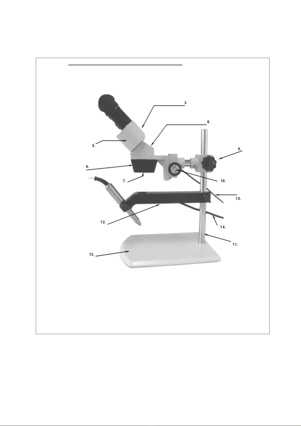
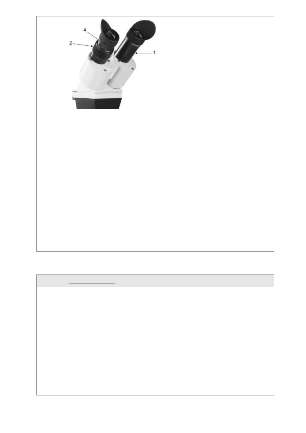
Microscope head with mount and LCD glare protection filter (4.2 Fig.1 - 10)
Two eyepieces with eyepiece covers (4.2 Fig. 2 - 1)
Supporting arm (for holding the welding hand-piece), with integrated LED light (4.2
Fig.12)
Bearing rod (4.2 Fig.1 -11)
Base plate, for attaching the bearing rod (4.2 Fig.1 -13)
Protective cover
Tools for adjusting the focussing levels
Remove and handle all microscope components with great care.
Avoid touching the lenses and optical elements. Also avoid contact with dust, water and
other polluting substances, as they soil or damage the lense surfaces and influence the
quality of the view.
ASSEMBLY AND START-UP
Please perform all work stages involved with the assembly of the stereo
microscope very carefully. The stereo microscope’s individual parts and elements
should not be assembled too forcefully.
Mount the bearing rod (11) to the base plate (13) with the attachment screw and place it
upright onto an even, safe and clean surface
Slide the supporting arm (12) over the bearing rod (11) and secure it slightly above the
middle of the rod, tightening hand tight.
Slide the microscope head (8) and its mount with retaining screw (9) over the bearing rod
(11), and secure it at about 5cm above the supporting arm for the hand-piece (12).
Insert eyepieces (1) and eyepiece covers and secure with locking screw (4)
Connect the control line (15) to the eye protection filter (shutter) (6) with the welding
device (note welding device instructions!)
Connect the LED light with the PUK 3s .
Insert the mains cable (16) into the connection socket marked “LED-Lamp 800 mA”, on
the back of the welding device.
Note!
Always test that the eye protection system (shutter) is in correct functioning order
before you start welding.
Through a press on the output power regulator of the welding device "PUK 3s",
you switch the eye protection filter from bright to dark.
If the eye protection filter (Shutter) does not switch from bright to dark, it must
immediately be replaced.

6
4-2 DESCRIPTION OF THE OPERATING ELEMENTS
(fig. 1)

7
(1)
Eyepiece
(2)
Dioptre settings
(3)
Eyepiece tubes
(4)
Locking screw
(5)
Prism casing
(6)
Eye protection filter (shutter)
(7)
Protective glass
(8)
Head
(9)
Head mount screw
(10)
Focus knob
(11)
Bearing rod
(12)
Mounting for hand piece with integrated LED-lighting.
(13)
Base plate
(14)
Mains cable with plug and switch
(15)
Shutter control line
5 INSTRUCTIONS
FIRST STEPS
Align the tool holder support in such a way that a workpiece can easily, by hand, be lead
to the tip of a mounted tool holder. Both hands or heels of the hand should be able to
easily bear on the base plate.
Switch on the main lighting switch (16).
SETTING THE VIEWING DISTANCE
Look through the eyepieces (1) and move the eyepiece tubes (3) by holding the prism
casing (5) and moving inwards or outwards.
The distance is correct once the field of view can be clearly seen through both eyepieces
and both views combine into a single field of view.
The eye viewing distance should be set individually for each user.

8
FOCUSSING
Mount a welding tool holder to the fixation arm with clamped electrode.
Turn the focus knob (10) to a medium enlargement setting.
Adjust the mounting height of the microscope head:
Hold the microscope head (8) with one hand without touching the lens and, with the other
hand, loosen the screw (9) of the head mount. The head can now be moved.
Look through the eyepieces and move the head up and down until the object seems to
be in focus.
Tighten the screw of the head mount again.
Adjust focus with the focus knob (10).
DIOPTRE SETTINGS
The rings for dioptre setting (2) are located on the eyepiece tubes (3). In the normal
position, the lower part of the sleeve is aligned with the marking on the eyepiece tube.
In case of eyesight deviations:
Only open the right eye, look through the right eyepiece (1) and set the focus using the
focus knob (10).
Then look through the left eyepiece with your left eye and adjust the focus by turning the
dioptre control (2) on the left tube (3) until the view is in focus.
6 CARE AND MAINTENENCE
The mezzo needs, under ordinary working conditions, only minimal care and
maintenance. Remembering a couple of points is crucial, though, to ensure proper
functioning and a long life for your welding device.
After the work is complete, cover device with the dust cover.
Regularly check the power plug, power cable and connector plug for damage.
Clean the device occasionally with a soft cloth or compressed air
CONTACT YOUR DEALER IF MAINTENANCE OR REPAIRS ARE NEEDED THAT ARE
NOT DESCRIBED IN THIS MANUAL
6-1 MAINTENANCE OF THE OPTICAL COMPONENTS
Do not try to disassemble the optical components. Please turn to your local technical
support centre for repairs not described in this manual.
Remove dust particles with a special brush or with compressed air before cleaning the
lens surface. The respective accessories can be found in every photo shop.
Cleaning the eyepieces
Do not remove the eyepieces (1) from the eyepiece tubes (3).
Clean the outer surfaces and breathe on them while doing so.
Subsequently, dry the lens using an appropriate paper or cloth. Dry the lens with circular
movements, starting in the centre and working your way outwards. Avoid wiping a lens
that is already dry, as it might easily be scratched.

9
Cleaning and switching the protective glass of the eye protection filter.
Never dismantle the eye protection filter (shutter)!
Only clean the surface. Use a soft cloth dampened with a glass cleaner.
If protective glass (7) needs to be replaced, push it forwards out of its support and insert
the new protective glass in the same way.
6-2 MAINTENANCE OF THE ELECTRICAL COMPONENTS
Warning! Danger of glare, never look directly into the LED light or its reflections!
Caution! Only operate the LED light when the LED module is mounted in the
supporting arm of the hand-piece.
Changing the LED light module:
Switch the PUK off and remove the power cable of the mezzo from the PUK.
Loosen the retaining screws that hold the LED module, and remove the module.
Only use replacement LED modules from Lampert Company.
Mount the new LED module in the supporting arm of the hand-piece. Remember that the
module should fit flush with the underside of the supporting arm.
7TROUBLE SHOOTING
PROBLEM CAUSE SOLUTION
7-1
PROBLEMS WITH ELECTRICAL COMPONENTS
A
The LED light doesn’t
work
Cord switch is not switched
on
Insert the mains cable (16)
into the connection socket
marked “LED-Lamp 800
mA”, on the back of the
welding device
Cable not attached. Switch on the cord switch
LED defective Change the LED module
(Chapter 6-2)
B
Shutter doesn’t switch to
its dark setting
Control lead is not attached Attach the control lead for
the Shutter (17) to the back
of the welding device
Shutter defective Exchange the shutter
7-2
IMAGE QUALITY
D
Poor resolution. Eyepieces soiled. Clean eyepiece
E
Marks or contamination in
the visual field
Eyepieces soiled. Clean eyepiece
Protecting glass soiled. Clean or change protecting
glass
* Note: Marks in the visual field can also be caused by
contamination inside the eyepieces. It is recommended to
have the lenses cleaned by an authorized service
technician.

10
7-3
PROBLEMS WITH MECHANICAL COMPONENTS
F
Focusing does not remain
7-4 REPAIR
If the stereomicroscope must be repaired or revised by technical personnel, we
recommend, to send it back in its original packaging to the dealer. Attach a description of
the problem or the desired revision.
WARNING! Authorized personnel may only open the device!
7-5 TRANSPORT THE MICROSCOPE
If possible avoid to move the stereomicroscope.
Carry the stereomicroscope with both hands. With one hand hold on to the tripod rod (11)
of the stereomicroscope, with the other hand hold on to the base plate (13).
Keep the stereomicroscope always upright.
8 TECHNICAL DATA
8-1 TECHNICAL DATA MICROSCOPE
■
Optical view protection and illumination unit (welding shield) only
to be operated with the PUK 3-Precision welding device
■
Use only in dry environments
■
Operating temperature +5°C bis +40°C
■
Bulb “LED-module” 2,5W / 800mA
■
Protection class III
■
Insulation class B
■
Type of protection IP 20
■
Weight 3,7 Kg
8-2
OPTICAL DATA MICROSCOPE
■
Lens 1,0
■
Eyepiece 10x
■
Work distance 140 mm
■
Enlargement factor 10x
■
Field of view 20 mm
8-3
TECHNICAL DATA LCD-SHUTTER
■
Brightness level DIN 3
■
Darkness level DIN 11
■
Circuit time <50ms
■
UV Protection >UV 15
■
IR Protection >IR 14

11
WARNING!
Authorized personnel may only open the device!
Text and images correspond to the technical version during print of this manual. We
reserve the right to change components.
9 EG-CONFORMITY DECLARATION
The Manufacturer,
Lampert Werktechnik GmbH
Ettlebener Str. 27, 97440 Werneck, Germany,
declares that the product
Welding microscope with eye protection system
MEZZO
conforms to the conditions set forth in the below-named guidelines, including any
changes made up to the time of declaration.
Relevant EEC guidelines:
According to low voltage guidelines 2006/95/EG
According to EMV (electro-magnetic compatibility) guidelines 2004/108/EG
The following harmonised standards were used:
EN 60974-6
EN ISO 12100-1
EN ISO 12100-2
DIN EN 169
DIN EN 379
Person duly responsible for technical documentation: Hammer N.
Werneck, February 2010
Lampert Werktechnik GmbH
Andrea Bauer-Lampert (President and CEO)
Table of contents
Popular Welding Accessories manuals by other brands

Abicor Binzel
Abicor Binzel MB EVO PRO operating instructions

Amada
Amada WELD CHECKER MM-400B Operation manual

Lincoln Electric
Lincoln Electric Lincolnweld 780 datasheet

Weller
Weller WTA 50 operating instructions

Elektra Beckum
Elektra Beckum Welding Transformers and Rectifiers SB 160 C operating instructions

Miller Electric
Miller Electric D-74DX owner's manual

Kemper
Kemper 1047 user manual

Topex
Topex 82S211 instruction manual

Abicor Binzel
Abicor Binzel ABIMIG operating instructions

Miller Electric
Miller Electric Roughneck C-Series Specifications

Helvi
Helvi VISION 4.1 instruction manual

Lincoln Electric
Lincoln Electric WIRE FEED MODULE IM 513-B Operator's manual