Lanair DUCTABLE DHI-300 User manual

DHI-300
DUCTABLE
WASTE OIL HEATER
Installation andOperating
Instructions
Lanair Waste Oil Heaters & Boilers
4109 Capital Circle
Janesville, Wisconsin 53546
608-752-1601
www.lanair.com
Lanair Waste Oil Heaters & Boilers
4109 Capital Circle
Janesville, Wisconsin 53546
608-752-1601
www.lanair.com
© 2006 Martrade LLC Lanair is a registered trademark o Martrade LLC P/N L44
REVISED 1-06
Listed MH 14518 (N)

BEFORE YOU BEGIN INS ALLA ION...
IMPORTANT
Read and understand this manual completely before beginning installation.
• This heater is for commercial and industrial use only. This unit is not intended for residential
use.
•This heater must be installed and/or inspected by a licensed heating contractor
before operation. Installer should be trained and thoroughly familiar with the
installation and operation of oil-fired heaters.
• Installation of this unit must be made in accordance with state and local codes or authori-
ties having jurisdiction over environmental control, fuel, fire and electrical safety.
• N.F.P.A. (National Fire Protection Association Publications for Heater Installation)
NFPA No. 30 Flammable and Combustible Liquids Code
NFPA No. 31 Standard for the Installation of Oil Burning quipment
NFPA No. 70 National lectric Code
NFPA No. 80 A&B Repair Garages and Parking Structures
NFPA No. 211 Standard for Chimneys, Fireplaces, Vents, and
Solid Fuel Burning Appliances
The above standards are available from the National Fire Protection Assn., Battery March
Park, Quincey, MA 02269
• Read and familiarize yourself with these instructions and associated photos, diagrams and
illustrations before beginning installation or operation.These instructions should be fol-
lowed closely, to achieve the best possible results.
If you have questions or concerns at any time during the installation, stop the installation
and contact a Lanair Service Representative.
• Check to make sure you have all the required components needed for proper installation
and operation.
• Check each component for visible damage. If you find a damaged component, contact a
Lanair Service Representative for a replacement. Do not install broken or damaged parts.
• This heater is designed to provide economically and environmentally friendly disposal of
waste oil. Due to the nature of the fuel used, this heater should not be relied upon as the
sole source of heat.
• Read and understand the warranty. Fill out the enclosed warranty card and return within
10 days of purchase.
QUESTIONS?... Contact Customer Service at 1-800-753-1601 -F 8:00 am- 4:15 pm CST
2
Section 16 - Burner Reference Diagram
Visit our website at: www.lanair.com
51
Oil Pre ure
Gauge
Manual
Reset &
Snap Disk
Fuel Supply
Pre-Heater
Adju tment
Screw
To Combustion
Blower
Pre-Heater
Switch
Air Supply
Air
Supply
Air
Solenoid
Ignitor
Oil
Pre-Heater
Block
Air
Pre-Heater
Block
To Oil Primary
To “F”
Terminals
To Tran former
Burner Cover
View Port
Cad Cell
Electrical Quick
Di connect

DHI-300 DUCTABLE WASTE OIL HEATER
Installationand OperatingInstructions
Tableof Contents:
Rules For Safe Installation and Operation ... .. ... ... ... .. ... ... ... .. ... ... .. page 2
Sec. 1 GeneralSpecificationsandHazards..........................................page 4
Sec. 2 HeaterInstallation..............................................................page 10
Sec. 3 Chimney/VentSystem ........................................................page 12
Sec. 4 Draft .............................................................................page 15
Sec. 5 Fuel Supply Tank /Piping Installation . . ... ... ... .. ... ... .. ... ... ... .. ... ... .. . page 15
Sec. 6 FuelSupplyPump/Piping .....................................................page 17
Sec. 7 CompressedAirInstallation ...................................................page 19
Sec. 8 lectrical Connections/Wiring Diagram . ... ... ... .. ... ... ... .. ... ... ... .. ... . page 20
Sec. 9 Controls .........................................................................page 23
Sec.10 PrimingFuelPump.............................................................page 25
Sec.11 BurnerStart-UpProcedure ....................................................page 27
Sec.12 FlameAdjustment .............................................................page 29
Sec.13 Maintenance Schedule / Service Adjustments . .. .. ... ... ... .. ... ... ... .. ... page 32
Sec.14 Troubleshooting................................................................page 44
Sec.15 WarrantyCertificate ............................................................page 50
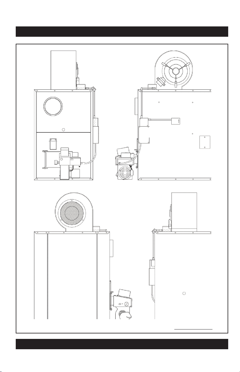
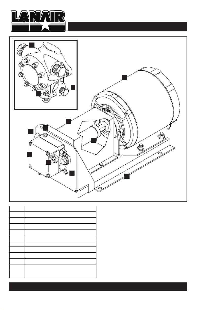
Sec.16 BurnerReferenceDiagram ....................................................page 51
Visit our website at: www.lanair.com
3
Section 15 - Warranty
QUESTIONS?... Contact Customer Service at 1-800-753-1601 -F 8:00 am- 4:15 pm CST
50
Items Not Covered Under Warranty
Conditions That Will Void Warranty
LANAIR 1O YEAR WASTE OIL HEATER
LIMITED WARRANTY
Lenan Corp., MAN FACT RER, hereby warrants that any part of manufacturer’s product shall be free from defect in
material and workmanship under normal use according to the provisions and limitations herein set forth for a period of
one (1)year provided same is returned (pre-paid) F.O.B. Janesville, Wisc. for inspection and warranty determination.
MAN FACT RER warrants the heat exchanger/combustion chamber for three (3) years from the date of purchase and
pro rata thereafter according to the following schedule: If a defect occurs during the first three years,
MAN FACT RER will repair or replace the combustion chamber/heat exchanger FREE* of charge. If a defect occurs
in years four through ten (4-10) MAN FACT RER will repair or replace your combustion chamber/heat exchanger.
Your guaranteed replacement cost will be shared by MAN FACT RER 50/50.
IMPORTANT: Combustion chamber / heat exchanger must be maintained in accordance with the installation / operat-
ing instructions. This extended warranty does not cover normal wear items such as gasket material, chamber inserts,
nuts, bolts, labor costs, etc. The warranty card must be returned within ten (10) days of purchase date in order for this
warranty to be valid. Warranty is limited to original purchaser
*MAN FACT RER’S determination regarding repair or replacement is final.
Cost of freight is owner’s responsibility.
Model Number DHI Series Heater Date Purchased:
• Any portion of the combustion chamber / heat exchanger if:
- The unit is not installed per the owners manual.
- The yearly inspection requirements are not current.
- If the heater is used for a purpose for which it is not intended.
- If the heater is not operated in accordance with the printed instructions in the
- If any alterations or unauthorized repairs are made to the unit.
• Damage incurred from overfiring, abuse, neglect, shipping, natural acts, misuse or accident.
• Labor costs for service calls for any reason including:
- Cleaning or performing required maintenance.
- Installation corrections
- Any parts installation.
• Parts that are replaced because of normal wear and tear.
• Goods purchased under this agreement shall be used exclusively by the buyer and no
other person or third party shall benefit from the express or implied warranties contained
in the agreement.
• Use of liquids such as: solvents, brake fluid, gasoline, K-1, kerosene, paint thinners, gear lube, trans-
former oil, cutting oils, anti-freeze, water or any other liquid not approved for use.
• Tampering with internal components
• Failure to inspect and clean combustion chamber/heat exchanger at the end of each heating season.
• Continuous over-firing of the unit
• Heater has not been installed or serviced in accordance to the installation / operating manual.
• Alteration or misuse of any part
• Use of parts other than those supplied by Lanair.
NOTE: Lenan Corporation may require photographs of the heater installation for warranty
determination

Section 1 - General Specifications & Hazards
QUESTIONS?... Contact Customer Service at 1-800-753-1601 -F 8:00 am- 4:15 pm CST
4
No. Description
1 Mounting Plate
2 Ignitor Transformer
3 Fuel Line Inlet
4 Fuel Pressure Gauge
5 Combustion Air Baffle
6 View Port
7 Oil Primary Safety Control
8 Waste Oil/Fuel Oil Switch
9 Quick Disconnect Receptacle
10 Air Supply Inlet
11 Combustion Blower Motor
Burner Assembly-
Performance Ratings
Voltage ......................115vac
Cycles ..........................60hz
Total Operating Amperage . . . . . . . . 5.8
Weight .........................31lbs
Oil Primary . . . . . . . . . . . . . . . . . . 0.2 amps
Pre-Heater Block . . . . . . . . . . . . .2.6 amps
Ignitor Transformer . . . . . . . . . . 0.3 amps
Installation Notes:
Visit our website at: www.lanair.com
49
10
11
9
8
7
6
5
4
3
2
1
DHI Series Burner
NOTE: This burner intended for use with DHI 300 Lanair Waste Oil-Fired
Heater Only

Section 1 - General Specifications & Hazards
Visit our website at: www.lanair.com
5
1
3
2
2
2
4
8
5
6
7
9
No. Description
1 8" Chimney xhaust
2 Mounting Holes
3 Fan Hi-Limit Switch
4 Flame View Port
5 Burner Assembly
6 lectrical Power Box
7 lectrical Panel Access
8 Clean-Out Port Access Panel
9 Blower Assembly
Section 14 - roubleshooting
QUESTIONS?... Contact Customer Service at 1-800-753-1601 -F 8:00 am- 4:15 pm CST
48
Symptom Possible Cause Corrective Action
C. Burner fires, and then 1. Contaminated fuel supply 1. Drain and clean fuel
fails on oil primary safety (water/anti freeze/gear lube) supply tank. Clean fuel
or dirty fuel filter. filter (see page 37)
2. Improper draft 2. Check draft see page 15.
Make sure chimney is
properly installed
3. Plugged heat exchanger, 3. Clean heater including
manifold, or chimney manifold and chimney
4. Wrong air pressure 4. See flame adjustment pages
29-31
5. Wrong fuel pressure or 5. See flame adjustment
pressure fluctuating pages 29-31. See fuel piping
page 17
6. Improper combustion blower 6. See flame adjustment
setting, or blower is defective pages 29-31. See fuel piping
page 17
7. Oil primary/cad cell defective. 7. Test components/adjust
Cad cell improperly adjusted. cad cell/ clean turbulator
Dirty flame turbulator.
8. Plugged nozzle or pre-heater 8. Clean nozzle and /or
assembly pre-heater assembly
D. Pre-heater assembly 1. Cartridge heaters defective 1. Test cartridge heaters
not heating or disconnected using an ohm meter.
Air heater 112 Ω±10%.
Oil heater 37 Ω±10%.
2. Snap disc defective 2. Test snap switch for
continuity if
pre-heater is cold
3. Hi-Limit snap disc defective 3. Replace snap disc assembly

Section 1 - General Specifications & Hazards
QUESTIONS?... Contact Customer Service at 1-800-753-1601 -F 8:00 am- 4:15 pm CST
6
DHI-300 FRONT
Section 14 - roubleshooting
Visit our website at: www.lanair.com
47
DIMENSIONS:
DHI-300 Height: 61” Width: 43” Depth: 47”
Weight: 370 LBS
FIRING CAPACITIES:
DHI-300 Nozzle @ 1.86 gallons/hour, No. 2 fuel oil
Symptom Possible Cause Corrective Action
A.Burner will not start 1. Main electrical power 1. Reset breaker
circuit breaker tripped
2. Service disconnect 2. Turn switch on or
switch off or fuse blown replace fuse
3. Thermostat turned down/ 3. Turn thermostat up,
improperly installed/ check wires/test
defective components/replace
4. Oil primary safety 4. Reset/test components,
tripped/defective replace if needed
5. Too much light showing 5. liminate light to cad cell
on cad cell/defective Test component
B. Burner attempts to fire, 1. Low oil in supply tank or 1. Fill tank, or drain and
but does not establish a contaminated fuel clean tank
flame
2. Plugged or worn nozzle 2. Clean or replace
3. Fuel pressure gauge 3. See section 6, Page 17
fluctuating/pumping system
4. Pre-heater switch is turned off 4. Turn switch on or test
or defective, or defective switch and cartridge heater
cartridge heater
5. Transformer/electrodes not 5. Test transformer/look
sparking for shorts & repair
Replace electrodes/
transformer
6. No air pressure/defective 6. Turn compressor on/test
regulator/defective solenoid regulator/solenoid. Replace
defective components
7. Water in air system 7. Clean air pre-heater and
drain water from system
8. Combustion blower not 8. See flame adjustment
properly adjusted or pages 29-31.
defective Replace blower
9. Improper draft 9. Check draft see page 15.
Make sure chimney is
properly installed
10. Plugged heat exchanger, 10. Clean heater including
or chimney manifold, chimney

Section 1 - General Specifications & Hazards
Visit our website at: www.lanair.com
7
Section 14 - roubleshooting
QUESTIONS?... Contact Customer Service at 1-800-753-1601 -F 8:00 am- 4:15 pm CST
46
Burner fuel pressure gauge reading hints:
Fuel gauge fluctuates (jumps):
• Suction Line Leak.
• Air in fuel, refer to Troubleshooting Chart Item B.
• Quad ring seal for the nozzle may be damaged.
• Seal in adapter block may be worn or damaged.
• Fuel pressure regulator seal leaking or dirty.
• Suction line strainer plugged or dirty.
• Dirty Pump Screen
Reading gradually decreases:
• Fuel pump output decreasing.
• Fuel viscosity decreasing.
• Orifice in nozzle is wearing.
• Dirty Pump Screen
Reading gradually increases:
• Fuel pump output increasing.
• Fuel viscosity increasing (cold fuel, and/or gear lube).
• Orifice in nozzle is becoming plugged.
Reading drops to –0- PSI when the burner is off.
• Dirt between the diaphragm and the seat in the by-pass regulator.
• Dirt between the plunger and the nozzle seat.
• Leak in the plumbing connections.
• Leak in the pre-heater assembly (damaged or missing o ring).
• Fuel pre-heater switch is off.
Steps to check the air operated fuel valve:
•Disconnect the two transformer wires from the terminal block in the burner.
• Jump the cad cell circuit (refer to page 43).
• Disconnect the fuel supply pump orange wire from the terminal block inside the
burner.
• Set the dial indicator as shown on the diaphragm piston.
• Zero the dial indicator.
• Start the burner so that the air valve opens.
NOTE: The dial indicator should read +.015 to .050, which references the diaphragm piston
travel.
FRONT
REAR
LEFT SIDE
RIGHT SIDE
8" exhaust
View port
Fan Hi-Limit
switch
Clean Out
Access Panel
Blower Moter
Assembly
lectrical Access
Panel
Power Box
Burner
Assembly

Section 1 - General Specifications & Hazards
QUESTIONS?... Contact Customer Service at 1-800-753-1601 -F 8:00 am- 4:15 pm CST
8
OPTIONAL J-PUMP
No. Description
1 Pump Platform
2 Pump Motor
3 Pump Guard
4 Pump
5 Pressure Gauge port
6 asy Flow Bleed Valve
7 1/4" NPT Inlet (1/2" J Pump)
8 1/8" NPT Outlet (1/4" J Pump)
9 Pump coupler
Pump Assembly-
Performance Ratings
Voltage ......................115vac
Cycles ..........................60hz
Weight.........................24lbs
PumpMotor ..................5amps
7
4
3
2
1
5
8
7
8
6
6
Section 14 - roubleshooting
Visit our website at: www.lanair.com
45
• Install a jumper wire between the two F-F
terminals.
• Push reset button for 2 seconds.
• Turn room thermostat up so that it calls for
heat.
• Disable the air operated fuel valve.
• To activate the oil primary momentarily dis
connect one end of the jumper wire on the
F-F terminals. The burner will attempt to fire.
IMPORTANT remove the jumper wire when
testing is complete, and replace the cad cell
wires. Do not run the heater with the cad cell
wires disconnected.
Disabling the air operated fuel valve.
Note: Most trouble shooting tests will require the air operated fuel valve to be disabled, to
do this:
• Adjust the heater air filter/regulator to -0- PSI.
Install jumper wire
Vacuum Gauge reading hints:
No reading 0-1 HG
• Pump not operating.
• Pump air locked and needs priming. Refer to section 10.
• Vacuum leak: Pump shaft seal Pump cover gasket
Suction strainer gaskets Low fuel level in tank
Pipe connections suction side Strainer in pump cover
Low to normal reading, 1-6 inches HG.
•Pump operating properly. • Fuel being used has a low viscosity.
• Fuel oil is being used. • Fuel is at room temperature (warm).
• High level of gasoline in the fuel (use approved fuels only).
High reading, 7 inches of HG, or more.
• Fuel being used has to high of a viscosity. • Suction line strainer dirty or plugged.
• Fuel is too cold. • Check valve installed wrong or stuck.
• Fuel contains gear lubes (use approved fuels only).
Reading fluctuates (jumps).
• Vacuum leaks in the suction side of the piping to the pump.
• Low fuel level in the tank.
9

Section 1 - General Specifications & Hazards
Visit our website at: www.lanair.com
9
• The Lanair Heater provides the owner with a dependable, versatile and simple means of
burning No. 1 and No. 2 fuel oils, 5W through 50W used crankcase oils, and used auto-
matic transmission fluids. Maintained correctly, the heater will give you years of service.
Please carefully read this owner’s manual. If in any case you have a problem with your
heater, or its installation, you should contact the Lanair Customer Service Department at
1-800-753-1601.
• Do not attempt to start the burner when excess oil, oil vapor, or fumes have accumulat-
ed! Never press the red button on the oil primary control more than twice! This could
cause excess vapor, or fuel to ignite causing damage to the heater and/or chimney.
• Do not store or use gasoline, or any other flammable liquid and/or vapors near this
heater.
• This heater is not designed for use in hazardous atmospheres such as: Paint Shops, Feed
Mills, installations where explosive or flammable conditions are present or could occur.
DIMENSIONS:
Height: 61” Width: 43” Depth: 47”
Weight: 370 LBS
FIRING CAPACITIES:
DHI-300 Nozzle @ 1.86 gallons/hour, No. 2 fuel oil
MINIMUM CLEARANCE TO COMBUSTIBLES:
Top . . . . . . . . . . . . . . . . . . . . . . . . 6” Chimney Connector . . . . .18”
Sides ......................18” Rear..................... 6”
Front ......................24” Bottom .................18”
THIS HEATER IS DESIGNED TO BURN THE FOLLOWING APPROVED FUELS:
Used 5W through 50W Crankcase Oils
Used Automatic Transmission Fluid
No. 1 and No. 2 Fuel Oils
WARNING! Lanair heaters rely on natural draft. Down drafts (positive pressures)
in the heaters chimney will occur in buildings where negative pressures are created
by exhaust fans, (car exhaust, paint booths, etc). Do not try to use a power vent to
overcome a down draft (positive pressure). An adequate make-up air system is
required when exhaust fans are used (consult your heating contractor).
!
Section 14 - roubleshooting
QUESTIONS?... Contact Customer Service at 1-800-753-1601 -F 8:00 am- 4:15 pm CST
44
Initial Diagnosis:
When an operating problem occurs, a determination must be made whether or not the fuel
pump is pumping a sufficient amount of oil that contains no air or water.
Take these steps:
• Adjust the burner air regulator to -0- PSI.
• Turn pre-heater rocker switch off (red light off).
• Shut off oil supply line valve to the burner.
• Remove the fuel supply line from the supply tank.
• Attach a flexible piece of tubing at least 3 feet long to the outlet on the return side of
the oil by-pass regulator.
• Insert the tubing into the bottom of a large jar.
• Jump the cad cell circuit and start the fuel pump (see below).
• Attempt to fill the jar above the open end of the tubing.
• If the pump will not pump fuel, attempt to prime the pump (Section 10). If the pump
won’t prime refer to Flow Chart Item B.
If no air or water is present the flow must be determined.
• Pump fuel for 1 minute into a graduated container, if the flow rate is less the 250
MILS/Minute (8-1/2 Ounces), refer to Section 13 Troubleshooting Chart Item B.
If the flow rate is more than 250 MILS/minute (8-1/2 Ounces), refer to Troubleshooting
Chart Item C.
After repairs are made, remove the cad cell jumper wire, and reconnect the cad cell wires to
the oil primary.
By-passing the oil primary safety circuit:
Some trouble-shooting test may require the cad
cell safety circuit in the oil primary control to be
bypassed, to do this:
• Remove the 2 yellow wires from the F-F
terminals on the oil primary control.
Remove two yellow wires
FIRE HAZARD WARNING: DO NOT OPERATE YOUR HEATER IF THE OIL
PRIMARY SAFETY CIRCUIT IS NOT WOR ING!
!

Section 2 - Heater Installation
QUESTIONS?... Contact Customer Service at 1-800-753-1601 -F 8:00 am- 4:15 pm CST
10
TYPICAL INSTALLATION:
HEATER/CHI NEY PACKAGE
Through the wall installation
Figure 1
Section 13 - Service / Maintenance
Visit our website at: www.lanair.com
43
Fuel By-Pass Regulator
Diaphragm Replacement
1. Disconnect power to the heater.
2. Remove the locking nut and adjusting
screw from the by-pass regulator
assembly.
3. Disassemble the by-pass regulator and
discard the small plug, spring, large
plug, washer and diaphragm.
4. Thoroughly clean and dry remaining
parts.
5. Re-assemble using new small plug,
spring large plug, washer and
diaphragm (Kit P/N 9874).
NOTE: Pay close attention to the posi-
tions of the large and small plugs.
adjusting screw
locking nut
cap
small plug
spring
large plug
washer
diaphragm
body
Fuel By-Pass Regulator Assembly
1. Chimney Cap
2. Chimney Pipe
3. Clean-out Tee
4. Wall Thimble
5. Barometric Damper
6. Black Pipe
7. Burner
8. Blower Assembly
9. Secondary Air Regulator
10. Primary Air Regulator
11. Duct Connectors
12. Fuel Line
13. By-pass Regulator
14. Oil Strainer
15. Pump Assembly
16. Oil Storage Tank
17. Thermostat
18. Power Supply

Section 2 - Heater Installation
Visit our website at: www.lanair.com
11
General Requirements
1. Do not install the heater on a combustible surface of any kind. For minimum clearance to
combustible material (see Page 9)
2. Install the heater in a location to utilize total heat throw.
3. Install the heater in a location to permit a correct outdoor chimney exit to eliminate
down drafts, and provide easy chimney installation and maintenance. Class A chimney
MUST be used when passing through any wall or ceiling. See Section 3 Chimney
Installation
4. Install the heater in a location to permit the fuel supply to be as close as possible.
5. Do not install the heater more than 10 feet above the top of the fuel supply tank.
6. Before suspending the heater check the supporting structure and reinforce if necessary
to support the weight of the heater/system.
7. Use 3/8” steel threaded rod to suspend the heater from a capable load carrying ceiling
structure when not using the Lanair Waste Oil Storage Tank.
8. The heater must be suspended level for proper operation. A heater that is not level could
cause a hazardous situation in which personal injury or property damage may result.
Section 13 - Service / Maintenance
QUESTIONS?... Contact Customer Service at 1-800-753-1601 -F 8:00 am- 4:15 pm CST
42
5. Use an industrial type canister vacuum cleaner with a high efficiency filter, or ash rake to
pull the ash to the front of the heat exchanger tubes for removal. Failure to clean heat
exchanger tubes annually will impair draft. Vacuum or shovel the ash from the combus-
tion chamber. Inspect the combustion chamber and target brick. Use care when cleaning
the combustion chamber area so the target brick is not disturbed. Insufficient or irregu-
lar cleaning intervals will cause inefficiency, random shutdowns, and extreme damage to
the combustion chamber.
6. Before replacing the gun/chamber access doors, replace the white gasket seals on the
doors (contact the Lanair Service Department). When replacing the gaskets apply a light
film of gasket adhesive to adhere the new gasket to the door. Lube the threads of the
screws with a high temperature lubricant. If any screws are stripped or broken, replace.
7. Re-install the galvanized cover panels.
8. Re-install the inspection port cover. Replace burner.
9. Remove the manifold clean out port cover on the front of the unit (marked 5 on illustra-
tion on page 41). Using an industrial type canister vacuum cleaner with a high efficiency
filter, remove all ash accumulation.
10. Install a new gasket and re-attach the clean out port cover using the screws removed
previously. Check your draft reading to make sure your barometric damper is properly
set (See Section 5).
11. Reconnect all power at the main breaker box, wait ten minutes before turning the ther-
mostat up. Your heater is now ready for normal operation.
NOTE: When changing the target brick, call the Lanair Service Department for assistance.
CAUTION: THE CLEAN OUT PANEL MUST HAVE AN AIR TIGHT SEAL TO
PREVENT EXTREME DAMAGE TO THE COMBUSTION CHAMBER
!
WARNING: DO NOT OPERATE YOUR FURNACE WITH CLEAN OUT PANELS
OR PORTS REMOVED
!
CAUTION: TO AVOID SCREW BREA AGE, DO NOT OVER-TIGHTEN
!
CAUTION: DUCT WOR RUNS MUST BE DESIGNED AND INSTALLED BY A
LISCENSED HEATING CONTRACTOR
!

Section 3 - Chimney/Vent System
QUESTIONS?... Contact Customer Service at 1-800-753-1601 -F 8:00 am- 4:15 pm CST
12
Figure 2 - Typical Chimney Installation
NOTE: Class "A" compo-
nents require a 2" clear-
ance from combustible
materials. All other
chimney components
require a minimum 18"
clearance from com-
bustible materials
FAILURE TO PROVIDE PROPER VENTING OF THE HEATER EXHAUST
GASES COULD RESULT IN DEATH, SERIOUS INJURY, AND/OR PROPERTY
DAMAGE. FOLLOW CHIMNEY MANUFACTURERS INSTRUCTIONS.
!
General Requirements
1. Safe operation of any gravity vented heating appliance requires a proper air make-up
system to prevent the heater exhaust gases from being drawn into the building. These
gases could cause death, serious injury, and/or property damage. xhaust fans, paint
booths may cause draft problems.
2. Never vent this heater into another heating appliances chimney. Never vent into ‘Class B”
chimney. Gas heaters use “Class B” chimney, it is rated for a much lower temperature than
is required for your waste oil furnace. This heater must have its own separate“Class A”
chimney.
3. Inspect and maintain the chimney on an annual basis.
Section 13 - Service / Maintenance
Visit our website at: www.lanair.com
41
Cleaning Combustion Chamber/ Heat Exchanger
1. Turn thermostat to the lowest setting; the heater must be completely cool to the touch
before attempting to clean the heater (place the fan/limit on the manual position to
start the fan and shorten the cooling time if the unit is hot). Turn off all power to the
heater (120 VAC) at the main disconnect. Place the fan/limit switch lever back into the
auto position so the fan is off upon restarting.
2. Remove the chimney connector from the heater.
3. Remove the burner and flame view port from the heater. Remove the galvanized panels
covering the gun/chamber doors.
4. Remove the gun/chamber doors from the heater by removing all of the screws.
NOTE: ALWAYS WEAR EYE, FACE AND BREATHING PROTECTION AND PROTECTIVE
CLOTHING WHEN INSPECTING OR CLEANING CHAMBER OR HEAT EXCHANGER.
!
NOTE: SPRAY ALL OF THE SCREWS WITH PENETRATING OIL TO PREVENT BREA -
AGE. BEFORE REMOVING LET SET FOR FIVE MINUTES TO ALLOW THE OIL
TO PENETRATE. REPLACE STRIPPED OR BRO EN SCREWS.
!
WARNING: DISCONNECT ALL ELECTRICAL POWER TO HEATER BEFORE SERVICING
!

Section 3 - Chimney/Vent System
Visit our website at: www.lanair.com
13
General Requirements (cont.)
4. Install a U.L. listed barometric damper in the chim-
ney. Do not reduce or enlarge the vent pipe.
5. ach 90° elbow equals a 10’ run of chimney. The
maximum run for the chimney connector is 30’ (See
illustrations on pp. 12 & 14).
6. To prevent the drawing of exhaust gases into the
building, keep the barometric draft control at least
24” from the heater, exhaust fan etc..
7. Position the draft control as shown. Barometric
Damper gate pins must be horizontal (Level or
parallel to the floor) for proper operation.
8. Secure all connections in the chimney connector with 3 screws per joint.
9. The chimney connector clearance to any combustible material is 18”. The “Class A”
chimney clearance to any combustible is 2”. Follow the chimney manufacturer’s instruc-
tions.
10. Do not install heat re-claimers, manual draft controls, or any other type of restrictive
control in the chimney.
11. Install clean out tee with a cap, at the transition of the chimney. FOLLOW CHIMNEY
MANUFACTURERS INSTRUCTIONS.
12. Use “Class A” insulated chimney pipe to vent exhaust gases through wall, ceilings, attics,
roofs, combustibles, etc. Class A chimney must be used for the entire run once passing
through a wall of ceiling.
13. Vent chimney at least 3 feet above the roof and at least 3 feet higher than any portion
of the building, roof, or obstruction within 10 feet of the chimney.
14. The chimney cap should be at least 3’ above the chimney exit through the roof.
15. Do not use a rotating chimney cap. Use a non-restrictive “Class A” cap made for the type
“Class A” chimney you are using. Follow chimney manufacturer’s instruction.
16. The chimney must be capable of producing a negative -.02 W.C. draft when cold and -
.06 W.C. draft when hot. Refer to Section 5 Draft Instructions. Refer to Section 3.10 for
typical Chimney Installation.
HORIZONTAL
V RTICAL
NOTE: Barometric Damper may
be mounted horizontally or
vertically. Angle gate pins
must be horizontal (level or
parallel to floor) for proper
operation.
Barometric Damper Position
Section 13 - Service / Maintenance
QUESTIONS?... Contact Customer Service at 1-800-753-1601 -F 8:00 am- 4:15 pm CST
40
Air Pre-Heater Diaphragm
Replacement
1. Remove the four hex cap screws
from the diaphragm assembly and
discard.
2. Disassemble and discard diaphragm,
spring and o-ring .
3. Thoroughly clean remaining parts.
4. Re-assemble using new diaphragm,
o-ring, spring and hex cap screws.
Air Pre-Heater Nozzle Cleaning /
Replacement
1. Periodic cleaning of the nozzle
assembly may be required.
2. Carefully remove nozzle from the air
pre-heater block.
3. Disassemble the nozzle as shown
and clean thoroughly. Re-assemble
nozzle.
4. Carefully remove the quad ring from
the block and inspect. Replace if nec-
essary.
5. Insert clean/new quad ring into the
air pre-heater block. NOTE: The quad
ring must be properly seated.
Failure to properly seat the quad
ring may result in leakage and
improper burner operation. DO NOT
INSTALL QUAD RING ON THE NOZ-
ZLE.
6. Lubricate pin/seat and re-install noz-
zle. Tighten securely.
!
Failure to properly seat the quad
ring may result in leakage and
improper burner operation. DO
NOT INSTALL QUAD RING ON
THE NOZZLE.
Air Pre-Heater Diaphragm Assembly
Air Pre-Heater Nozzle Assembly
Proper Quad Ring Position
diaphragm
fuel orifice
body
pin/seat
nozzle assembly
quad ring
piston
spring
hex cap
screws
o-ring
!
DO NOT INSTALL CHIMNEY IN FRONT OF
THE HEATER (in air stream of fan)

Section 3 - Chimney/Vent System
QUESTIONS?... Contact Customer Service at 1-800-753-1601 -F 8:00 am- 4:15 pm CST
14
17. If you are unable to attain the proper draft, check for exhaust fans in the building.To test
if there is a problem, open an overhead door and see if you now have the proper draft.
You may have to add one or more sections of “Class A” chimney to the roof to get the
proper draft.
18. The heater and chimney must be installed in accordance with all state and local
codes.The heater must be installed in accordance with the specifications listed in
this manual. The chimney must be installed per the chimney manufacturer’s
instruction. Use “Class A” chimney only.
Section 13 - Service / Maintenance
Visit our website at: www.lanair.com
39
Ignitor Replacement /
Adjustment
1. Disconnect power to the heater.
2. Remove the pre-heater assembly
from the burner housing.
Disassemble and clean all parts
as instructed on pages
34-37.
3. Using a 1/4" wrench, carefully
remove the one-piece ignitor
from the air pre-heater.
4. Install a new one piece ignitor
(P/N 3730) to the top of the air
pre-heater. NOTE: The tips of the
ignitor should be 3/8" above the
center of the nozzle assembly
and should extend approximate-
ly 1/8" beyond the end of the
nozzle. The tips of the one piece
ignitor should be 1/8" apart at
bend. Adjust as required and
tighten nut on the top of the
ignitor (see illustrations for clarifi-
cation of placement).
5. Re-assemble pre-heater assembly
(see pages 34-37) carefully re-
install the pre-heater assembly
into burner housing. The turbula-
tor should be approximately 1/4”
from the end of the burner tube.
Adjust as required and secure the
pre-heater assembly to the burn-
er housing by tightening the
adjustment screw on the side of
the burner housing (see illustra-
tion).
electrodes should extend approximately
1/8” beyond nozzle tip
3/8”
1/16”
Side View
Top View
1/8”

Section 4 - Draft
Visit our website at: www.lanair.com
15
Figure 3
The Lanair heater should have a (negative) -.02 draft reading when cold, and a (negative) -.06
when hot. Check the heater when it is running after 45 minutes. If the reading is not what it
should be, adjust the barometric damper according to the instructions provided with the
damper. The draft reading should be taken with a manometer. Consult your heating contrac-
tor, or a manometer can be purchased from the Lanair Customer Service Department .
Section 5 - Fuel Supply ank Installation
Section 13 - Service / Maintenance
QUESTIONS?... Contact Customer Service at 1-800-753-1601 -F 8:00 am- 4:15 pm CST
38
bolt
washer
o-ring
inlet 1” NPT
outlet 1” NPT
strainer
strainer
hex cap screws
gasket
gasket
o-ring
spring
bowl
water drain
Cleaning Suction Line Strainer
The suction line strainer should be cleaned
every 30 days of operation. The element is
a washable metal element. If your waste oil
is extremely dirty, this strainer may need to
be cleaned more frequently.Your vacuum
gauge will help you determine when the
filter needs cleaning. The vacuum gauge
reading should not exceed 5" HG of
vacuum. If it does, the strainer needs
cleaning.
1. Disconnect power to the heater.
2. While holding the lower housing,
unscrew the center bolt on the top of
the suction line strainer.
3. Rinse the filter and lower housing in
solvent.
4. Air dry the strainer and lower housing.
5. Re-assemble the strainer, ensuring the
rubber gaskets, spring and o-rings are
in place.
6. Fill the lower housing with waste oil or
fuel oil.
7. Position the lower housing to the top
making sure the o-ring is properly seat-
ed. Secure the top and bottom togeth-
er using the bolt, washer and gasket
removed earlier.
8. Prime the fuel pump (see page 25).
Cleaning/Replacing Fuel Pump
Strainer
1. Disconnect power to the heater.
2. Remove four hex head screws from
pump cover. Carefully remove cover,
strainer and gasket.
3. Clean housing, strainer and pump sur-
face. Check for excess wear.
4. Install a new gasket (P/N 9817).
5. Install strainer and pump housing.
6. Prime the fuel pump (see page 25). NOTE: For illustrative purpose only. Individual tank installations will vary.

Section 5 - Fuel Supply ank Installation
QUESTIONS?... Contact Customer Service at 1-800-753-1601 -F 8:00 am- 4:15 pm CST
16
General Requirements
1. The fuel supply tank and supply lines must be installed in accordance with the National
Fire Protection Association requirements, as well as State and Local ordinances.
2. Regulations require oil storage tanks located inside not too exceed 275 gallons individu-
ally, and are not to exceed a total capacity of 550 gallons in one building. Check State
and Local codes.
3. Locate the fuel supply tank inside the building as close to the heater as possible. It
should be no further than 25 feet from the heater to avoid oil flow problems.
4. The fuel supply tank must be mounted below the level of the burner and the by-pass
regulator. Mounting the fuel supply tank above the burner will create head pressure and
over-fire the burner voiding the warranty.
5. Pitch the fuel supply 2º with the drain valve at the lowest end to drain off water and
sludge. Sludge may have to manually be removed.
6. Some ordinances may require the fuel supply tank to be vented to outside, and above
the roofline. Check State and Local codes. Keep the vent clear.
7. Install the fuel tank fill pipe at the end of the tank and above the drain.
8. Label the fuel tank for the recommended fuels.
9. Strain all fuel with a 50 X 50 mesh strainer before putting fuel into the tank.
10. When filling the fuel tank with a motorized pump, never leave unattended to prevent
over filling and/or spillage.
11. Keep cap on the fuel tank when not filling.
If using a Lanair supply tank follow instructions included with the tank.
!
For optimum performance, the waste oil pump manufacturer recom-
mends that multi-weight oils such as 5W-30W be maintained at 32˚ F
minimum and straight weight oils such as 40W and 50W be maintained
at 50˚ F minimum.
!
Section 13 - Service / Maintenance
Visit our website at: www.lanair.com
37
Maintenance - OIl Pre-Heater (cont.)
3. Clean Oil Pre-Heater Block
• Clean oil pre-heater block using a parts washer and brush. NOTE: Make sure all
passages are clean.
• Blow dry the oil pre-heater block. inspect ALL passages making sure they are clear and
clean.
4. Reassemble Oil Pre-Heater
• Replace four 13/16" OD o-rings (4) with new.
• Replace cartridge heater. NOTE: Do not over-tighten.
• Re-attach face plate (2) using six new hex cap screws (3) provided with tune-up kit
(P/N 7240).
• Apply loc-tite to three block plugs (12) and replace.
• Replace hex cap screw (9) inside oil pre-heater block (5).
• Replace o-ring (10) with new.
5. Attach Air Pre-Heater Assembly
• Align the holes of the ignitor assembly and air pre-heater with those of the oil pre-
heater (see page 34).
• Attach air pre-heater assembly to the oil pre-heater block (5) using two hex cap screws.
Tighten securely.
6. Re-install Pre-Heater Assembly
• Place the air/oil pre-heater assembly into the burner body.
• Align the holes of the pre-heater assembly with those in the burner body.
• Secure the assembly to the body by re-installing the button hex screw (14) and washer
(11). NOTE:Do not tighten this screw at this time.
• Replace the o-rings (7) on the PSI gauge and the oil line fittings (6) with new.
NOTE:Do not tighten these fittings at this time.
• Adjust the pre-heater assembly for proper setting. The end of the turbulator should b
recessed approximately 1/4” into the burner tube (see page 38 for turbulator
adjustment).
• Once adjusted tighten button hex screw (14) and fittings (6)securely.
7. Re-connect Electrical
• Re-connect all wires previously disconnected in the electrical junction box (refer to
wiring diagram, page 21 and the burner reference diagram, page 51).
8. Reconnect PSI Gauge, Fuel Line and Air Line
• Reconnect the PSI gauge (8) to the fitting (6) and tighten securely.
• Reconnect the fuel line to the fitting (6) and tighten securely.
• Reconnect the air line by connecting the one end of the air line to the air solenoid and
the other end to the air fitting (see page 34).
9. Test Operation
• Follow start-up procedure, page 26.

Section 6 - Fuel Supply Pump/Piping
Visit our website at: www.lanair.com
17
General Requirements
1. Mount the fuel supply pump in a horizontal position (shaft horizontal) near the fuel sup-
ply tank.
2. The oil pump has a maximum suction lift of 14 feet. Suction lift is the length of pipe run
from the bottom of the pick up strainer to the fuel supply pump.
3. The fuel pump/motor are intended for indoor use only.
4. The fuel pump contains an internal strainer that periodically needs to be cleaned.This
internal strainer is mounted behind the pump cover. Before removing the pump cover
make sure you have a new gasket on hand. Contact the Lenan Customer Service
Department for the proper gasket for your model of pump, at 800-753-1601.
5. Install the suction supply line from the inlet side of the fuel pump into the fuel tank
opposite the drain.
6. Install a 1/2” inside diameter (.493) steel pipe, or 1/2” outside diameter copper through-
out the suction supply line and pick up tube.The use of smaller line, or rubber, plastic or
hydraulic line is unsafe and will void your warranty.
7. Use thread sealing compound on all pipe thread connections. Do Not Use Teflon Tape.
8. Install the suction line strainer in the suction line. Make sure the suction line strainer is 6”
off the bottom of the tank.The suction line strainer may be mounted horizontally or ver-
tically. Consider accessibility.
9. Install a 1/2” NPT pipe union between the suction line strainer and the pick up tube to
allow for service on the pick up tube.
10. Install the check valve (arrow facing towards the pump) on the bottom of the pick up
tube.
11. Install a vacuum gauge in the suction line.This gauge will indicate when service is need-
ed on the strainer, pump or connections.
12. Install a 1/2” inside diameter (.493) steel pipe, or 1/2” outside diameter copper from the
fuel by-pass regulator (port marked “O”) to the fuel supply pump. Do not allow this line
to protrude into the tank more that 1”The use of smaller line, or rubber, plastic or
hydraulic line is unsafe and will void your warranty.
13. Do not allow the fuel level in the tank to cover the return line.
Section 13 - Service / Maintenance
QUESTIONS?... Contact Customer Service at 1-800-753-1601 -F 8:00 am- 4:15 pm CST
36
Oil Pre-Heater Tune -Up
Kit (PN# 9869) Required.
Ref. Part
No. No. Qty. Description
1 8992 1 cartridge heater
2 9813 1 pre-heater face plate
3 9869 6 hex cap screw *
4 9869 4 o-ring 13/16" OD *
5 2901 1 oil block
6 9029 2 fitting
7 9869 2 o-ring 5/16" OD *
8 8498 1 oil gauge
9 7242 1 hex cap screw
10 9869 1 o-ring 1/2" OD *
11 7418 1 washer
12 7109 3 plug
13 9366 1 snap disc assembly
14 7242 1 button hex screw
* contained in tune up kit 9869
Maintenance - OIl Pre-Heater
1. Separate Air Pre-Heater from Oil
Pre-Heater
• Remove o-ring and discard(10).
2. Disassemble Oil Pre-Heater
• Remove o-ring and discard(10).
• Remove six hex cap screws (3)
from face plate (2) and discard.
• Remove oil cartridge heater (1).
• Remove four 13/16"OD o-rings
and discard(4).
• Remove three plugs (12) from oil
block (5)
• Remove hex cap screw (9) from
inside oil pre-heater block and
clean. NOTE: Do not discard (5).

Section 6 - Fuel Supply Pump/Piping
QUESTIONS?... Contact Customer Service at 1-800-753-1601 -F 8:00 am- 4:15 pm CST
18
14. Install the fuel supply line from the fuel by-pass regulator (port B) to the inlet port on the
left side of the burner using 1/2” inside diameter (.493) steel pipe, or 1/2” outside diame-
ter copper tubing.The maximum distance of this line is 25 feet.The fuel supply line must
be run below the burner at all times. If the fuel supply line runs above the burner it will
create head pressure. This head pressure will over-fire the burner voiding the warranty.
15. Install a union in the supply line close to the burner for service.
16. Install a shut-off valve in the fuel supply line at the fuel by-pass regulator for service.
17. Use 37º flare fittings on all copper tubing connections. Do not use compression fit-
tings.
18. Keep the fuel supply lines 1” off any outside walls.
19. The fuel supply line must gradually rise to the burner. It should not be higher than the
burner.
20. Clean all lines, fittings, and parts internally before assembly. A small burr or piece of
rust could plug the nozzle. See Section 2 for an illustration of a typical pump and piping
installation.
B. Port to the oil inlet on the burner assembly.
Install 1/2” O.D. min. copper tubing, or 1/2”
schedule 40 pipe. Failure to install this line
properly will result in damage to your
heater, and will void your warranty.
T. Port to the oil supply tank for the overflow
return line. Install 1/2” O.D. min. copper tubing.
or 1/2” schedule 40 pipe. This line MUST run
straight into the tank, and should not be sub-
merged in oil. No elbows should be used.
Failure to install this line properly will result
in damage to your heater, and will void your
warranty.
P. Port from the outlet side of your fuel supply
pump. Install 1/2” O.D. min. copper tubing, or
1/2 schedule 40 pipe. Failure to install this
line properly will result in damage to your
heater, and will void your warranty.
Bottom View of the Aluminum Oil
By-Pass Regulator
Figure 4
Section 13 - Service / Maintenance
Visit our website at: www.lanair.com
35
Maintenance - Air Pre-Heater (cont.)
6. Clean all parts using a parts washer
• All passages must be thoroughly cleaned with a brush.
7. Replace Nozzle Assembly and Quad Ring
• After cleaning air pre-heater assembly, blow dry.
• Install new quad ring (4). Before inserting quad ring in air pre-heater block, a light coat
of oil should be applied. NOTE:Make sure quad ring is properly seated in block before
proceeding (see page 40 for clarification).
• Apply a light coat of oil to the shaft of the new nozzle assembly (3). Carefully insert new
nozzle assembly (3) through the quad ring and into the block and tighten securely.
• Check alignment of ignitors and adjust if necessary (see page 39).
8. Replace O-rings and Plunger
• Insert a new 1/4" o-ring (10) and a new 11/16" o-ring (11) into the air pre-heater
block (5).
• Insert new Viton insert (14) into the end of the plunger (15) and place new spring (13)
on the end of the plunger. Insert plunger into air pre-heater block spring end first.
9. Replace Cartridge Heater
• Apply pipe dope to cartridge heater threads. Insert cartridge heater into air pre-heater
block and tighten.
10. Replace Adapter Assembly
• Align the holes of the adapter assembly (16) with those on the air pre-heater block (5).
NOTE: Make sure the small end of the adapter pin is facing toward the air pre-heater
block.
• Attach the Adapter assembly (16) to the block using two hex cap screws (17).Tighten
screws.
11. Replace Diaphragm
• Replace diaphragm, o-ring and spring (see page 40) Hand tighten diaphragm assembly
to air pre-heater block. NOTE: Do not over tighten.
12. Replace Ignitor Assembly (see page 40)
13. Service Oil Pre-Heater (see pages 36-37 for Annual Maintenance Instructions)

Section 7 - Air Supply Installation
Visit our website at: www.lanair.com
19
General Requirements
1. Install an air pressure supply line connection to the air filter/regulator on the rear of the
heater.
2. The air supply source must be capable of producing 2.0 CFM @ 60 PSI.
3. Install a shut off valve in the air supply line for service.
4. Install a primary air filter/regulator with a gauge (capable of reading line pressure) in the
air supply line prior to the air filter/regulator mounted on the furnace.The primary air fil-
ter/regulator is not supplied with the furnace.
5. If the primary air regulator does not have a filter with a bowl, a condensate drain leg
must be installed in the air supply line.
6. Install a quick disconnect at the air filter/regulator on the furnace for service.
7. For the ease of installation install a flexible air line (.250 I.D. minimum) from the quick
disconnect to the primary air regulator.
8. The air supply line must be pitched uphill from the primary regulator to the furnace to
prevent condensation from entering your burner.
9. Open all air shut off valves, and set the primary air regulator at 30 PSI.
10. Set the air filter/regulator on the front of the furnace to 15 LBS. See illustration below
(Fig. 5) for a typical air pressure supply installation.
Figure 5
Section 13 - Service / Maintenance
QUESTIONS?... Contact Customer Service at 1-800-753-1601 -F 8:00 am- 4:15 pm CST
34
Maintenance - Air Pre-Heater
1. Remove Pre-Heater Assembly
• Disconnect the air line from the
brass fitting on the air pre-heater
and then from
the air solenoid and remove.
• Disconnect wiring from the oil pre-
heater cartridge, air pre-heater
cartridge and snap disc assembly in
the wiring junction box.
• Disconnect fuel line and fitting (6)
from the oil block (5).
• Disconnect fuel pressure gauge (8)
and fitting from the oil block (5).
• Remove button hex screw (14) and
washer (11).
• Lift pre-heater assembly and care
fully pull straight back. Remove
entire assembly from the burner.
• Remove ignitor assembly (6).
2. Remove Diaphragm Assembly
from Air Pre-Heater
• Carefully place pre-heater assembly
in a vice. NOTE: Do not damage
pre-heater.
• Unscrew diaphragm assembly (19)
from air pre-heater and set aside.
Remove o-ring and discard.
3. Remove Adapter Assembly
• Remove hex cap screws (17) and set adapter
assembly aside.
4. Remove Plunger , Spring and Cartridge Heater
• Remove spring (13) from plunger (15) and discard.
• Using a hook or screwdriver, carefully remove Viton
insert (14) and discard.
• Remove and discard 1/4" o-ring (10) and 11/16" o-
ring (11).
• Loosen and remove cartridge heater and set aside.
5. Remove Nozzle Assembly and Quad Ring
• Remove nozzle assembly (3) using a 9/16" wrench.
• If quad ring (4) does not come out with nozzle, care
fully remove it and discard.
Ref. Part
No. No. Qty. Description
1 9853 1 turbulator
2 7004 1 set screw
3 9757 1 nozzle Heater 260/300
4 9870 1 quad ring (K)
5 9814 1 air pre-heater block
6 3730 1 ignitor assembly
7 9870 2 hex cap screw *
8 7418 2 flat washer
9 3726 1 connector
10 9870 1 1/4" o-ring *
11 9870 1 11/16" o-ring *
12 9856 1 air cartridge heater
13 9870 1 spring *
14 9870 1 Viton insert *
15 9835 1 plunger
16 9838 1 Adapter block assembly
17 9870 2 hex head cap screw *
18 9871 1 1/2" o-ring (K)
19 9871 1 diaphragm assembly **
20 9871 2 hex head cap screw **
22 oil pre-heater block
* contained in tune up kit 9870
** contained in tune-up kit 9871
Remo e wires from the block by
inserting a flat tip screwdri er into the
top slot. Push tip all the way down
and carefully push forward. Remo e
wire.

Section 8 - Electrical Connections
QUESTIONS?... Contact Customer Service at 1-800-753-1601 -F 8:00 am- 4:15 pm CST
20
CAUTION: HAZARD OF ELECTRICAL SHOC !
!
Main Electrical Installation
1. All wiring must comply with the National lectrical Code. State and Local Ordinances,
and be wired by a qualified electrician.
2. lectrical service MUST be connected to two separate 20 AMP, 115 VAC, 60 HZ single
phase circuit.
3. lectrical service connections are made in the electrical junction box on the side of the
heater.
4. The heater must have a safety equipment ground from the main electrical service,
stranded 12 GA minimum.
5. The electrical conductors for electrical service to the heater MUST be stranded 12 GA
minimum.
6. Install a manual service disconnect near the heater, and label its function.
7. The supply voltage must be maintained at a minimum 110 VAC.
8. The electrical conductors from the main electri-
cal service must be within approved conduit.
9. Keep all electrical conductors and conduit away
from the chimney connector as well as any
other hot surfaces. Refer to Figure 7, Wiring
Diagram for color code, etc. Keep the power off
until the heater is ready to be started. Refer to
Section 12 Start Up Procedure.
Remove wires from the block by insert-
ing a small flat tip screwdriver into the
top slot. Push tip all the way down and
carefully push forward. Remove wire.
Figure 6
Section 13 - Service / Maintenance
Visit our website at: www.lanair.com
33
Air Pre-Heater Tune -Up
Kits (PN# 9870 & 9871) Required.
Table of contents
Other Lanair Heater manuals
Popular Heater manuals by other brands

Herschel
Herschel CALIFORNIA 2000 Installation & operating instructions

Pinnacle Climate Technologies
Pinnacle Climate Technologies Remington REM-47-TTC-O User's manual & operating instructions

VIGO
VIGO EPK4550E05 user manual

Dyna-Glo
Dyna-Glo RA125DGD Operating instructions and parts manual

HOMCOM
HOMCOM 820-244 operation instruction

Herschel
Herschel Krystal-600-B Installation & operating instructions

KING
KING SL Series installation instructions

Warmup
Warmup HTR-4ROPO installation manual

HEATSTRIP
HEATSTRIP Classic THH1500AUL Operation, installation, and maintenance manual

Broan
Broan 9815WH SERIES installation instructions

Exquisit
Exquisit HL 32025 we instruction manual

Click
Click CTH-2300R instruction manual