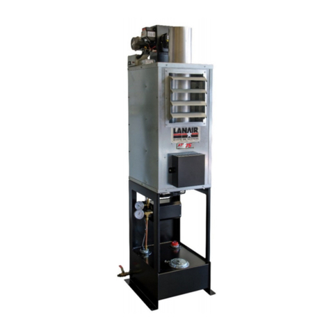
Lanair XT Series User manual

Lanair ProductsLLC
4109 Capital Circle
Janesville, Wisconsin 53546
1-888-370-6531
www.lanair.com
XT SERIES:
150, 200, 250, 300
WASTE OIL HEATER
Installation and
Operating Instructions


Visit our website at: www.lanair.com
i
SAFETY, CODES, AND REGULATIONS
Thank you for the purchase of a Lanair used oil furnace. Lanair furnaces are designed and
tested for safe, reliable long term operation. However, proper installation, fuel quality con-
trol, and regular maintenance are required. Please read and understand this manual com-
pletely before attempting to install, operate, or service the furnace. Keep this instruction
manual and maintain it in legible condition. If you have any questions, please go to www.
lanair.com or call 1-888-370-6531 for Lanair Technical Service.
CONVENTIONS USED IN THIS MANUAL
For your safety, this manual uses the following denitions and signal words to identify
hazards:
Danger: Indicates an imminently hazardous situation which, if not avoided,
will result in death or serious injury. This signal word is limited to the most
extreme situations.
Warning: Indicates a potentially hazardous situation which, if not avoided,
could result in death or serious injury.
Caution: Indicates a potentially hazardous situation which, if not avoided,
may result in minor or moderate injury. It may also be used to alert against
unsafe practices.
Caution (without alert symbol): Indicates an unsafe practice which, if not
avoided, may result in product or property damage. Also used for general
alerts.
PRODUCT SAFETY LABELS AND THEIR MEANING:
BEFORE YOU BEGIN INSTALLATION...
NOT ALL LABELS USED ON ALL PRODUCTS

QUESTIONS?... Contact Customer Service at 1-888-370-6531 M-F 8:00 am- 4:15 pm CST
ii
BEFORE YOU BEGIN INSTALLATION...
•This heater is for commercial and industrial use only. This unit is not intended for residential
use.
• This heater must be installed and/or inspected by a licensed heating contractor before
operation. Installer should be trained and thoroughly familiar with the installation and
operation of oil-red heaters.
• Installation of this unit must be made in accordance with state and local codes or authori-
ties having jurisdiction over environmental control, fuel, re and electrical safety.
• N.F.P.A. (National Fire Protection Association Publications for Heater Installation)
NFPA No. 30 Flammable and Combustible Liquids Code
NFPA No. 31 Standard for the Installation of Oil Burning Equipment
NFPA No. 70 National Electric Code
NFPA No. 80 A&B Repair Garages and Parking Structures
NFPA No. 211 Standard for Chimneys, Fireplaces, Vents, and
Solid Fuel Burning Appliances
The above standards are available from the National Fire Protection Assn., Battery March
Park, Quincey, MA 02269; https://www.nfpa.org/
• Read and familiarize yourself with these instructions and associated photos, diagrams and
illustrations before beginning installation or operation. These instructions should be fol-
lowed closely, to achieve the best possible results.
• If you have questions or concerns at any time during the installation, stop the installation
and contact a Lanair Service Representative.
• Check to make sure you have all the required components needed for proper installation
and operation.
• Check each component for visible damage. If you nd a damaged component, contact a
Lanair Service Representative for a replacement. Do not install broken or damaged parts.
• This heater is designed to provide economically and environmentally friendly disposal of
waste oil. Due to the nature of the fuel used, this heater should not be relied upon as the
sole source of heat.
• Read and understand the warranty. Fill out the enclosed warranty card and return within
10 days of purchase.
IMPORTANT
Read and understand this manual completely before beginning installation.

Installation and Operating Instructions
Table of Contents:
Safety, Codes, and Regulations .........................................................................................page i
Important Instructions ..........................................................................................................page ii
Sec. 1 SafetyGeneral Specications & ......................................................................................... 1
page
Sec. 2 ControlsSystems & ...................................................................................................................page 7
Sec. 3 InstallationHeater ..................................................................................................................... 12
page
Sec. 4 SystemChimney /Vent ........................................................................................................... 15
page
Sec. 5 InstallationFuel Supply Tank /Piping ............................................................................. 20
page
Sec. 6 Pump/PipingFuel Supply ..................................................................................................... 24
page
Sec. 7 InstallationCompressed Air ................................................................................................ 26
page
Sec. 8 DiagramElectrical Connections/Wiring ....................................................................... 27
page
Sec. 9 PumpPriming Fuel ................................................................................................................... 31
page
Sec.10 ProcedureBurner Start-Up .................................................................................................. 32
page
Sec.11 AdjustmentFlame .................................................................................................................... 34
page
Sec.12 AdjustmentsMaintenance Schedule / Service ........................................................ 37
page
Sec.13 Troubleshooting ........................................................................................................................ 45
page
ProcessWarranty and Return ............................................................................................. 50
page
CerticateWarranty ................................................................................................................. 51
page
XT SERIES WASTE OIL HEATER


Visit our website at: www.lanair.com
1
Section 1 - General Specications & Safety
!
•
The Lanair Heater provides the owner with a dependable, versatile, and simple means of
burning No. 2 fuel oil, used crankcase oils (5W through 50W), and used ATF. Maintained
correctly, the heater will give you years of service. Please carefully read this owner’s man-
ual. If in any case you have a problem with your heater, or its installation, you should con-
tact the Lanair Customer Service Department at 1-888-370-6531.
•
Only select models are designed for attachment or use with ductwork. Please con-
rm that you have puchased the correct model for your application.
•
Do not attempt to start the burner when excess oil, oil vapor, or fumes have accu-
mulated! Never press the red button on the oil primary control more than twice!
This could cause excess vapor, or fuel to ignite causing damage to the heater and/
or chimney.
•
Do not store or use gasoline, or any other ammable liquid and/or vapors near this heater.
•
Fuel storage must be located a minimum of 5 feet from the heater.
•
This heater is not designed for use in hazardous atmospheres such as: Paint Shops, Feed-
Mills and installations where explosive or ammable conditions are present or could
occur.
DIMENSIONS (CABINET):
XT-150 & 200 Height: 24.25” Width: 40.5” Depth: 48” Weight: 453 LBS
XT-250 & 300 Height: 36” Width: 45.75” Depth: 47” Weight: 670 LBS
FIRING CAPACITIES:
XT-150
1.1 gallons/hour
XT-200
1.4 gallons/hour
XT-250
1.8 gallons/hour
XT-300
2.1 gallons/hour
MINIMUM CLEARANCE TO COMBUSTIBLES:
Top ..................................................6” Chimney Connector ..........18”
Sides............................................ 18” Rear .... 6” (allow 18” for service)
Burner Side................................38”
Front ............................................60” Bottom...................................24”
THIS HEATER IS DESIGNED TO BURN THE FOLLOWING APPROVED FUELS:
Used 5W to 50W Crankcase Oils (including synthetics), used ATF, and No.2 Fuel Oils
WARNING!
Lanair heaters rely on natural draft. Downdrafts (
reverse flow
)
in the
heater’s chimney will occur in buildings where negative pressures are created
by
exhaust fans, (car exhaust, paint booths, etc.). A power vent may not be sucient to
overcome a downdraft. An adequate make-up air system isrequired when exhaust
fans are used (consult your heating contractor).

QUESTIONS?... Contact Customer Service at 1-888-370-6531 M-F 8:00 am- 4:15 pm CST
2
Section 1 - General Specications & Safety
XT-150 FRONT
XT-250 FRONT

Visit our website at: www.lanair.com
3
Section 1 - General Specications & Safety
XT-200 FRONT
XT-300 FRONT

QUESTIONS?... Contact Customer Service at 1-888-370-6531 M-F 8:00 am- 4:15 pm CST
4
Section 1 - General Specications & Safety
Top View
XT-150/200
Right Side
Left Side
6” diameter
exhaust
18”
4.5”
40.5”
54”
11.5”
28.75”
22.5”7”
24.25”
5”
26”
48”

Visit our website at: www.lanair.com
5
Section 1 - General Specications & Safety
8” diameter
exhaust
XT-250/300
Right Side
Left Side
Top View
17.25”
5.75”
45.75”
58.5”
11.5”
25”
24”
5.25”
36”
7.75”
38”
47”

QUESTIONS?... Contact Customer Service at 1-888-370-6531 M-F 8:00 am- 4:15 pm CST
6
Section 1 - General Specications & Safety
No. Description
1 Adjustable Air Flow Louvers
2 Mounting Holes
3 Fan Limit Switch
4 Top Exhaust Port (Alternate)
5Flame View Port
6 Burner Assembly
7 Electrical Connections Cover
8 Secondary Air Filter/Regulator Location
9 Fan Assembly
10 Side Exhaust Port (Primary)
11 Rear Ash Box Cover
5
1
2
3
2
2
2
4
6
7
8
9
2
2
2
2
3
9
10
11

Visit our website at: www.lanair.com
7
Section 2 - Systems & Controls
Room Thermostat:
The room thermostat automatically controls the on/o operation of the heater according
to the setting of the desired room temperature. The thermostat works in conjunction with
the oil primary safety control.
Oil Primary Safety Control/Flame Sensor:
The oil primary control is mounted on top of the burner’s electrical box. When the thermo-
stat calls for heat the oil primary control starts the burner by switching on the air solenoid
valve, ignition transformer, combustion air blower, and the fuel pump.The oil primary control
works
with
the
ame
sensor (sometimes
referred
to
as a
cad
cell). The
ame sensor is
mounted inside the burner cover, and faces the ame. The ame sensor monitors
the light
level inside the combustion chamber to ensure a ame is present. If there is a loss
of ame
the primary control will go into its recycle mode. After a period of time, the primary control
will attempt to restart the burner. When this happens, if a ame is established, the
burner
will
continue
to
function.
If
on
start-up
no
ame
is
established
in
30
seconds
the primary
control will lock out, requiring the reset button to be pressed manually.
CAUTION:
Do
not
press
the
reset
button
more
than
twice.
If
the
burner
fails
to
function
properly, refer to
Section 13 - Trouble Shooting.
Fan/Limit Control
The
fan/limit
control
monitors
the
temperature
of
the
air
inside
the
cabinet. When
the
air
reaches a set point (usually 120º F) it will switch on the heater fan. When the temperature in
the cabinet drops below set point usually 90º F the fan/limit control will turn the fan o. If
the temperature exceeds a xed set point, (usually 200º F), it switches the burner (Oil Primary
Control) o until the temperature drops to a safe level. The burner will then restart.
CAUTION:
If the heater shuts down due to “High Limit” temperature conditions, the cause
must be determined and corrected before further use (over ring the unit is normally what
causes this condition).
The fan/limit control also features an external switch to turn the axial fan on manually, by-
passing its automatic function. The Fan/Limit Control is located on the top of the cabinet,
towards the front of the unit.
Barometric Draft Control
The Barometric Draft Control automatically maintains a pre-set chimney draft. It is located in
the chimney connector or ue.
Air Filter/Regulator
The Air Filter/Regulator performs two functions: It removes condensation and dirt from the
air
while
controlling
the amount
of
air
pressure
reaching
the
nozzle
and
air
operated
fuel
valve. The Air/Filter Regulator is mounted on the cabinet near the burner.

QUESTIONS?... Contact Customer Service at 1-888-370-6531 M-F 8:00 am- 4:15 pm CST
8
Section 2 - Systems & Controls
Electric Air-Solenoid Valve
The electric air-solenoid valve is controlled by the oil primary control. It acts as a shut-o
valve, (it’s open during operation, and closed when the burner is o
). The electric air
-solenoid valve is located inside the burner’s electrical box.
Air Operated Fuel Valve
The air-operated fuel valve controls fuel ow out of the nozzle. When the electric air-
solenoid valve opens and air pressure pushes on the fuel valve diaphragm, the plunger
moves o the nozzle seat allowing fuel to enter the nozzle. The air-operated fuel valve is
located on the back of the air preheater.
Air/Oil Preheater
The air/oil preheater is an assembly that preheats the atomizing air and fuel to a prede-
termined temperature to properly combust used oil. The air/oil preheater is located in the
burner.
Snap Disc
The snap disc accurately controls the temperature of the air/oil pre-heater assembly with
two resistance type cartridge-heating elements. The snap disc is mounted on the oil pre-
heater inside the burner.
Nozzle
The nozzle uses air pressure to help deliver fuel through its small orice, and to atomize the
fuel for proper combustion. The nozzle is located on the end of the air pre-heater opposite
the fuel valve. Replace the nozzle annually, as they are prone to wear by contaminants in
waste oil.
Fuel Bypass Regulator (This is not used with the Optional metering pump)
The fuel bypass regulator controls the pressure of the fuel to the nozzle. The fuel bypass
regulator is located in the line between the outlet side of the pump and the burner.
Fuel Supply Pump
The fuel-supply pump delivers fuel from your oil storage tank to the burner. The fuel supply
pump should be located as close to the fuel supply tank as possible. The fuel supply pump
must be mounted with the motor shaft oriented horizontally.
Optional Metering Pump Assembly
The metering pump delivers fuel from your oil storage tank to the burner. It also controls
the volume of fuel, and no regulator is required. The metering pump should be mounted
with the motor shaft oriented horizontally.

Visit our website at: www.lanair.com
9
Burner Assembly-
Performance Ratings
Voltage ...................................................115 vac
Cycles...................................................... 60 hz
Total Operating Amperage.............7.7
Weight....................................................31 lbs
Oil Primary ............................................ 0.2 amps
Pre-Heater Block ................................. 4.5 amps
Ignition Transformer..........................0.3 amps
Burner Motor........................................ 2.7 amps
Section 2 - Systems & Controls
XT Series Burner
NOTE: This burner is intended for use
with Lanair waste oil red heaters only
No. Description
1 Mounting Plate w/ Gasket
2Ignition Transformer
3 Fuel Line Inlet
4 Fuel Pressure Gauge
5 Combustion Air Bae
6 View Port
7 Oil Primary Safety Control
8 Waste Oil/Fuel Oil Switch
9 Quick Disconnect Receptacle
10 Air Supply Inlet
11 Combustion Blower Motor
12 Air Solenoid Valve
1
2
2
34
5
5
6
6
7
8
89
10
11
7
1
12

QUESTIONS?... Contact Customer Service at 1-888-370-6531 M-F 8:00 am- 4:15 pm CST
10
Pump Assembly for use with Bypass Regulator
Pump Assembly-
Performance Ratings
Voltage . . . . . . . . . . . . . . . . . . . . . . .115 vac
Cycles . . . . . . . . . . . . . . . . . . . . . . . . . . 60 hz
Weight . . . . . . . . . . . . . . . . . . . . . . . . . 24 lbs
Pump Motor . . . . . . . . . . . . . . . . . . 5 amps
Max. Pumping Distance . . . . . . . .30 feet
Section 2 - Systems & Controls
No. Description
1 Pump Platform
2 Pump Motor
3 Pump Guard
4 Pump
5 Pressure Gauge port
6 Easy Flow Bleed Valve
7 1/4” NPT Inlet
8 1/8” NPT Outlet
9 Pump-Motor Coupling

Visit our website at: www.lanair.com
11
Optional Metering Pump Assembly
Pump Assembly-
Performance Ratings
Voltage . . . . . . . . . . . . . . . . . . . . . . .115 vac
Cycles . . . . . . . . . . . . . . . . . . . . . . . . . . 60 hz
Weight . . . . . . . . . . . . . . . . . . . . . . . . . 16 lbs
Pump Motor . . . . . . . . . . . . . . . .0.59 amps
Max. Pumping Distance . . . . . . .100 feet
Section 2 - Systems & Controls
No. Description
1 Pump Platform
2 Pump Motor
3 Pump Guard
4 Pump
5 Pressure Gauge port
6 Easy Flow Bleed Valve
7 1/4” NPT Inlet
8 1/8” NPT Outlet
9 Pump-Motor Coupling
10 Line to Burner
11 Pressure-Relief Valve Return to Tank

QUESTIONS?... Contact Customer Service at 1-888-370-6531 M-F 8:00 am- 4:15 pm CST
12
General Requirements
1.
Do not install the heater on a combustible surface of any kind. For minimum clearance to
combustible material (see Page 1).
2.
Install the heater in a location to utilize total heat throw (blown hot air).
3.
Install the heater in a location to permit a correct outdoor chimney exit to eliminate down
drafts, and provide easy chimney installation and maintenance. Class A chimney MUST be
used when passing through any wall or ceiling. See Section 4 Chimney Installation.
4.
Install the heater in a location to permit the fuel supply to be as close as possible.
5.
If the heater is not installed on a tank stand supplied by Lanair, a metering pump may be
desired in order to eliminate the need to adjust oil ow from a distance.
6.
Before suspending the heater check the supporting structure and reinforce if necessary to
support the weight of the heater/system.
7.
Use 3/8”, 16 TPI, steel threaded rod and locking nuts to suspend the heater from a capable
load carrying ceiling structure when not mounting to a Lanair Waste Oil Storage Tank.
8. The heater must be suspended level for proper operation. A heater that is not level could
cause a hazardous situation in which personal injury or property damage may result.
Adjustable Locking Louvers
The XT Series heaters feature spring
loaded locking louvers. To adjust:
•Slowly push the louver to the left
until the locking pin disengages.
NOTE: Do not allow the pivot pin
to come out of the hole.
•Tilt the louver forward/backward
until desired position is obtained.
•Release louver so locking pin
seats into the hole.
Section 3 - Heater Installation
Section 2 - Systems & Controls

Visit our website at: www.lanair.com
13
Section 3 - Heater Installation
TYPICAL INSTALLATION:
HEATER/CHIMNEY PACKAGE
Tank-Mount Through-the-Roof
1.
Double-Wall Chimney Flue Class A
2.
Roof Penetration
3.
Single-Wall Chimney Flue
4.
Barometric Damper & Tee
5.
Tank-Mounted Heater Unit
6.
Burner
7.
Secondary Air Regulator
8.
Oil-Bypass Pressure Regulator
9.
Tank-Mount Support Legs
Chimney cap must be
at least 3 ft. taller than
any object within 10 ft.
Class “A” chimney
must be used for roof
penetration and any
exterior chiimney
Total chimney length
must be at least 10 ft.
for sucient draft
10.
Primary Strainer
11.
Fill Pipe (for priming)
12.
Fuel Pump
13.
Fuel-Pickup Assembly (in tank)
14.
Tank Drain
Compressed-air
supply,
electrical
shuto
switch,
tank
vent,
and
additional
chimney
material
not
included.
Installation
congurations vary. Additional materials will be necessary.
Contact Lanair for Assistance with special circumstances.
1
2
34
5
6
8
9
10
11
7
12
13
14

QUESTIONS?... Contact Customer Service at 1-888-370-6531 M-F 8:00 am- 4:15 pm CST
14
Section 3 - Heater Installation
TYPICAL INSTALLATION:
HEATER/CHIMNEY PACKAGE
Ceiling-Mount Through-the-Roof
1.
Double-Wall Chimney Flue Class A
2.
Roof Penetration
3.
Single-Wall Chimney Flue
4.
Barometric Damper & Tee
5.
Ceiling-Mounted Heater Unit
6.
Burner
7.
Secondary Air Regulator
8.
Oil-Bypass Pressure Regulator
9.
Ceiling-Mount Support Rods
(not included)
10.
Primary Strainer
11.
Fill Pipe (for priming)
12.
Fuel Pump
13.
Fuel-Pickup Assembly (in tank)
14.
Tank Drain
Compressed-air
supply,
electrical
shuto
switch,
tank
vent,
and
additional
chimney
material
not
included.
Installation
congurations vary. Additional materials will be necessary.
Contact Lanair for Assistance with special circumstances.
Heater must be hung at least 8 ft.
above the oor
If the heater is not installed on a
tank stand supplied by Lanair, a
metering pump may be desired in
order to eliminate the need to adjust
oil ow from a distance
Use 1/2” O.D. soft copper fuel line
from pump to burner
(3/8” O.D. with metering pump)
Keep at least 3 ft. to barometric
damper from any fan, air source/
return, etc.
Use 3/8”-16 TPI threaded rod (not
included) to hang the heater from
load-bearing structure
13
9
10 11
7
12
14
1
2
3
4
5
6
8
This manual suits for next models
4
Table of contents
Other Lanair Heater manuals