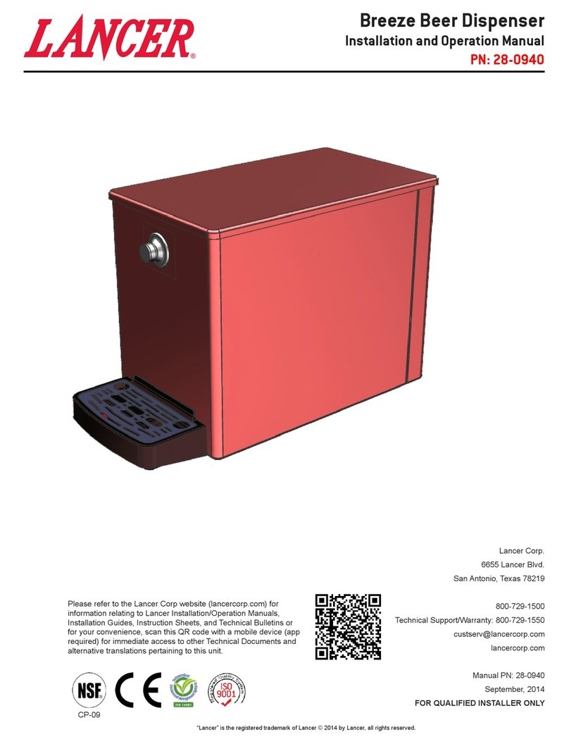
lancer Breeze Operating and maintenance instructions

ABOUT THIS MANUAL
This booklet is an integral and essential part of the product and
should be handed over to the operator after the installation and
preserved for any further consultation that may be necessary.
Please read carefully the guidelines and warnings contained
herein as they are intended to provide the user with essential
information for the continued safe use and maintenance of the
product. In addition, it provides GUIDANCE ONLY to the user on
the correct services and site location of the unit.
BEFORE GETTING STARTED
Each unit is tested under operating conditions and is thoroughly
inspected before shipment. At the time of shipment, the carrier
accepts responsibility for the unit. Upon receiving the unit,
carefully inspect the carton for visible damage. If damage exists,
have the carrier note the damage on the freight bill and le a
claim with carrier. Responsibility for damage to the dispenser lies
with the carrier.
The installation and relocation, if necessary, of this product must be carried out by qualied personnel with
up-to-date safety and hygiene knowledge and practical experience, in accordance with current regulations.
IMPORTANT SAFETY INSTRUCTIONS
LANCER PN: 28-0940/01
This unit is not a toy. Children should be advised not to play with appliance. It should not be used by children or inrm persons
without supervision. This appliance is not intended for use by persons (including children) with reduced physical, sensory or mental
capabilities, or lack of experience and knowledge, unless they have been given supervision or instruction concerning use of the
appliance by a person responsible for their safety. Cleaning and user maintenance shall not be performed by children without
supervision. This unit is not designed to dispense dairy products. The min/max ambient operating temperature for the dispenser is
35°F to 75°F (1.67°C to 23.89°C). Do not operate unit below minimum ambient operation conditions. Should freezing occur, cease
operation of the unit and contact authorized service technician. Service, cleaning and sanitizing should be accomplished only
by trained personnel. Applicable safety precautions must be observed. Instruction warnings on the product being used must be
followed.
! Intended Use Warning
®
CP-09
FOR QUALIFIED INSTALLER ONLY. This basic Installation Sheet is an initial release. If a complete Operations
Manual (for the unit being installed) is required or needed, please refer to the Lancer web site (lancercorp.com) for
immediate access, or for your convenience, scan this QR code with a mobile device (app required) for immediate
access to other Technical Documents and alternative translations (if available) pertaining to this unit. Contact Lancer
Customer Service for assistance as required.
Breeze Beer Dispenser
LANCER INSTALLATION GUIDE

2
DIMENSIONS
Width: 11.57 inches (294 mm)
Depth: 19.77 inches (502 mm)
Height: 15.54 inches (395 mm)
SPECIFICATIONS
This unit emits a sound pressure level below 70 dB
WEIGHT
Shipping: 55 lbs (24.95 kg)
Empty: 50 lbs (22.68 kg)
Ice Capacity: 19.4 lbs (8.8 kg)
PRODUCT SUPPLY
Minimum Pressure: 42 PSI (0.289 MPA)
Maximum Pressure: 46 PSI (0.317 MPA)
FITTINGS
Product Inlet: 5/16 inch barb
Your Service Agent:
Service Agent Telephone Number:
Serial Number:
Model Numer:
This manual was developed by the Lancer Corporation as a reference for the owner/operator and installer of this
dispenser. Please read this guide before installation and operation of this dispenser. If service is required please call your
Lancer Service Agent or Lancer Customer Service. Always have your model and serial number available when you call.
READ THIS MANUAL

3
INSTALLATION
Unpacking the Dispenser
1. Cut steel band and remove.
2. Remove plywood shipping base from unit.
3. If leg kit has been provided, assemble legs by tilting unit.
Selecting/Preparing Counter Location
DO NOT LAY UNIT ON ITS SIDE OR BACK
! ATTENTION
Inspect unit for concealed damage. If evident, notify
deliveringcarrierandleaclaimagainstthesame.
NOTE
The drain spider is located to the left side near the front
of the bin. The coldplate has a cavity designed to hold
the drain spider. During shipment or installation, the
drain spider may become dislodged from its original
position.Prior to installing the dispenser, ensure the
drain spider is in the correct position.This will prevent
drain clog issues. Inspect the lower bin area to ensure
the drain spider is secure in the coldplate cutout. If the
drain spider is not in place, locate the drain spider and
reinstall in the cold plate cavity where drain line exists.
Drain Spider
In order to facilitate proper dispenser drainage, ensure
that the dispenser is level, front to back and side to
side. Place a level on the top of the rear edge of the
dispenser. The bubble must settle between the level
lines. Repeat this procedure for the remaining three
sides. Level unit if necessary. For optimum
performance place the unit at a 0° tilt.
Leveling the Dispenser
If unit is to be transported, it is advisable to leave the
unit secured to the plywood shipping base.
NOTE
1. Connecting lines can be run through the front of the unit and
can extend down through a counter cutout.
2. Select a level, well ventilated, accessible location away from
direct sunlight (avoid) or overhead lighting.
3. The selected location should be able to support the weight of
the unit with the ice after counter cut out is made.
The dispenser should only be installed in a location
where it can be overseen by trained personnel
NOTE
NSF listed units must be sealed to the counter or have
four (4) inch legs installed.
NOTE
Dispenser Installation
1. Remove Top Cover.
2. Connect Product supply line to 3/8 inch barb tting located at
the front of the unit.
3. Connect other end of Product supply line to keg coupler
using 3/8 inch barb tting
4. Attach keg coupler on to the keg by turing clockwise until it
stops. Check for leaks.
5. Install the ice bin drain hose; connect the 90° elbow or
straight tting underneath the unit’s base. The ice bin drain
is located towards the front of the bin and slightly to the left.
Connect the hose. Extend the hose to an open type drain.
Drain line must be insulated with a closed cell
insulation. Insulation must cover the entire length of
thedrainhose,includingttings.Thedrainshouldbe
installed in such a manner that water does not collect
in sags or other low points, as condensation will form.
! CAUTION
The ice used in this unit may NOT be potable and
should not be ingested. DO NOT eat, chew, such,
swallow, or put into any drinks. The ice used in this
unit is intended solely for the refrigeration purposes
of the product.
! CAUTION
Pouring hot water down the drain may cause the Drain
Tube to collapse. Allow only luke warm or cold water to
enter the Drain Tube. Pouringcoee,tea,orother
similar substances down the drain may cause the Drain
Tube to become clogged.
! ATTENTION
6. Fill unit with ice and Install Top Cover and Drip Tray.

4
If a powder sanitizer is used, dissolve it thoroughly with hot water prior to adding to the product system. Ensure
sanitizing solution is removed from the dispenser as instructed. Avoid getting sanitizing solution on circuit boards. Do
not use strong bleaches or detergents; These can discolor and corrode various materials. Do not use metal scrapers,
sharp objects, steel wool, scouring pads, abrasives, or solvents on the dispenser. Do not use hot water above 140° F
(60° C). This can damage the dispenser.
! CAUTION
CLEANING AND SANITIZING
General Information
• Lancer equipment (new or reconditioned) is shipped from the factory cleaned and sanitized in accordance with NSF guidelines.
The operator of the equipment must provide continuous maintenance as required by this manual and/or state and local health
department guidelines to ensure proper operation and sanitation requirements are maintained.
• Cleaning should be accomplished only by trained personnel. Sanitary gloves are to be used during cleaning operations. Applicable
safety precautions must be observed. Instruction warnings on the product being used must be followed.
ThecleaningproceduresprovidedhereinpertaintotheLancerequipmentidentiedbythismanual.Ifotherequipmentis
being cleaned, follow the guidelines established by the manufacturer for that equipment.
NOTE
Cleaning Solution
Mix a mild, non-abrasive detergent (e.g. Sodium Laureth Sulfate, dish soap) with clean, potable water at a temperature of 90°F
to 110°F (32°C to 43°C). The mixture ratio is one ounce of cleaner to two gallons of water. Prepare a minimum of ve gallons of
cleaning solution. Do not use abrasive cleaners or solvents because they can cause permanent damage to the unit. Ensure rinsing
is thorough, using clean, potable water at a temperature of 90°F to 110°F. Extended lengths of product lines may require additional
cleaning solution.
Sanitizing Solution
Prepare the sanitizing solution in accordance with the manufacturer’s written recommendations and safety guidelines. The type
and concentration of sanitizing agent recommended in the instructions by the manufacturer shall comply with 40 CFR §180.940.
The solution must provide 100 parts per million (PPM) chlorine (e.g. Sodium Hypochlorite or bleach) and a minimum of ve gallons
of sanitizing solution should be prepared.
Excessive foaming is caused by a nearly empty beer
keg. Replace it with a new keg as soon as possible.
When a beer keg becomes completely empty, CO2gas
will blow out of the beer tap and splash beer.
NOTE
Wash the keg joint with water if necessary.
NOTE
Check that the beer tap lever is closed. Opening the keg
coupler with the beer tap lever open will cause beer to
splash out.
NOTE
Replace Beer Keg
1. Close the beer circuit by turning the keg coupler handle
counter-clockwise until it stops.
2. Turn the keg coupler further counter-clockwise and remove it
from the keg.
3. Remove empty keg.
4. Attach the keg coupler on the new keg by turning clockwise.
5. Open the beer circuit by turning the keg coupler clockwise
until it stops.
6. Set a mug (container) to recieve beer and push the beer tap
lever hard to the back (Foam Position). Keep pushing it to
dispense foam. When the mug is half lled with foam, move
lever back to original (Stop) position.
7. Wait for more than a minute to settle beer in circuit.
8. Set mug (contianer) and pull the beer tap lever toward you
to dispense beer. Keep dispensing beer until foam turns to
liquid.

5
Following sanitization, rinse with end-use product
until there is no aftertaste. Do not use a fresh water
rinse. This is a nsf requirement. Residual sanitizing
solution left in the system creates a health hazard.
! CAUTION Following sanitization, rinse with end-use product
until there is no aftertaste. Do not use a fresh water
rinse. This is a nsf requirement. Residual sanitizing
solution left in the system creates a health hazard.
! CAUTION
Daily Cleaning
1. Using the cleaning solution, clean Top Cover and all exterior
stainless steel surfaces.
2. Clean exterior of dispensing valves.
3. Remove Drip Tray by lifting to release its mounting holes
from the mounting screws.
4. Dump water and beer, and wash the Drip Tray and Splash
Plate with cleaning solution.
5. Lift the Drip Tray to hook the mounting holes on the mount-
ing screws, and set Splash Plate on the Drip Tray.
6. Wipe clean all splash areas using a damp cloth soaked in
cleaning solution.
7. Remove the beer tap by loosening the union nut by turning it
clockwise.
8. Tilt the beer tap toward you, and run cleaning solution
through the beer tap.
9. Ret the beer tap by turning the union nut counterclockwise.
Cleaning & Sanitizing Product Components
Lancer recommends regular maintenance and sanitization of product lines. Beer lines and taps should be routinely
cleaned as recommended by the local authorities, beer manufacturer or manufacturer of the chemical cleaner used.
Follow manufacturers’ instructions for proper use of sanitizing (or detergent) products such as recommended use-
dilution, material compatibility, storage, shelf-life, and safe use and disposal.
Ice Bin Cleaning - Start Up and Monthly
1. Remove Top Cover.
2. Remove Drip Tray by lifting it up and out from the dispenser
face.
3. Using cleaning solution, described on previous page, and
a clean cloth or soft brush, clean all sides of Ice Bin and
surface of aluminum casting.
4. Repeat Step 3 for all exterior surfaces of the unit.
5. Using hot water, thoroughly rinse away the cleaning solution.
6. Wearing sanitary gloves, soak a clean cloth towel in
sanitizing solution, described on the previous page, and
wash all sides of Ice Bin and surface of aluminum casting.
7. Repeat Step 6 for all metal and plastic surfaces (but not
labels) of the unit exterior.
8. Wearing sanitary gloves, reassemble all removable parts.
9. Fill Unit with ice and replace Top Cover.
To prevent possible harm to the environment from improper disposal, recycle the unit by locating an
authorized recycler or contact the retailer where the product was purchased. Comply with local regulations
regarding disposal of the refrigerant and insulation.
Dispenser Disposal

6
ILLUSTRATIONS & PART LISTINGS
Item Part No. Description
1 30-11859 Cup Rest, Breeze Beer
2 01-2976 Elbow, Connector, JG, 3/8”X5/16”
3 05-3266 Drip Tray, Breeze Beer
4 04-1682 (2) Screw, M4-0.7X4.5, 4.5 Shoulder, FHD, PH, SS
5 30-11833 Lid, Metal, Breeze Beer
1
3
2
4
5

7
INTENTIONALLY LEFT BLANK
Table of contents
Other lancer Kitchen Appliance manuals
Popular Kitchen Appliance manuals by other brands

Lakeland
Lakeland MyKitchen 13666 user manual

DURALON
DURALON nuwave BLUE 31425 owner's manual

Scarlett
Scarlett SC-FD421001 instruction manual

Melissa
Melissa 643-036 instruction manual

Electrolux
Electrolux EKM7 Series Instruction book

North American
North American BB12482G / TR-F-04-B-NCT-1 Assembly and operating instructions