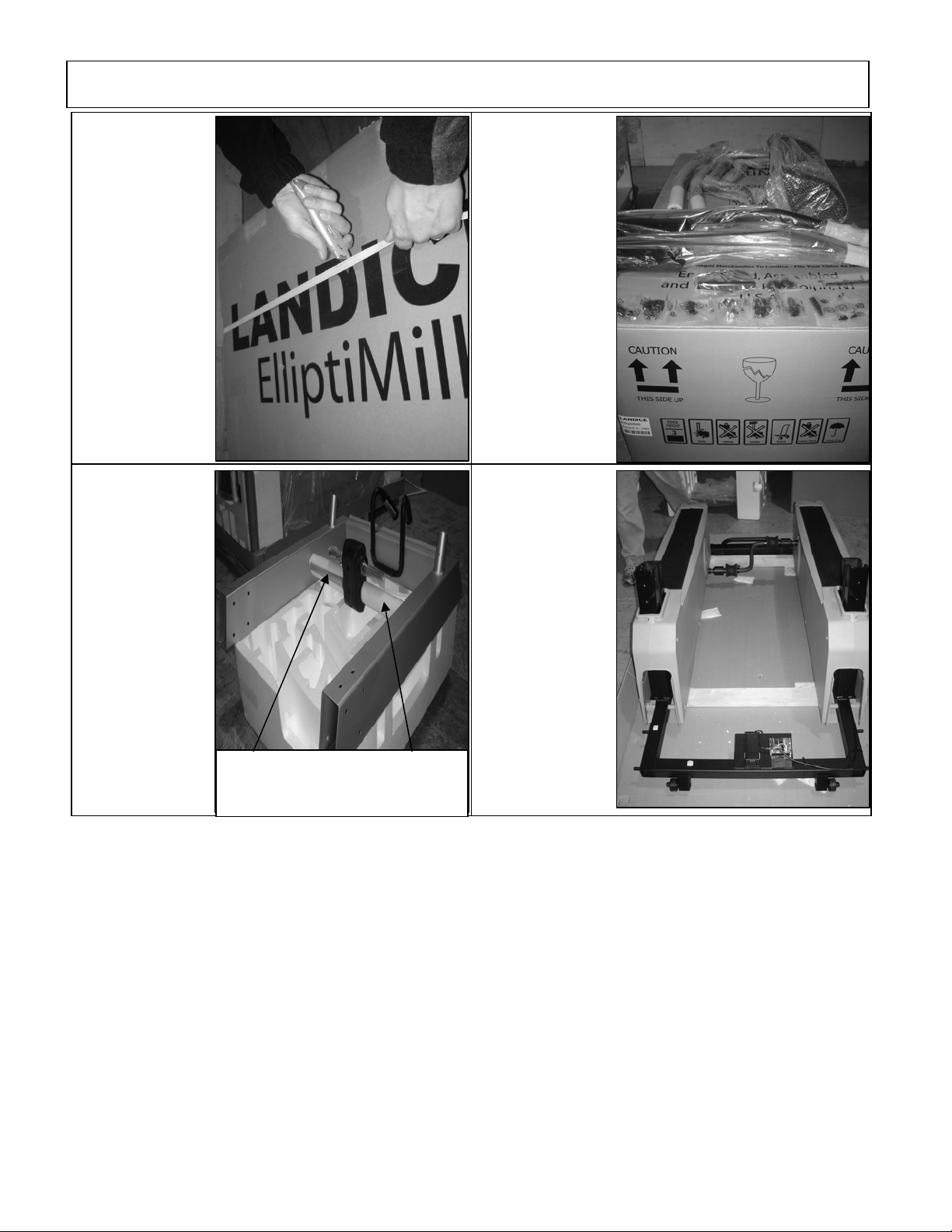
5. Check that all
the leveling feet (6)
are turned all the
way up into the
frame by tilting the
machine and
adjusting them as
shown. Attempt to
rock the unit back
and forth to check
for stability. If
unstable, adjust
the feet until it
stabilizes.
6. Slide the
vertical stride
adjustment
members into the
upright housing.
DO NOT REMOVE
the plastic wrap /
froam that secures
the two arms
together. NOTE:
There is a
difference between
right and left ("L" /
"R" decals).
7. Open hardware
bag "STEP 1".
Use the big flat
washer, lock
washer and bolt to
fasten the vertical
stride adjustment
members. After
firmly tightening,
cap the tubes with
the large black
dome finish plugs
to conceal the
hardware.
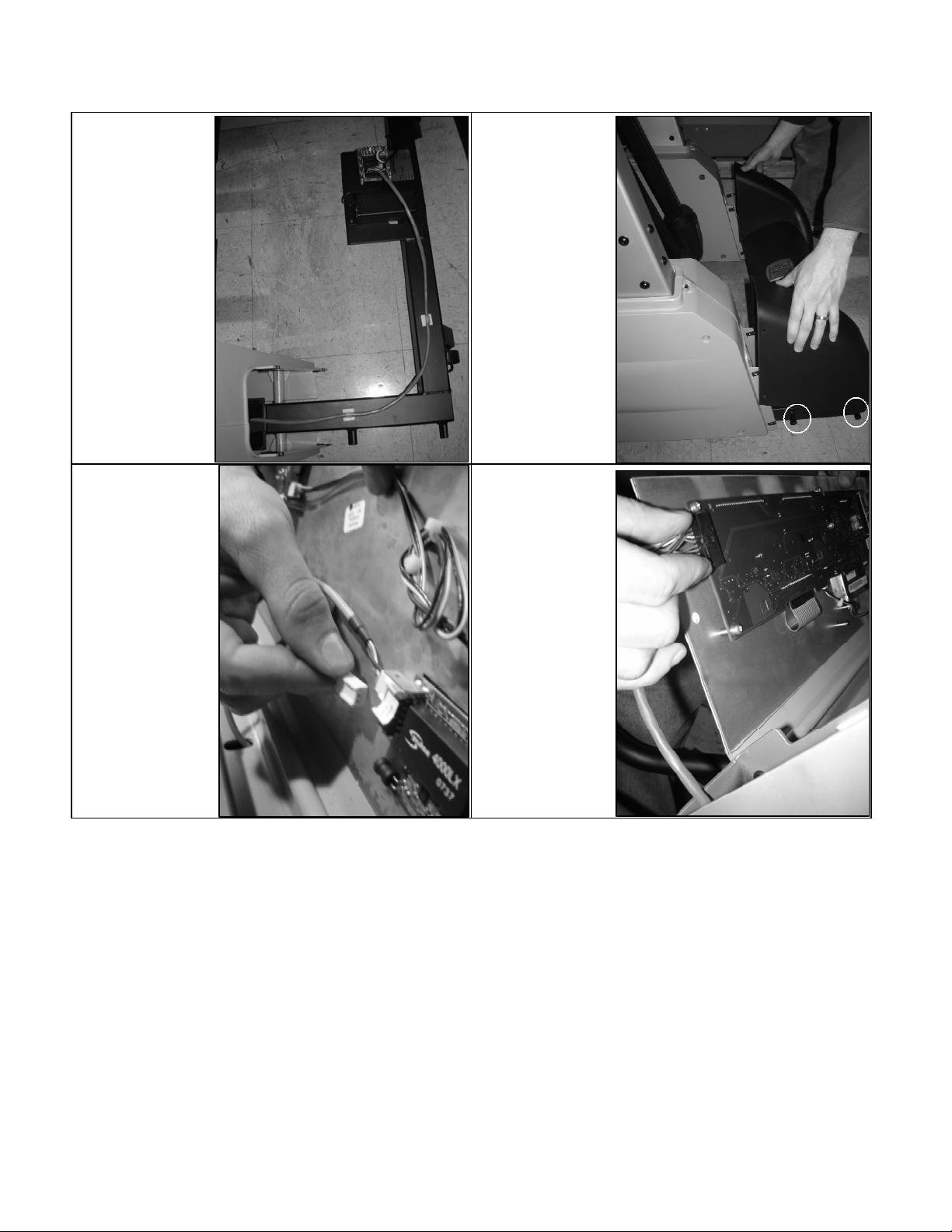
8. Place the
protective
cardboard over the
frame as shown in
the picture.
Tip: Remove the bearing caps
afterwards to avoid accidental upright
scratching
Note: Save the remaining black
screws in hardware bag “STEP 1”.
You will need them after mounting
the u
ri
ht “STEP 12”.