Landis+Gyr E65C User manual

Communication
Industrial and Commercial
CU-P40, P41, P42
E65C
User Manual
[STATUS]
E65C CU-P40, P41, P42 communication units provide
GSM/GPRS communication between E650 or E850 meters and a central system.
Date: 22.10.2013
File name: D000043188 E65C CU-P4x User Manual en d
© Landis+Gyr
D000043188 en d

2/40 [Status] Revision history
© Landis+Gyr D000043188 en d –E65C –CU-P40, P41, P42 –User Manual
Revision history
Version
Date
Comments
a
15.03.2012
First edition (derived from user manual E65C CU-P30, P31, P32 D000011691)
b
01.03.2013
Cover picture replaced.
Section 4.4.1 Connecting the antenna updated.
Section 4.4.3 Choosing the most suitable antenna position in GPRS mode
updated.
c
12.03.2013
Synchronized document versions in all languages.
d
22.10.2013
Replace ETSI standard with 3GPP release 4.
Excessive power failure warning. D72 CU-P4x firmware release. LED signal
strength in GPRS mode. Safety info. Antenna selection.
Nothing in this document shall be construed as a representation or guarantee in respect of
the performance, quality or durability of the specified product. Landis+Gyr accepts no liability
whatsoever in respect of the specified product under or in relation to this document.
Subject to change without notice.

Table of contents 3/40
D000043188 en d –E65C –CU-P40, P41, P42 –User Manual © Landis+Gyr
Table of contents
Revision history ...................................................................................................................................2
Table of contents .................................................................................................................................3
About this document............................................................................................................................5
1Device description......................................................................................................................6
1.1 Scope of application................................................................................................................6
1.2 Characteristics ........................................................................................................................6
1.3 Type designation.....................................................................................................................6
1.4 Functions ................................................................................................................................7
1.4.1 GSM/GPRS modem ..........................................................................................................7
1.4.2 CS interface.......................................................................................................................7
1.4.3 RS232 interface.................................................................................................................7
1.4.4 RS485 interface.................................................................................................................7
2Safety...........................................................................................................................................8
2.1 Safety information...................................................................................................................8
2.2 Responsibilities.......................................................................................................................8
2.3 Safety regulations ...................................................................................................................9
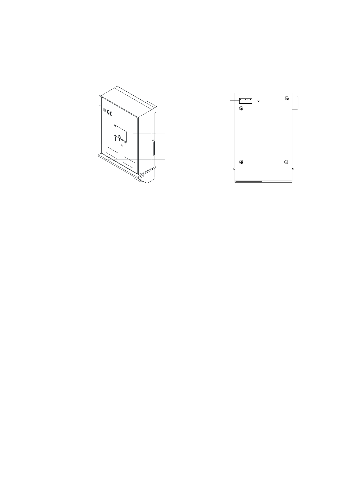
3Mechanical construction..........................................................................................................10
3.1 Overview...............................................................................................................................10
3.2 Power supply, antenna and interface connections.................................................................11
3.2.1 Connections CU-P40.......................................................................................................11
3.2.2 Connections CU-P41.......................................................................................................12
3.2.3 Connections CU-P42.......................................................................................................13
3.3 Faceplate..............................................................................................................................14
3.4 LEDs.....................................................................................................................................14
4Installation/De-installation .......................................................................................................15
4.1 Inserting a SIM-card..............................................................................................................15
4.2 Fitting in meter ......................................................................................................................15
4.3 Fitting in CU-adapter CU-ADP2.............................................................................................18
4.4 Connecting the communication unit.......................................................................................19
4.4.1 Connecting the antenna...................................................................................................19
4.4.2 Choosing the most suitable antenna position in GSM mode ............................................21
4.4.3 Choosing the most suitable antenna position in GPRS mode ..........................................22
4.4.4 Connecting the CS interface............................................................................................25
4.4.5 Connecting the RS485 interface......................................................................................26
4.4.6 Connecting the RS232 interface......................................................................................26
4.4.7 Connecting the external 5 V power supply for series 2 or older meters............................28
4.4.8 Connecting the external 5 V power supply for series 3 meters.........................................29
4.4.9 Final operations...............................................................................................................30
4.5 Commissioning and functional check ....................................................................................31
4.6 Removal/Exchange of communication unit............................................................................31
5Operation ..................................................................................................................................32
5.1 LED status description pre D72 firmware ..............................................................................32
5.2 LED status description D72 firmware ....................................................................................32
5.3 Wrong PIN code....................................................................................................................34
5.4 Signal strength indication using LEDs...................................................................................34
6Service.......................................................................................................................................35
6.1 Troubleshooting ....................................................................................................................35
6.2 Repairing the communication unit .........................................................................................35

4/40 [Status] Table of contents
© Landis+Gyr D000043188 en d –E65C –CU-P40, P41, P42 –User Manual
6.3 Repairing the 5 V power supply............................................................................................ 36
7Maintenance............................................................................................................................. 37
8Disposal.................................................................................................................................... 38
9Index ......................................................................................................................................... 39

About this document 5/40
D000043188 en d –E65C –CU-P40, P41, P42 –User Manual © Landis+Gyr
About this document
The present user manual applies to communication units E65C CU-P40,
CU-P41 and CU-P42 –designated CU-P4x below.
This user manual supplements the operating instructions of the meter and
of the CU-adapter E65C CU-ADP2 and is incomplete without the data
contained therein. Together with these operating instructions, the user
manual contains all the information necessary for the operation of the
CU-P4x communication unit for the intended purpose. This includes:
Provision of knowledge concerning characteristics, construction and
function of the communication unit CU-P4x
Information about possible dangers, their consequences and meas-
ures to prevent any danger
Details concerning the performance of all work throughout the service
life of the communication unit CU-P4x (installation, commissioning,
operation, maintenance, shutting down and disposal)
The contents of this user manual are intended for technically qualified per-
sonnel of energy supply companies responsible for the system planning,
installation and commissioning, operation, maintenance, decommissioning
and disposal of the meters.
The technical data and the functional description of the communication unit
CU-P4x can be found in the following documents:
D000043185 "Technical Data E65C CU-P40, P41, P42"
D000011460 "Functional Description E65C CU A, B, M, G, D, P, E, Q"
D000039353 "User Manual E65C CU-ADP2"
Range of validity
Purpose
Target group
Reference documents

6/40 Device description
© Landis+Gyr D000043188 en d –E65C –CU-P40, P41, P42 –User Manual
1 Device description
1.1 Scope of application
The communication unit CU-P4x can be fitted in and removed from the fol-
lowing Landis+Gyr meters without opening the calibration seal:
Landis+Gyr E650 ZxD300/400xTindustrial and commercial meters
Landis+Gyr E850 ZxQ high-precision meters
Inserted in a CU-adapter CU-ADP2, the communication unit CU-P41 or
CU-P42 can also be used with other meters (e.g. Landis+Gyr E650
ZxD300/400xR, ZMD100AR, ZxB or meters from other manufacturers).
Connection to the meter is made in this case via an interface in the
communication unit (CS, RS232 or RS485).
1.2 Characteristics
The communication unit CU-P4x contains a built-in GSM/GPRS modem
(mobile telephone modem with GPRS service for data transmission in
packet form in GSM networks) and, depending on the version, an RS232-
and a CS interface (CU-P41) or an RS485- and a CS interface (CU-P42).
It is used to supplement the meters listed above.
The GSM/GPRS modem serves to read out or re-parameterise the meters
from a central station via the mobile telephone network with GPRS via the
Internet. It can also be used as a normal GSM modem.
The RS485 and CS interfaces can be used for connecting meter points
over a relatively long distance compared to RS232. The CS interface can
be parameterised as an active or passive interface and thus can be used
as master or slave as required with multiple connections.
If a communication unit CU-P41 or CU-P42 is used externally in a CU-adapter,
one of the existing interfaces of the communication unit is required for connec-
tion to the meter.
1.3 Type designation
The type designation of the communication unit CU-P4x is added to that of
the meter (see meter user manual), but is not shown on the main faceplate
of the meter. It is specified directly on the case of the communication unit
and can be seen through the front door of the meter through an opening on
the tariff faceplate.
The communication unit CU-P4x is available in the following versions:
Type
GSM/GPRS
modem
RS232
RS485
CS+
CU-P40
CU-P41
CU-P42

Device description 7/40
D000043188 en d –E65C –CU-P40, P41, P42 –User Manual © Landis+Gyr
1.4 Functions
A functional description of the communication unit CU-P4x is provided
separately. The following main functions are briefly summarised below.
1.4.1 GSM/GPRS modem
The mode of operation can either be parameterised as GSM modem or as
GPRS modem.
The GSM modem (GSM = Global System for Mobile Communication) is
approved according to various standards such as 3GPP release 4. It is a
wireless modem (Modulator-Demodulator) for the modulated remote
transmission of data via the mobile telephone network. The GSM modem
uses the 850 MHz, 900 MHz, 1800 MHz and 1900 MHz GSM frequency
bands.
The GPRS modem (GPRS = General Packet Radio Service) uses the
GSM network for data transmission, but sends and receives the data in
packets. The packet-oriented data transmission permits network usage
billing based on data volumes transmitted instead of connection time.
GPRS permits a wireless connection to the Internet by means of transmis-
sion protocol TCP/IP (Transmission Control Protocol/Internet Protocol).
1.4.2 CS interface
The serial bi-directional CS interface is standardised to IEC 62056-21 or
DIN 66258. It supports both the communication protocol to IEC 62056-21
as well as communication according to dlms and can be operated both
actively and passively.
1.4.3 RS232 interface
The RS232 interface is an asymmetrical, serial, asynchronous, bi-direc-
tional interface to DIN 66259. This interface can be used for the (tempo-
rary) connection of a PC or laptop, in order to communicate with the meter
independent of normal data acquisition. The RS232 interface of the com-
munication unit CU-P41 has no control lines (3-wire version).
1.4.4 RS485 interface
The serial bi-directional RS485 interface is standardised to ISO-8482. It is
basically intended for the connection of several meters (up to 31) using the
CU-P42 as the master.

8/40 Safety
© Landis+Gyr D000043188 en d –E65C –CU-P40, P41, P42 –User Manual
2 Safety
2.1 Safety information
The following symbols are used to draw your attention to the relevant
danger level, i.e. the severity and probability of any danger, in the individual
sections of this document.
Danger
Identifies an extraordinarily great and immediate danger that could lead to
serious physical injury or death.
Warning
Indicates a potentially hazardous situation that may result in minor physical
injury or material damage.
Note
Indicates general details and other useful information to help you with your
work.
In addition to the danger level, safety information also describes the type
and source of the danger, its possible consequences and measures for
avoiding the danger.
2.2 Responsibilities
The owner of the communication units –usually the utility company –is
responsible for assuring that all persons engaged in working with meters:
Have read and understood the relevant sections of the user manual.
Are appropriately qualified for the work to be performed in accordance
with national regulations (see ISSA "Guideline for Assessing the Com-
petence of Electrically Skilled Persons").
Strictly observe the safety regulations (laid down in section 2.3) and
the operating instructions as specified in the individual sections.
In particular, the owner of the communication units bears responsibility for
the protection of persons, prevention of material damage and the training of
personnel.
For this purpose, Landis+Gyr provides training on a variety of products and
solutions. Please contact your local Landis+Gyr representative if interested.

Safety 9/40
D000043188 en d –E65C –CU-P40, P41, P42 –User Manual © Landis+Gyr
2.3 Safety regulations
The following safety regulations must be observed at all times:
Changing of the communication unit or the 5 V supply in the terminal
cover used under special conditions or the GSM antenna must only be
made on meters not under voltage.
Only appropriate tools shall be used for the job. This means, e.g. that
the screwdriver must be of the correct size for the screws, and the
handle of the screwdriver must be insulated.
Devices which have fallen down should not be installed, even if no
damage is apparent, and should be returned for testing to an author-
ised service centre (internal damage possible).
Communication units must not be cleaned under running water or with
compressed air. Water ingress can cause short-circuits or damage
components.
Antenna installation must conform to instructions listed in this
document.
In addition, the safety instructions given in the user manuals for the meter
and the CU-adapter CU-ADP2 are also applicable.

10/40 Mechanical construction
© Landis+Gyr D000043188 en d –E65C –CU-P40, P41, P42 –User Manual
3 Mechanical construction
3.1 Overview The communication unit CU-P4x is a unit complete in itself with its own
plastic case.
99715479-2
2012
CU-P42
CONGSM
RX
TX
CU-P
42
GSM/GRPS
C S
RS485
24
2
3
+-
5V
1
5
2
4
3
1
Fig. 3.1 Communication unit CU-P4x, removed
1 10-pin connector
2 Faceplate
3 SIM-card slot
4 Light guide through which the LEDs are visible
5 Power supply, antenna and interface connections
The faceplate of the communication unit fitted in the meter is visible with
the meter front door open. When fitted in a CU-adapter, the faceplate can
be seen through the transparent front cover.
The external connections (supply voltage, antenna, CS- and RS485 or
RS232 interface) are situated underneath, while a 10-pin connecting plug
provides connection at the rear with the meter electronics or CU-adapter.
Four LEDs on the circuit board indicate transmission and reception activi-
ties as well as readiness to receive through the light guide under the face-
plate.
The communication unit has no seal of its own. It is secured when built-in
by a utility seal of the meter or CU-adapter.

Mechanical construction 11/40
D000043188 en d –E65C –CU-P40, P41, P42 –User Manual © Landis+Gyr
3.2 Power supply, antenna and interface connections
The socket for the external 5 V supply is provided on all communication
units CU-P4x. To ensure reliable modem operation, the use of an external
5 V power supply is recommended for E650 meters in some cases. Please
refer to section 4.4.7 and 4.4.8 for addition information.
With the screwless spring-loaded terminals of the CS interface (only pre-
sent on CU-P41 and CU-P42) the polarities are determined as follows:
+ left terminal (23)
–right terminal (24)
The pins of the RJ12 socket (only present on CU-P41 and CU-P42) are
numbered as follows:
1
6
Fig. 3.2 Pin numbering of RJ12 socket
3.2.1 Connections CU-P40
1 2
Fig. 3.3 Connections CU-P40
1 Input external 5 V power supply (2-pin socket)
2 Antenna connection (MCX socket)
Fig. 3.4 Connection diagram communication unit CU-P40

12/40 Mechanical construction
© Landis+Gyr D000043188 en d –E65C –CU-P40, P41, P42 –User Manual
3.2.2 Connections CU-P41
1 2 3 4
Fig. 3.5 Connections CU-P41
1 Input external 5 V power supply (2-pin socket)
2 CS interface (screwless spring-type terminals WAGO)
3 Antenna connection (MCX socket)
4 RS232 interface (RJ12 socket)
The RJ12 socket of the RS232 interface has the following pin assignment:
Pin No.
Terminal
Signal
2
TxD
Transmitted Data
3
GND
Signal Ground
5
RxD
Received Data
Fig. 3.6 Connection diagram communication unit CU-P41

Mechanical construction 13/40
D000043188 en d –E65C –CU-P40, P41, P42 –User Manual © Landis+Gyr
3.2.3 Connections CU-P42
1 2 3 4
Fig. 3.7 Connections CU-P42
1 Input external 5 V power supply (2-pin socket)
2 CS interface (screwless spring-type terminals WAGO)
3 Antenna connection (MCX socket)
4 RS485 interface (RJ12 socket)
The RJ12 socket of the RS485 interface has the following pin assignment:
Pin No.
Terminal
Signal
1
c
Signal Ground
2
a
Data a
3
b
Data b
4
b
Data b
5
a
Data a
6
c
Signal Ground
Fig. 3.8 Connection diagram communication unit CU-P42

14/40 Mechanical construction
© Landis+Gyr D000043188 en d –E65C –CU-P40, P41, P42 –User Manual
3.3 Faceplate
The faceplate of the communication unit CU-P4x has the following appear-
ance depending on version:
1
3
4
5
99 715 479-2
2012
C O NRXTX
2
6
7 CU-P42
G S M
CU-P42
CU-P42
GSM/GPRS
RS485
CS
23
5V
24
+-
Fig. 3.9 Faceplate of the communication unit CU-P4x (example CU-P42)
1 Serial number
2 Year of construction
3 Diagram
4 dlms symbol depending on parameterisation
5 Designation of transmit/receive LEDs
6 Insulation class and CE mark
7 Type designation
The faceplate may contain other country-specific data, e.g. warnings, etc.
3.4 LEDs
The four LEDs TX, RX, CON and GSM designated on the faceplate are
fitted on the circuit boards and can be seen through the light guide below
the faceplate. Their function is described in section 5 "Operation".

Installation/De-installation 15/40
D000043188 en d –E65C –CU-P40, P41, P42 –User Manual © Landis+Gyr
4 Installation/De-installation
4.1 Inserting a SIM-card
Insert a SIM-card in the communication unit as follows:
1. If present, remove a previously installed SIM-card by releasing it
(pushing it in) and withdrawing it.
2. Insert the SIM-card into the slot as shown below and gently push it in
until it engages. Once the SIM-card is properly inserted, it should not
extend beyond the side of the device.
Fig. 4.1 Correct insertion of the SIM-card
Keep SIM-card contacts clean
SIM-cards have electrical contacts that may come into contact with the user
during normal use. The presence of oils and dirt on these contacts may
cause corrosion on these contacts that are not apparent during the instal-
lation or shortly thereafter. Such corrosion may cause the contacts to
become unreliable and affect the option of the communication unit. It is
recommended that the user clean the contacts with a suitable solution or
perform the installation in a controlled clean environment to maximize the
operating life of the modem.
SIM with roaming disabled
It is possible to get SIM cards from Mobile Network Operators where
roaming is disabled. This is recommended in order to avoid higher service
charges when installing meters near the border of countries. There are
initialization commands that can also be added to the CU that can cause
the CU to select a pre-defined operator. This is the less preferred solution
and may cause GSM LED behaviour to change.
4.2 Fitting in meter
No voltage to meter when fitting
In order to avoid hazardous electric shocks, ensure there is no voltage
applied to the meter when fitting the communication unit. Contact with live
parts is dangerous to life. Disconnect the meter from the power supply as
described in the meter user manual.

16/40 Installation/De-installation
© Landis+Gyr D000043188 en d –E65C –CU-P40, P41, P42 –User Manual
Excessive Number of Power Failures reduces Life of Product
The CU writes to it internal FLASH memory every time that there is a power
failure. This type of memory has a life of approximately 100,000 write
cycles. This is not a guaranteed value. For a life of 15 years, that amounts
to approximately 15 power failures per day. Environments exceeding this
limit may shorten the useful life of the product.
Older version of CU should not be used in new meters
The CU is designed to be interoperable with all existing meters at the time
that it was designed. Once a device is obsolete and is replaced by a newer
version of the product, interoperability testing stops. This means that older
CU product that have been in the field for some number of years should not
be used with new meters even though they can be inserted into the meter.
Fit the communication unit in the meter as follows (with SIM-card inserted
according to section 4.1):
1. Ensure that no voltage is applied to the meter.
2. Remove the utility seals on the front door and terminal cover.
3. Open the front door and remove the terminal cover.
Fig. 4.2 Preparing the meter for fitting the communication unit
4. Remove the built-in "dummy" communication unit.
5. Insert the communication unit carefully at the place provided in the
meter. Ensure correct fitting of the connector.

Installation/De-installation 17/40
D000043188 en d –E65C –CU-P40, P41, P42 –User Manual © Landis+Gyr
Fig. 4.3 Fitting communication unit in meter
6. Close and seal the front door.

18/40 Installation/De-installation
© Landis+Gyr D000043188 en d –E65C –CU-P40, P41, P42 –User Manual
4.3 Fitting in CU-adapter CU-ADP2
No voltage to CU-adapter when inserting communication unit
There must be no voltage applied to the CU-adapter when the communi-
cation unit is inserted. Contact with live parts is dangerous to life. If neces-
sary, disconnect the CU-adapter from the power supply as described in the
CU-ADP user manual.
Fit the communication unit CU-P42 in the CU-adapter CU-ADP2 as follows:
1. Remove the utility seals on the front cover.
2. Remove the transparent front cover.
Fig. 4.4 Preparing the CU-adapter CU-ADP2 for fitting the communication unit
3. Insert the communication unit carefully at the position provided in the
CU-adapter by first moving this forwards under the cam and then
pressing down at the rear. Ensure the correct fit of the plug. The front
cover should only be replaced after connecting.
Fig. 4.5 Fitting communication unit in CU-adapter CU-ADP2
4. Connect the communication unit to the meter (via RS485, RS232 or
CS interface) and the adapter to mains and mount the front cover, see
User Manual of the CU-adapter.

Installation/De-installation 19/40
D000043188 en d –E65C –CU-P40, P41, P42 –User Manual © Landis+Gyr
4.4 Connecting the communication unit
4.4.1 Connecting the antenna
Connect the antenna of the communication unit CU-P4x as follows:
1. Insert the plug of the antenna cable from above in the antenna socket
of the communication unit.
Fig. 4.6 Connecting antenna
2. If necessary: File a small hole for the antenna cable in the terminal
cover at the required point with a round file.
3. Set up the antenna with magnetic base so that a good reception may
be expected (see following section 4.4.2 "Choosing the most suitable
antenna position in GSM mode").
Antenna cable
Ensure that there are no physical forces acting on the antenna cable.
The antenna plug fitted on the circuit board could otherwise be torn off.
Always operate with an Antenna
The CU should only be operated with an antenna. Operating without an
antenna for extended periods of time is not advised. Failure to do so may
violate electromagnetic emission regulations, unreliable operation of device
or damage to device.
Do not operate device where Mobile Phone Operation is prohibited
The CU emits radio frequencies complying with EU R&TTE and EMC
directives. There are additional restrictions that may be locally imposed
such as hospitals and operating rooms where radio equipment is strictly
forbidden. In addition, areas where there is risk of explosions such as gas
stations and oil refineries.

20/40 Installation/De-installation
© Landis+Gyr D000043188 en d –E65C –CU-P40, P41, P42 –User Manual
Conforming to RTT&E Safety aspects
In order to comply with Specific Absorption Rate (SAR) specified as part
the RTT&E directive, the installation must fulfil the following points:
Antenna must not be installed directly (<1 m) beside people and
other equipment.
Antenna must have a gain less than or equal to 1.4 dBi at 850 MHz
and 900 MHz and a gain less than or equal to 3 dBi at 1800 MHz
and 1900 MHz.
Positioning of antenna
When setting up the antenna, movable objects such as doors and windows
should be positioned in the same way as when the meter is to be read. For
example, if doors will be closed after the installation during operation, the
signal strength is only valid when the door is closed. Avoid places where
moving metal objects can be found (e.g. cars in a garage).
The effect of weather on signal strength
Humidity, rain and lightning can affect signal strength measurements as
well as the frequency band being used. Additional margin beyond the
minimum signal level is needed to ensure reliable operation.
Other manuals for E65C
1
This manual suits for next models
3
Table of contents
Other Landis+Gyr Conference System manuals
Popular Conference System manuals by other brands

Viessmann
Viessmann Vitogate 200 Installation and service instructions for contractors

Avaya
Avaya CU-360 quick guide

Spirent communications
Spirent communications SR5500 Operation manual

Polycom
Polycom RealPresence Experience RPX HD user guide

Lucent Technologies
Lucent Technologies MERLIN LEGEND Release 7.0 Feature reference

Mitsubishi Electric
Mitsubishi Electric GOT 1000 Series user manual