ASSEMBLE WITH CARE! Pangard IIPolyester Powdercoat is a strong, long-lasting finish. To
protect this finish during assembly, place unwrapped powdercoated parts on packaging foam or
other non-marring surface. Do not place or slide powdercoated parts on concrete or other hard or
textured surface –this will damage the finish causing rust to occur. Use touch-up paint on any
gouges in the finish caused by assembly tools.
Assembly Guide
Backdrop posts, panels and connectors installation guide
www.landscapeforms.com Ph: 800.521.2546
Page 2 of 5
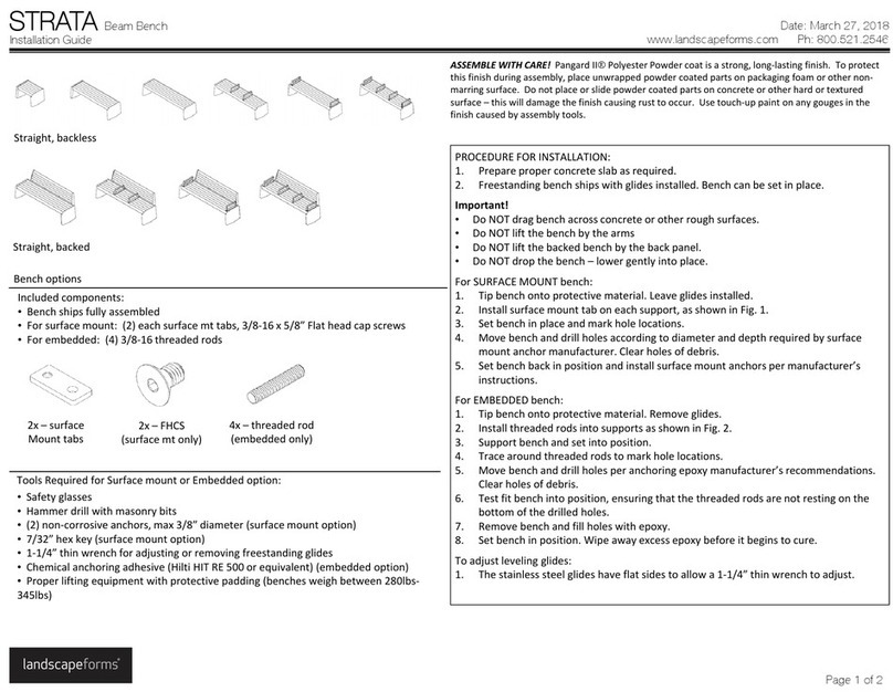
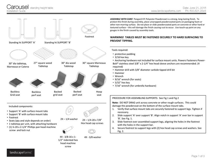
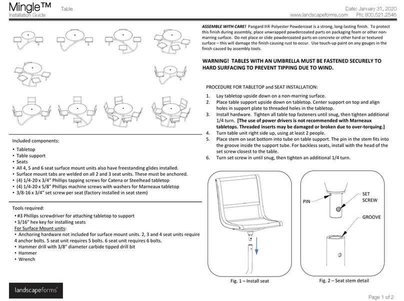
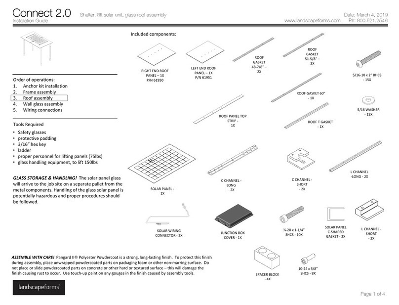
Tools required for assembly
•Safety glasses
•6ft level
•(4) anchors per post, max Ø1/2”.
•(4) anchors per L panel, max Ø1/2”
•masonry drill bit
•compressed air for clearing holes of debris
•1/8” hex key for cover plate
•3/16” hex key for attaching panels to posts
•1/4” wrench or socket for attaching green screen panels
•5/16” wrench or socket for attaching glass wall panels
•Phillips head screwdriver for attaching glass wall panels
•Glass handling equipment, if required
•Wiring tools and connectors if power garage is specified
INSTALLATION: Refer to specifier’s plan drawings for location and design of Backdrop.
1. Set first post in position. Brace post to stay in upright position.
2. Set second post in position. Brace post to stay in upright position.
3. Attach panels or top and bottom channels using 5/16-18 x 1-1/4” hex socket button
head cap screws and 5/16” washers:
•For glass wall panels, green screen panels and horizontal slat panels, attach
top and bottom channels to posts. Wall inserts will be attached after posts
are anchored. See Fig. 1.
•For angled vertical louver walls and perforated panels, top and bottom
channels are connected to wall panels. Full wall assembly is attached to the
posts. See Figs. 2 and 3.
•Attach connectors as specified, see Fig. 4.
•Post with power garage ships with power garage uninstalled. Conduit and
line-in wiring is provided by installer. Remove receptacle from power garage
assembly. Run line-in wiring up through conduit, out opening in post and in
through cord grip on power garage, see Fig. 10. Make connections to
receptacle. Reattach receptacle to power garage. Install power garage
assembly into opening in post, positioning as shown in Fig. 11. Attach power
garage to post from the backside of the post using (2) #12 x 7/8” hex head
tapping screws, dimensioned as shown in Fig. 11.
4. Repeat steps for attaching channels and posts for full layout.
5. Adjust location of wall as needed for final positioning.
6. Mark hole locations through base plates on posts.
7. Move wall assembly to allow access for drilling holes.
8. Drill all holes as required by anchor manufacturer’s recommendations.
9. Move wall assembly back into position and install anchors.
10. Retighten channel/wall hardware connections to posts.
11. Attach any glass, green screen or horizontal slat wall panels as specified.
•For horizontal slat panel, see Fig. 5.
•For green screen panel, see Fig. 6
•For glass wall panel, see Figs. 7, 8 and 9. Attach glass braces to posts. Attach
larger half of glass clamp to braces, ensuring all clamps face to the same side
and are parallel to the brace, see Fig. 8. Using proper glass handling
equipment, position glass panel on clamps. Attach back half of clamps with
screws provided, see Fig. 9. Do not overtighten.
12. Attach cover plates, see Fig. 12.
Date: February 9, 2023
