LANGER EMV-Technik ICS 105 User manual

2018.09.18 User manual ICS 105 IC scanner_en
User manual
ICS 105 set
IC Scanner 4-Axis Positioning System
Copyright © November 2013
LANGER EMV-Technik GmbH

- 2 / 25 -
LANGER
EMV-Technik
DE-01728 Bannewitz
mail@langer-emv.de
www.langer-emv.com
ICS 105 IC Scanner set
Content: Page
1Safety Instructions ....................................................................................................3
2Scope of Delivery ...................................................................................................... 4
3Technical Parameters................................................................................................ 5
4Intended Use..............................................................................................................7
5Measurement Set-up ................................................................................................. 8
5.1 Installing the GND 25 holder ......................................................................................................8
5.2 Installing the Groundplane GND 25 ...........................................................................................8
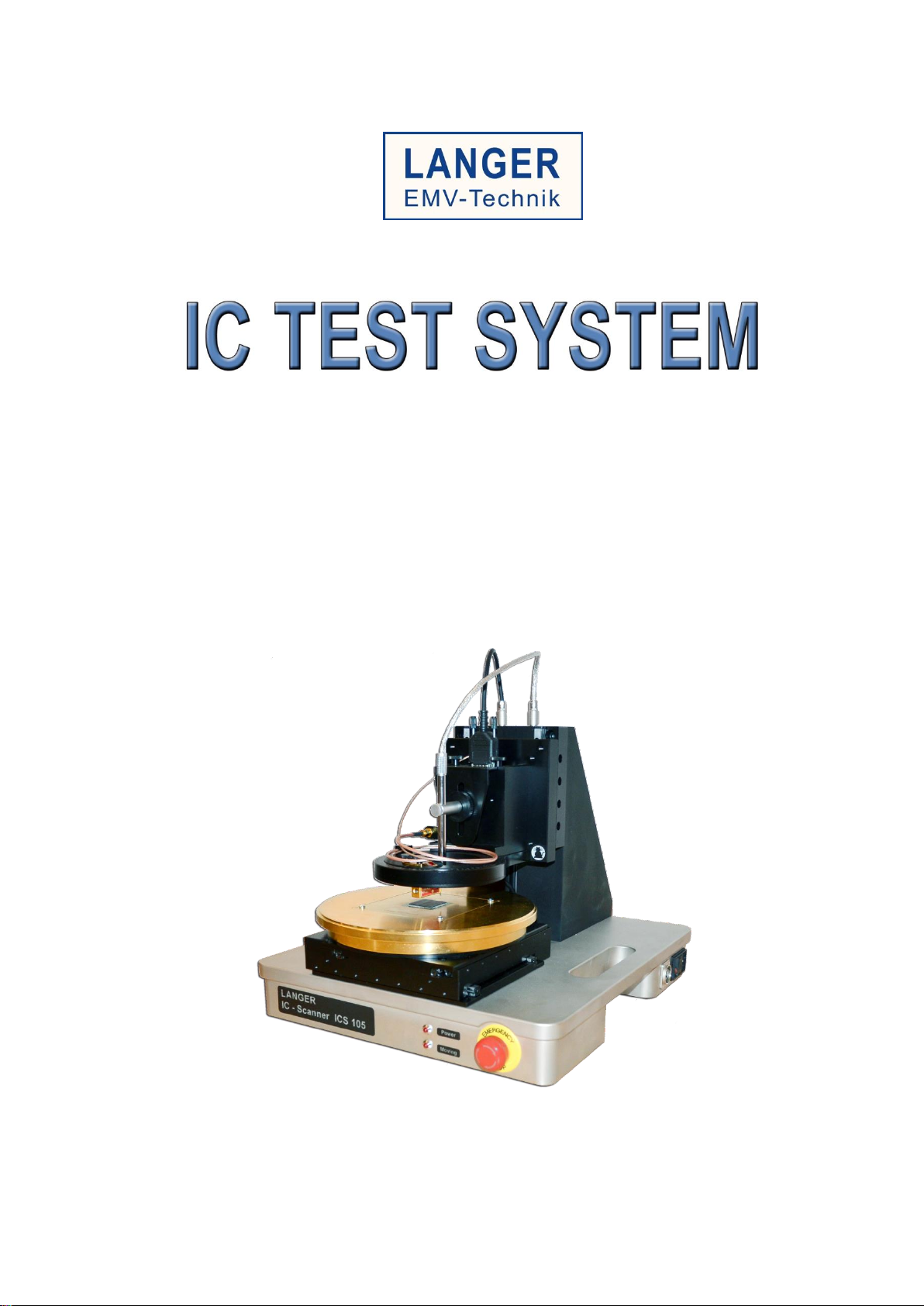
5.3 Installing the DM-CAM holder.3 Camera Holder........................................................................9
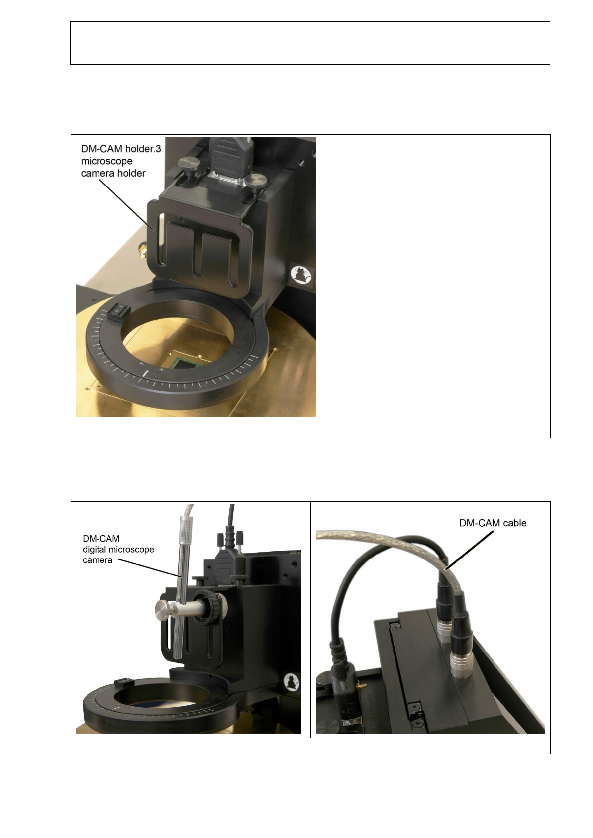
5.4 Installing the DM-CAM Digital Microscope Camera...................................................................9
5.5 Installing an ICR-Probe.............................................................................................................10
5.6 Installing a Passive Near-Field Probe......................................................................................13
5.7 Connecting a Measurement Device for Near-Field Scans using the Example of a Spectrum
Analyzer....................................................................................................................................16
5.8 Connecting a Computer............................................................................................................16
5.9 Connecting the Power Cable....................................................................................................17
5.10 Checking the Emergency Stop.................................................................................................17
6Software Installation................................................................................................ 18
6.1 Installing the Scanner Driver ....................................................................................................18
7Setting up and Commissioning.............................................................................. 21
8Operational Notes.................................................................................................... 23
8.1 Connecting the IC Scanner to your PC....................................................................................23
8.2 Placing a Probe at a Specific Distance above a Test IC .........................................................23
8.3 Determine the Duration of a Measurement with the IC Scanner.............................................24
8.3.1 Moving Distance.....................................................................................................................24
8.3.2 Sweep Time ...........................................................................................................................24
8.3.3 Transfer Time.........................................................................................................................24
9Warranty...................................................................................................................25

- 3 / 25 -
LANGER
EMV-Technik
DE-01728 Bannewitz
mail@langer-emv.de
www.langer-emv.com
ICS 105 IC Scanner set
1 Safety Instructions
Read and follow the operating instructions carefully and keep them in a safe place for later
consultation. The devices may only be used by personnel who are qualified in the field of
electromagnetic compatibility (EMC) and who are eligible to carry out this work.
When using a product from Langer EMV-Technik GmbH, please observe the following safety
instructions to protect yourself from electric shocks and the risk of injuries and to protect the
devices used and the test IC from destruction.
-Observe the operating and safety instructions for all devices used in the set-up.
-Never use any damaged or defective devices.
-Carry out a visual check before using a measurement set-up with a Langer
EMV-Technik GmbH product. Replace any damaged connecting cables before
starting the product.
-Never leave a product from Langer EMV-Technik GmbH unattended whilst this is in
operation.
-The Langer EMV-Technik GmbH product may only be used for its intended purpose.
Any other use is forbidden.
-Make sure the ICS 105 and accessories are connected to a properly grounded power
source.
-Do not connect or disconnect any cable while the ICS 105 is powered on.
-Do not drop or spill foreign objects or material such as screws or liquids onto the ICS
105.
-Do not touch any moving parts while the ICS 105 is running to avoid injury.
-Loading and unloading of parts and material must be done when the ICS 105 is not
running.
-Changing of fixtures or tooling must be done with the power source disconnected.
-The ICS 105 should only be operated in an environment of 0 to 40 degrees
centigrade and humidity of 20 to 95 percent with no condensation.
-Only use a neutral detergent for cleaning the ICS 105.

- 4 / 25 -
LANGER
EMV-Technik
DE-01728 Bannewitz
mail@langer-emv.de
www.langer-emv.com
ICS 105 IC Scanner set
2 Scope of Delivery
Item Designation Type Qty.
1 4-Axis Positioning System ICS 105 1
2 Ground Plane GND 25 1
3 ChipScan-Scanner Software CS-Scanner 1
4 Digital Microscope Camera DM-CAM 1
5 Accessories ICS 105 acc 1
6 User Manual ICS 105 m 1
-----------------------------------------------------------------------------------------------------------------------------------

- 5 / 25 -
LANGER
EMV-Technik
DE-01728 Bannewitz
mail@langer-emv.de
www.langer-emv.com
ICS 105 IC Scanner set
3 Technical Parameters
Supply voltage
110 / 230 V
Interface
USB
Max. traverse distance
(50 x 50 x 50) mm
α-Rotation ±180°
Min. positioning distance
(10 x 10 x 10) µm
α-Rotation 1°
Positioning speed
2 mm/s
α-Rotation 45°/s
Weight
23 kg
Sizes (L x W x H)
(350 x 400 x 420) mm
Table 1: General technical parameters of ICS 105
Axes
X
Y
Z
α-rotation
Max. measuring
range
50 mm
50 mm
50 mm
+/- 180°
Accuracy
10 µm
10 µm
10 µm
1°
Repeatability
+/- 1 µm
+/- 1 µm
+/- 1 µm
+/- 1°
Speed
2 mm/s
2 mm/s
2 mm/s
45°/s
Table 2: Technical parameters of the four axes of the ICS 105
Operating system
Windows 7 64-bit (latest service packs)
Monitor resolution
(1280 x 1024) px
HD space
1 GB
Periphery
CD-ROM drive for installation
Table 3: System requirements for computer
Processor
Intel Core i7 2.7 GHz
Memory
8 GB
Graphics card
AMD Radeon 7950
Graphics memory
3 GB
Table 4: Recommended specifications for using the software ChipScan-Scanner

- 6 / 25 -
LANGER
EMV-Technik
DE-01728 Bannewitz
mail@langer-emv.de
www.langer-emv.com
ICS 105 IC Scanner set
Diameter
218 mm
Depth of the recess
1.7 mm
Opening
(103 x 103) mm
Weight
2 kg
Height
24 mm
Table 5: Technical parameters of GND 25 ground plane

- 7 / 25 -
LANGER
EMV-Technik
DE-01728 Bannewitz
mail@langer-emv.de
www.langer-emv.com
ICS 105 IC Scanner set
4 Intended Use
The ICS 105 is a 4-axis positioning system. It uses probes of Langer EMV-Technik GmbH for IC
tests and measurements. Following Probes, among others, are supported:
- ICR near-field micro probes
- passive near-field probes
- and ICI L-EFT sources
Depending on the used probe type decoupled fields of the test IC can be measured or
interferences can be injected.
The probes can be moved across the X-, Y- and Z-axis and rotated along the Z-axis. The
distance between the test IC and the probe tip can be visually checked with the DM-CAM digital
microscope camera. The ICS 105 is controlled by the ChipScan-Scanner Software via
computer.
Fields of Application (a selection):
Surface scans over test ICs in accordance with IEC61967-3
Volume scans over test ICs
PIN scans
Side channel analysis / fault injection

- 8 / 25 -
LANGER
EMV-Technik
DE-01728 Bannewitz
mail@langer-emv.de
www.langer-emv.com
ICS 105 IC Scanner set
5 Measurement Set-up
5.1 Installing the GND 25 holder
The GND 25 holder (Figure 1a) is installed directly onto the XY stage. Insert the appropriate
screws to the four holes in the middle of the holder and secure them to the XY stage. Next, insert
the anti-rotation protection screw (Figure 1b), as needed, in one of the four outer holes of the
holder. This screw protects against an accidentally rotation of the GND 25 ground plane.
Figure 1: GND 25 holder
with anti-rotation protection screw
5.2 Installing the Groundplane GND 25
The GND 25 ground plane (Figure 2) is placed on the GND 25 holder so that the anti-rotation
protection screw fits into one of the notches on the bottom side of the ground plane. The GND 25
ground plane can be quickly rotated by 45° or 90°, as needed, by using a different notch.
Figure 2: GND 25 Groundplane

- 9 / 25 -
LANGER
EMV-Technik
DE-01728 Bannewitz
mail@langer-emv.de
www.langer-emv.com
ICS 105 IC Scanner set
5.3 Installing the DM-CAM holder.3 Camera Holder
Screw the DM-CAM holder.3 to the rotary unit with the black knurled screws.
Figure 3: Attached DM-CAM camera holder
5.4 Installing the DM-CAM Digital Microscope Camera
Screw the DM-CAM digital microscope camera into the DM-CAM holder.3 with the knurled screw.
Figure 4: Installed DM-CAM digital microscope camera
Connect the DM-CAM digital microscope camera cable to the ICS 105 IC scanner

- 10 / 25 -
LANGER
EMV-Technik
DE-01728 Bannewitz
mail@langer-emv.de
www.langer-emv.com
ICS 105 IC Scanner set
5.5 Installing an ICR-Probe
Important! Remove the protective cap of the ICR probe only after its installation because the probe
tip of the ICR probe is highly sensitive to mechanical stress. Re-attach it again after the
measurement has ended.
Screw the ICR probe to the rotary unit with the small knurled screws as shown in Figure 5. Next,
connect one ending of the SSMB-SSMB cable to the SSMB socket of the ICR probe (Figure 6) and
the other ending on the backside of the connector of the rotary unit (Figure 7).
The angular SMA connector of the SMA-SMA RA measurement cable is fixed to the SMA socket of
the ICR probe (Figure 8) and the other ending is subsequently fixed to the SMA socket
(measurement input) of the ICS 105 (Figure 9). Fix both cables to the rotary unit as shown in
Figure 10.
Figure 5: ICR probe attached to the rotary unit
Figure 6: Attached SSMB-SSMB cable for collision control

- 11 / 25 -
LANGER
EMV-Technik
DE-01728 Bannewitz
mail@langer-emv.de
www.langer-emv.com
ICS 105 IC Scanner set
Figure 7: SSMB-SSMB cable attached to the connector of the rotary unit
Figure 8: Attached SMA-SMA RA measurement cable

- 12 / 25 -
LANGER
EMV-Technik
DE-01728 Bannewitz
mail@langer-emv.de
www.langer-emv.com
ICS 105 IC Scanner set
Figure 9: SMA-SMA RA measurement cable attached to the ICS 105 IC scanner
Figure 10: The cables fixed on the rotary unit

- 13 / 25 -
LANGER
EMV-Technik
DE-01728 Bannewitz
mail@langer-emv.de
www.langer-emv.com
ICS 105 IC Scanner set
5.6 Installing a Passive Near-Field Probe
To use a near-field probe the SH 01 probe holder has to be installed first. Screw the SH 01 onto
the rotary unit with the help of the small knurled screws (Figure 11). Next, put the near-field probe
into the metal tube of the SH 01 and carefully tighten the screw by hand (Figure 12).
For easy installation of the near-field probe the magnetic metal tube can be taken off from the
probe holder. With the help of the notch in the metal tube it can be placed precisely in the SH 01
probe holder.
Depending on the measurement output of the used near-field probe attach a matching
measurement cable and subsequently connect it to the SMA socket (measurement input) of the
ICS 105 (Figure 13).
Connect one ending of the SSMB-SSMB cable to the SSMB socket of the SH 01 probe holder
(Figure 14) and the other ending on the backside of the connector of the rotary unit (Figure 15) to
enable the collision control function.
Figure 11: Attached SH 01 probe holder

- 14 / 25 -
LANGER
EMV-Technik
DE-01728 Bannewitz
mail@langer-emv.de
www.langer-emv.com
ICS 105 IC Scanner set
Figure 12: Near-field probe attached to the SH 01 probe holder
Figure 13: Attached measurement cable

- 15 / 25 -
LANGER
EMV-Technik
DE-01728 Bannewitz
mail@langer-emv.de
www.langer-emv.com
ICS 105 IC Scanner set
Figure 14: Attached SSMB-SSMB cable for collision control
Figure 15: SSMB cable for collision control attached to the connector of the rotary unit

- 16 / 25 -
LANGER
EMV-Technik
DE-01728 Bannewitz
mail@langer-emv.de
www.langer-emv.com
ICS 105 IC Scanner set
5.7 Connecting a Measurement Device for Near-Field Scans using the
Example of a Spectrum Analyzer
To connect a spectrum analyzer with a (micro) near-field probe, which is already connected to the
ICS 105 IC scanner, attach one ending of a matching measurement cable to the RF input of the
spectrum analyzer and the other ending to the SMA socket of the ICS 105 (Figure 16).
Depending on the probe type it may be necessary to switch an external power supply (BT 706 bias
tee) and/or an external preamplifier into the signal path.
A list containing all supported spectrum analyzers by ChipScan-Scanner software can be found in
the appendix of the ChipScan-Scanner user manual.
Figure 16: SMA connector for the measurement device
5.8 Connecting a Computer
To connect a computer to the ICS 105 IC scanner a USB type A to type B cable is used. Put the
USB type A connector into a USB port of the computer and put the USB type B connector into the
USB type B port of the ICS 105 (Figure 17).
Figure 17: USB type B port of ICS 105 IC scanner

- 17 / 25 -
LANGER
EMV-Technik
DE-01728 Bannewitz
mail@langer-emv.de
www.langer-emv.com
ICS 105 IC Scanner set
5.9 Connecting the Power Cable
Connect the 230 V power cable to the power supply of the ICS 105 IC scanner (Figure 18).
Figure 18: Power socket of the ICS 105 IC scanner
5.10 Checking the Emergency Stop
For transport purposes the emergency stop is active (pushed in) as a safety measure. As long as
the emergency stop button is pushed, the ICS 105 IC scanner cannot be operated.
Before starting the ICS 105 check if the emergency stop button is pushed, in that case, turn the red
button in the direction of the imprinted arrows (Figure 19).
Figure 19: Active emergency stop button (pushed)
and inactive emergency stop button

- 18 / 25 -
LANGER
EMV-Technik
DE-01728 Bannewitz
mail@langer-emv.de
www.langer-emv.com
ICS 105 IC Scanner set
6 Software Installation
Before the software installation the set-up of the entire system hardware needs to be completed
in accordance to chapter 5. To start the installation process of the ChipScan-Scanner software,
please insert the delivered installation CD-ROM into your CD-ROM drive.
Hints for installing the software ChipScan-Scanner can be found in the user manual of the
software with the file name ‘chipscan.pdf’ in chapter 1 in the folder ‘documentation’ on the CD-
ROM.
6.1 Installing the Scanner Driver
As the driver is not installed automatically by Windows when the IC scanner is connected to your
computer, the driver installation needs to be done manually.
1) Switch on the IC scanner and connect it to your computer via the provided USB cable.
2) Open the Windows Device Control from the Windows System control.
3) Within the Windows Device Control double click on the ‘Trinamic Stepper Device’ entry
within the ‘Other Devices’ tree item.
4) In the appearing properties dialog select the ‘Driver’ tab and click on ‘Update Driver’.
Figure 20: ‘Trinamik Stepper Device‘ (not installed yet) in Windows Device Control

- 19 / 25 -
LANGER
EMV-Technik
DE-01728 Bannewitz
mail@langer-emv.de
www.langer-emv.com
ICS 105 IC Scanner set
Figure 21: Select ‘Update Driver‘ in the properties window of ‘Trinamic Stepper Device’
5) In the following dialog choose the option to manually search for the driver in your computer.
Figure 22: Manually search for the driver
6) Use the browse button, select the CD-ROM drive where you inserted the
ChipScan-Scanner installation CD-ROM, select the Driver subdirectory from the CD-ROM
and press the Continue button.

- 20 / 25 -
LANGER
EMV-Technik
DE-01728 Bannewitz
mail@langer-emv.de
www.langer-emv.com
ICS 105 IC Scanner set
Figure 23: Browse the computer to find the CD-ROM drive with the driver
7. The driver is installed and it should appear in the Windows Device Manager as follows.
Figure 24: Installed ‘Trinamic Stepper Device‘
Table of contents
Popular Laboratory Equipment manuals by other brands

Omni
Omni PCR-258 user manual

Nippon Genetics Europe
Nippon Genetics Europe FastGene PG01 manual

Pfeuffer
Pfeuffer Sample cleaner MLN operating instructions

THORLABS
THORLABS Vytran FFS2000 Series user guide

Scientific Industries
Scientific Industries Vortex-Genie 2 Series operating instructions

IKA
IKA C 1.30 operating instructions