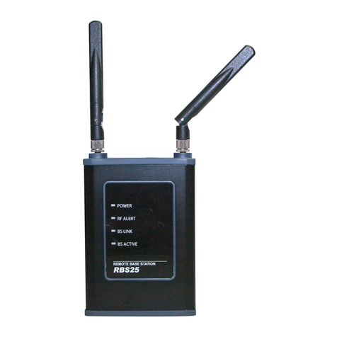
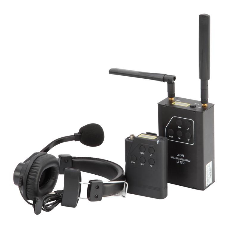
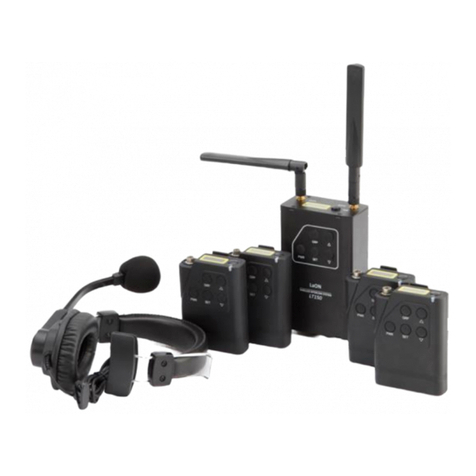
LAON TECHNOLOGY LT750 Series User manual

ⓒ2017 LAON Technology Co., Ltd. All rights reserved.
LaON LT750 EXPERT SYSTEM with RBS75 QUICK REFERENCE
(Ver.1.3_1 NOVEMBER 2017)
1) SYSTEM AT A GLANCE and HOW TO SUPPLY THE POWER
1-1)BS (Base Station)
[Figure 1-1] Front panel of the Base Station, LTWI-BS750
[Figure 1-2] Rear panel of the Base Station
1
2
3
4
5
6
7
8
9
10
17
14
15
16
12
1
3
5
2
4
6
7
8
10
9
11
13
LT750
1. BS Headset TALK button with indicator light
2. BS communication group selection
3. 4-Wire on/off button with indicator light
4. 4-Wire communication group selection
5. AUX IN, AUX IN/OUT on/off with indicator light
6. AUX IN, AUX IN/OUT comm. group selection
7. RF ALERT indicator light
8. Remote Base Station LINK Indicator light
9. Remote Base Station ACTIVE indicator light
10. Headset speaker volume control (UP)/ Menu selection
11. Headset speaker volume control (DOWN)/ Menu Selection
12. Menu selection (LEFT)
13. Menu selection (RIGHT)
14. Menu SET button
15. Headset cable connector
16. Hands free/PTT mode selection
17. OLED menu display
1. Antenna connector
2. AUX IN connector
3. AUX OUT connector
4. 4-Wire connector
5. Power switch
6. Antenna connector
7. 8-OHM speaker 2-pin spring clamp connector
8. USB connector
9. LAN RJ-45 connector
10. Power connector

ⓒ2017 LAON Technology Co., Ltd. All rights reserved.
[Figure 1-3] Rear panel of the 19”cascade kit, ‘BSCCK100’
aAC100-240V power in for PoE HUB which is built in the kit
b100-240VAC power adapter for BS
c PoE Port 1, 2, 3
d Antenna connectors (RX, TX)
e Auxiliary In
f Auxiliary Out
g Phone jack for 8Ω Speaker output (1W into 8Ω)
h4-Wire In
I4-Wire out
※NOTE
‘Power toggle switch’is on the rear panel of the Base station BS750 or on the front panel of the 19”
cascade kit.
If you install the Base Station ‘without’the cascade kit;
Connect the power cord to the power connector on the rear panel of the Base Station BS750 and turn
on the power toggle switch on the rear panel of the BS.
If you install the Base Station ‘with’the cascade kit;
Connect the power cord to the power connector on the rear panel of the cascade kit and turn on the
power toggle switch on the front panel of the cascade kit.
Then the BS screen on the front panel of the BS will be displayed. Wait for one(1) minute until the RF
channel is scanned automatically for the Base Station.

ⓒ2017 LAON Technology Co., Ltd. All rights reserved.
1-2)BP (Belt pack)
※QUICK NOTE
Key operation for BP pairing: PWR(hold) + SET
Key operation for manual hands off between stations: PWR + PWR (double click of ‘PWR’)
Key operation for key lock: PWR(hold) + GRP
There are three ways to supply power to BP as following;
LaON provided rechargeable NiMH battery, LTWI-BAT50
AA type alkaline battery (x 2ea)
Non-LaON provided rechargeable battery
Press the power button(‘PWR’) on the front of the BP longer than 2 seconds after the battery is
equipped. Do the same to turn off the BP.
※CAUTION
While you do not use the system long, store the battery after charged and separate from the Belt Pack.
Turn off the Belt Pack when charging.
Use the high quality AA type alkaline battery if applicable.
[Figure 1-4] Belt Pack front and rear controls
9
10
11
1
4
2
7
3
5
6
8
1. Headset cable connector
2. OLED display
3. BP TALK button with indicator light,
TALK button for former group in
‘TWO GROUPS’mode
4. Power (PWR) button
5. Communication group selection (GRP),
TALK button for latter group in
‘TWO GROUPS’mode
6. Speaker volume control (UP) /
Menu selection button
7. Menu SET button
8. Headset speaker volume control (DOWN)/
Menu selection button
9. Belt clipper
10. Battery cover
11. Charger terminals (bottom)

ⓒ2017 LAON Technology Co., Ltd. All rights reserved.
1-3)RBS (Remote Base Station)
There are two ways to supply power to RBS as following;
Power of Ethernet(PoE) Hub –recommended most
LaON provided power adapter
Upon the power supply to the RBS, it will be turned on automatically without pressing the power button.
6
5
7
1
2
4
3
8
9
[Figure 1-5] Remote Base Station
1. Antenna connector
2. Antenna connector
3. Null (Power button)
4. Status lights
5. 12V DC power connector
6. USB connector
7. LAN RJ-45 connector
8. Cover

ⓒ2017 LAON Technology Co., Ltd. All rights reserved.
2) DISPLAY MENU CONTROL
2-1) Base Station display menu
※NOTE & CAUTION
Press SET button for 2 seconds on any menu screens will lead you to the NORMAL menu.
Menu displays will be in sleep mode if no touch is made for approximately 30 minutes.
Touching any button on the front panel of the Base Station will have the screen waken up.
RESET Menu, SELECT RF CH Menu and TX ON OFF SET Menu are basically not to be used by
users frequently. Please make an enough caution to use these menus.
If pressing HF/PTT key while the BS menu appears, the hidden menu, TX ON/OFF SET will pop
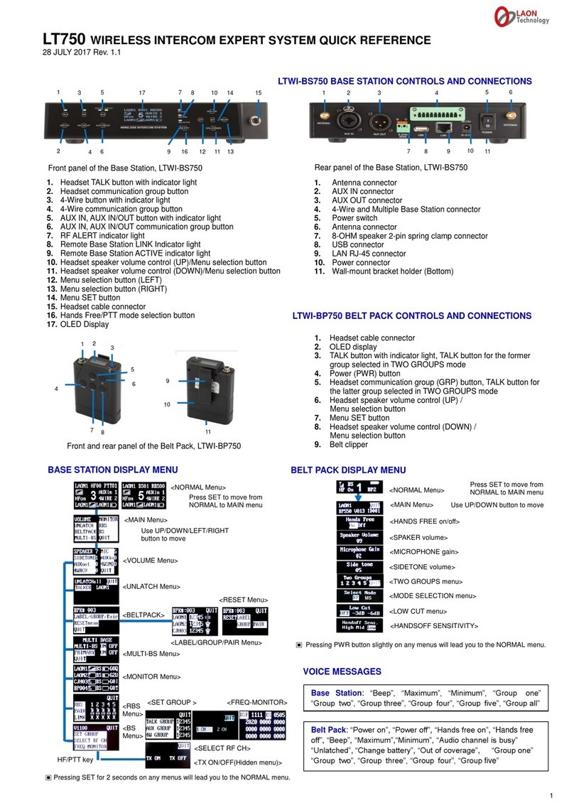
<BS Menu>
<MULTI-BS Menu>
<MAIN Menu> - Various subjects for respective setup will be shown here.
Use UP/DOWN/LEFT/RIGHT direction keys to move and press SET to set.
<VOLUME Menu>
<UNLATCH Menu>
<RBS Menu>
RBS pairing
can be made
here.
<BELTPACK Menu>
<NORMAL Menu> - initial screen
Press SET to move from NORMAL menu to MAIN menu.
<MONITOR
Menu>
<LABEL/GROUP/PAIR Menu> - BP pairing setup can
be made here.
<RESET Menu> - Caution needed to use!
This will delete all settings
previously made.
<TX ON/OFF SET Menu>
Caution needed to use!
When ‘no signal’from the BS is needed,
set to ‘TX OFF’.
<SET GROUP Menu>
<FREQ-MONITOR menu >
HF/PTT Key

ⓒ2017 LAON Technology Co., Ltd. All rights reserved.
up. When there is too wide overlapping area observed between the BS and RBS, and if no BP is
needed to link up to the BS but RBS, you may select TX OFF to totally turn off the BS signal. If
you want to return to TX ON mode after using the system in TX OFF mode for a while, you
should reboot the system with the toggle power switch on the BS. And make sure the BS is in
TX ON mode when you implement the BP pairing/registration process.
2-2) Belt pack display menu
※NOTE
Press PWR button on any menu displays of the BP will make you return to the NORMAL menu.
If no touch is made the screen will be in sleep mode. Press any button to make it waken up.
From the NORMAL Menu, you can monitor the applicable RSSI signal, the linked device,
battery status, hands free on/off status, group number selected and BP ID(Label).
<MAIN Menu>
Use UP/DOWN direction keys to move to the next menus.
<Hands Free On/Off>
<Speaker Volume>
<Microphone Gain>
<Side tone volume>
<Two Groups> If you select two groups here, you can listen both groups
at the same time and talk to either one group. To talk to former group
selected, press ‘TALK’button and to latter group, ‘GRP’button.
<Hands off Sensitivity>
If BS and RBS/RBSs are located nearby each other and there are wide
overlapping areas, and for that reason if the smooth automatic handoff is
not made (with audio breakups) though the BP user has moved to other
RBS area, set the level to ‘High’for sensitive and agile handoff.
<NORMAL Menu>
Press SET to move from NORMAL Menu(initial screen) to MAIN menu.
BP750
MS
<Mode Selection> By selecting the mode to MS(Master Station), the
applicable BP will play a role as a master where there is no BS in the area.
By changing the mode, BP will automatically be rebooted for RF scan.
After done, ‘MS’will be indicated on the NORMAL menu instead of BP ID.
<Low Cut> To cut the low frequency at maximum, select -6db.
<Speaker Volume in Two Groups set mode>

ⓒ2017 LAON Technology Co., Ltd. All rights reserved.
3) PAIR UP/REGISTER THE SYSTEM
3-1) Pair up BP with BS
Before initially using, all BPs to be in use should be registered to an applicable BS with information setup
as required. Once the pairing is done, BPs will automatically be linked to all RBSs in each area, of which
are registered to the applicable BS as well.
Connect the antennas enclosed firmly to the BS and turn the power on.
From the initial screen of the BS, press SET button then it will lead you to the menu screen as shown
from the figure 3 below. Move to BELTPACK menu and press SET button on it.
[Figure 2] NORMAL menu (Initial screen of BS) [Figure 3] MAIN menu (Menu selection for setup)
Set the maximum number of BP on the first row in the BELTPACK menu display by using UP and DOWN
direction key as shown from the figure 4 below. For an instance, if 40 BPs to be registered, input ‘040’.
Any BP exceed this number set initially in this screen will not be registered. Move into
LABEL/GROUP/PAIR menu then the display as shown from the figure 5 will appear and you will see the
maximum number of BP you have just set from the first row.
‘BP Lable’‘Group #’‘Pairing status indication icon’
[Figure 4] BELTPCK menu [Figure 5] LABEL/GROUP/PAIR menu
Pairing status indication icon
(): Factory default status with no input of paring data
(): Data edited and being ready to execute paring
(): Paring processing
(): Paring failed
( ): Paring completed –communication is available from this stage.
Move to the ‘BP Label(ID) column’in the second row with LEFT/RIGHT keys and set the ID as you want
by using UP/DOWN keys. Press SET to save and move to ‘Group # column’and select group or groups
for the applicable BP by pressing SET button onto each number. Move onto the icon and stay.

ⓒ2017 LAON Technology Co., Ltd. All rights reserved.
Turn on the BP near the BS antenna. For all BPs which are not registered yet will go on red LED blinking.
Go back to the BS screen. Press SET on the icon then it will try to start pairing with the BP by changing
the icon to .
On BP, confirm if the OLED screen is on and NORMAL menu is displayed. While pressing and holding the
PWR button, quickly press the SET button and release both after confirming the message ‘Pairing….’on
the BP screen. ‘Pairing completed’message will be shown shortly if properly done. The pairing status
indication icon on the BS screen will be changed to and the BP ID you have input for the applicable
BP will be displayed on the BP screen. If the pairing is failed, ‘Pairing failed’will be shown on the BP
screen and the icon will be indicated on the BS screen. If failed, try again in the correct order and
timing.
In the same way above, execute the pairing for all BPs one by one on each row. Going down on the
screen with direction key will show you the next rows.
※NOTE & CAUTION
Do not press the BP PWR button longer than 2 seconds that will make the power turned off.
The BS screen will be in a sleep mode if no touch is made for a while. Touch any button on the
BS will make the screen waken up.
The BP screen will be in a sleep mode if no pressing is made for a while. Pressing any button on
the BP will make the screen waken up. When set up the pairing, the initial screen should be on.
On BS screen, press SET in 2 seconds on any menu will take you to the initial NORMAL menu.
3-2) Pair up RBS with BS
Before initially using, BS and RBS or RBSs should be paired up. The pairing set up can be done for
one(1) RBS at once. Therefore, connect the LAN cable with the applicable one(1) RBS only and
disconnect all other cables for the rest of RBSs. For this pairing, prepare a short LAN cable to connect
between BS and the applicable RBS will be enough.
Connect the LAN cable between BS and the applicable RBS by using LAN port. If you have 19”cascade
kit, there are 3 LAN(PoE) ports on the rear panel of the kit and you may wish to use any of them for
this pairing setup. For the power supply to the RBS, PoE Hub or batteries can be used.
※NOTE
After the BS is booted with the initial screen shown up, wait approx 4 minutes to start the RBS pairing.
Once the power is supplied and LAN cable is connected to the BS and RBS properly, from the initial
screen of the BS, press SET button on the BS then it will lead you to the menu screen as shown from the
figure 7 below. Move to RBS menu and press SET button on it then the RBS menu will be displayed as
shown from below figure 8.
[Figure 6] NORMAL menu (Initial display of BS) [Figure 7] MAIN menu (menu selection)
[Figure 8] RBS menu
RBS #
Pairing status indication icon
Link status indication

ⓒ2017 LAON Technology Co., Ltd. All rights reserved.
: Press ‘RIGHT’ direction key from the QUIT position on the display will lead you to the RBS #6 to 10(A).
: ‘A’stands for ‘10th RBS’(RBS 10)
Implement the RBS pairing from the number ‘1’ on the display in order.Move onto ‘1’ with direction
key and press SET then the pairing will start by changing the pairing icon indication from to . If
the pairing is successfully completed, the icon will be changed to and it may take a bit time until
the LINK indication on the bottom line of the display will be changed from ‘X’ to ‘O’. You may observe
the change of LINK indication after getting out from the current display with QUIT button and return to
the display again. When failed, the pairing icon will be returned to the initial indication. If failed,
confirm the power supply, LAN cable suitability and LINK LED status on both BS and RBS then try again.
LED status lights on the front panel of the BS and RBS
‘RF ALERT light’
When there are audio breakups seriously, RF ALERT light will go on.
‘BS LINK light / RBS LINK light’
When the BS and RBS are connected, BS LINK/RBS LINK light will go on.
‘BS ACTIVE light / RBS ACTIVE light’
When the BS/RBS exchanges data, BS ACTIVE/RBS ACTIVE light will be flashing.
Disconnect the LAN cable for the first RBS(R1) if the pairing is properly done, then, connect the next
RBS for pairing. Again, for the pairing, RBS should be connected one by one exclusively and have to be
located in order from #1, the nearest area from the BS, to #10(‘A’), the farthest area from the BS.
Implement the pairing one by one for each RBS with the same process above.
If you want to test the RBS coverage at this stage, while all the RBSs are placed at each area with
cabling, reboot the BS with the power toggle switch while the RBSs are TURNED ON, then wait for
one(1) minute for the RF scan of BS and then 20 seconds for each RBS until the system is fully
activated.
With above pairing setup and system reboot, each BP within the RBS coverage will be linked to the
respective RBS and the wireless intercom communication will be activated. You may wish to test the
BP communications and RBS coverage. As shown from the figure 9 below, BP users will be able to
confirm to which device the BP is linked from the first row of the BP display as well as the signal
strength, battery status, group number selected, BP ID and etc. If the BP is linked to BS within the BS
coverage, the display indicates ‘BS’and if ‘RBS’, ‘R1’‘R2’‘R3’… ‘Ra’.
‘Device linked’‘Group #’‘Device linked’(‘Ra’= ‘R10’)
[Figure 9] NORMAL menu (Initial screen of the BP)
And, when there are data exchanges by communications, the ‘RBS ACTIVE’ LED light of the BS and ‘BS
ACTIVE’LED light of the RBS will go on.
※NOTE & CAUTION
During the BS and RBS pairing process, communication will be inactivated.
Do not try BP or RBS pairing while the automatic RF scanning is implemented upon
booting/rebooting the system.
When users changed any setting by accident, there could possibly a disconnection of the
pairing between the BS and RBS unintentionally. If you have any issue on communication,
firstly check out the power supply with PoE Hub, specification/length of the LAN cable in use,
LAN cable connection status and then RF LINK and ALERT light indications. And implement
the pairing setup again to retrieve.
ⓒ2017 LAON Technology Co., Ltd. All rights reserved.
4) LOCATE the BS and RBS/RBSs
Before you fix out the BS and RBSs’locations, consider the best spots for each of them at the
installation site. If BS and RBS will be located on each individual floor level, or where there is a concrete
wall between the spaces and totally isolated not allowing any gap, you may not needed to consider the
overlapping area between the BS and RBS. If the BS and RBS will be co-located in one open space where
there is no obstruction, or located closer though there are obstructions, you may wish to test and check
out the coverage and overlapping area in each BS and RBS area and install them at the best locations as
higher as possible not allowing wide overlapping area.
Please note that the RF signal range can be various and alternative depending on the site environment
such as the location of obstructions, materials of the walls, doors, windows and ceiling, and the system
installation height and location, and other equipments used in the site and etc. Please note that the
typical distance of LaON intercom is approximately 100m-140m for both of BS and RBS in LOS (line of
sight) environment however it could be increased due to reflection or decreased due to obstruc
tions as well. Therefore, test and checking out each of coverage by BS and RBSs and select the best loca
tion is very important for the efficient cabling and the best-in-class wireless communications
performance.
[Figure 10] Mapping coverage zones
Draw the coverage map and deploy the BS and RBS in order from the RBS1(R1) in the nearest area from
the BS, and RBS2(R2) in the next nearest area from the BS……and RBS10(Ra) in the farthest area from
the BS as shown from the figure 10.
5) CABLING and CONNECTION BETWEEN BS and RBSs
For multiple RBSs connections, it is necessary to connect through PoE(Power of Ethernet) Hub. For one(1)
RBS connection, either direct connection or connection via PoE Hub should work. However, it is still
strongly recommended to use a PoE Hub if you prefer a convenient power supply to the RBS during the
critical live operations.
Connect the BS and RBSs through LAN cable. The LAN port can be found from the rear panel of the BS or
19” cascade kit and bottom of the RBS.
Zone B
RBS1
Coverage Area
Zone C
RBS2
Coverage Area
Zone A
BS
Coverage Area
Zone D
RBS3
Coverage Area

ⓒ2017 LAON Technology Co., Ltd. All rights reserved.
[Figure 11] LAN ports of BS and RBS
If the cable length is exceeded 80m, STP cable is strongly recommended to use for a stable network
environment.
Cable length ≤ 80M: Connect with CAT-5 STANDARD LAN Cable
80M ≤ Cable length ≥ 100M: Connect with CAT-5e STP LAN Cable
Cable length ≥ 100M: Connect with Optical Fiber Cable with Converter
To cover wide communication area, RBS can be added and connected through PoE Hub as required as
shown from the figure 12 below. Also, to make the cable length longer, you can put additional PoE Hubs
at appropriate locations as shown from the system configuration example below. For the cable length of
each section between the BS and PoE hub, between the PoE Hub and RBS, and between the PoE Hubs see
the guideline above, the same.
When the BS and RBS are properly connected, The BS LINK LED light on the front panel of the RBS and
the RBS LINK LED light on the front panel of the BS will go on in green.
[Figure 12] System usage example

ⓒ2017 LAON Technology Co., Ltd. All rights reserved.
6) SYSTEM BOOTING and AUTOMATIC RF CHANNEL SCANNING
Once all the pairing set up, RBS deployment and cabling is done, you need to boot/reboot the system
and wait until the automatic RF channel scanning is completed.
There are two ways to boot the system correctly in order.
A. Turn on the all RBSs(by PoE Hub) first →Turn on the BS after the RBSs →Wait for one(1)
minute until the BS completes the RF scanning →Wait for 20 seconds by each RBS until they
complete the RF scanning
B. Turn on the all BS and RBS after all cable connections →Reboot the BS only with the toggle
power switch on the BS or on the 19”cascade kit if used (this will mean, ‘turn on the all RBS
first and then BS’, the same procedure with above ‘A’) →Wait for one(1) minute until the BS
completes the RF scanning →Wait for 20 seconds by each RBS until they complete the RF
scanning
※NOTE
For an instance, time needed for booting and RF auto-scanning in case of ‘1 BS with 7 RBS’ will
approximately be ‘3 minute and 20 seconds+’. During this time, do not try to pair up the BP or
RBS.
If any RBS is not turned on before the BS, the applicable RBS will not properly receive the
signal for RF scanning from BS, and could occupy the duplicated RF channel which is used by
other BS or RBS and this may cause a RF conflict. Thus, BS rebooting after any change on RBS
setup is critical.
The Power LED of RBS which is under scanning process goes on RED, and the wireless
communication will only be available after all the RF scanning process is completed.
The RF channels for each BS/RBSs will be automatically scanned and taken by upon above system
booting or rebooting.
[Figure 13] RF channel scanning matrix

ⓒ2017 LAON Technology Co., Ltd. All rights reserved.
On 5GHz, there are approximately 15 RF channels worldwide. If 1 BS with 8 RBSs are needed to install,
the BS will firstly scan and occupy the best RF channel and then, RBS1(R1) will secondly scan and occupy
the next best available channel, then RBS 2→3→4→5→6→7 and 8 in order.
Occupying a RF channel not so closed with the ones already taken by other BS/RBSs is feasible for the
pleasant wireless communication quality. Given this, for example, if BS has taken the RF channel #3 as
above figure 13, the next device, RBS1 will take a channel leaving some gaps from ch#3 not taking the
neighboring channels of it. In that way, as the multiple RBSs are taking good channels available, there
will finally be only neighboring channels left to take, of which case of RBS7 & 8 in the figure. Thus, if all
the 8 RBSs are located in the narrow same space, there could be interferences between RBS7(ch#9) and
RBS2(ch#10), and between RBS8(ch#2) and BS(ch#3) or RBS5(ch#1) as shown from the figure.
However, if they are located far from each other not allowing overlapping areas, it is no matter to use
the neighboring RF channels without conflicts or interferences and THAT IS WHY, the RBS deployment
‘IN ORDER’from the RBS1 in the nearest area from the BS, to the RBS10 in the farthest area from the BS
is highly recommended. Please note that RBS deployment in order, as paired up, from the nearest area
from the BS, without mess up, will deliver a pleasant wireless communication experiences.
※NOTE
The BS antennas can be disconnected with termination caps if the BS signal needs to weaken
and all BPs will be linked to RBSs depending on the site environment, conditions of installation
and the required wireless communication operation.
Or you can totally off the TX signal of the BS with a touch screen menu on the front panel of the
BS. See the NOTE in 2-1) Base Station display menu above.
The BS and RBS antenna direction can be adjustable. To weaken the BS signal, lay down the two
antennas. Refer to the antenna direction guideline attached to this manual.
7) HAND OFF BETWEEN COVERAGE
When BP users move across the coverage, the applicable BP will be automatically linked to the BS or
RBS within the located area. When the automatic roaming is done, user can confirm the change from
the display of the BP as shown from the Figure 9 above. If the site environment or installation condition
doesn’t allow an automatic roaming due to wide overlapping area between coverage, manual hand off
is also available. Approach to the BS or RBS where you want to make the link and double click the power
button on the BP then, expect a beep sound with an instant red LED indication upon the new link to the
BS or RBS. Confirm the linked device indication in the BP display once you have tried the manual hand
off. Please take a caution to not press the power button longer than 2 seconds during this button
operation which will make the BP turned off.
Also, you can adjust the handoff Sensitivity level from ‘high’to ‘low’with a HANDOFF SENSITIVITY menu
on the BP for more sensitive and agile handoff operation between areas especially you are located in
the non-ideal installation environments.
8) MAIN FEATURES of LT750 EXPERT SYSTEM
LICENSE-FREE 5GHz UNII BAND
5GHz UNII Band, the worldwide license-free frequency band provides approximately up to 29
RF channels depending on the regions as opposed three (3) RF channels on 2.4GHz ISM band.
Therefore, users are able to enjoy pleasant wireless communications with even less traffics or
interferences. Due to high frequency band, the system is also hardly affected by high-power

ⓒ2017 LAON Technology Co., Ltd. All rights reserved.
digital equipments such as amplifiers and speakers.
SUPER-SCALABLE IP BASED REPEATER SOLUTION, REMOTE STATION
Remote Station(‘RBS’) supports to dramatically expand the wireless communication coverage.
Multiple studio spaces or multi-floors can be easily consolidated by adding Remote Station at
each space using the standard LAN network configuration. Up to ten (10) Remote Station can
be connected per Base Station, BS750 and it provides PoE (Power of Ethernet) function for the
convenient power supply. Automatic roaming is available between the Base Station and
Remote Stations.
INDUSTRY-TOP LEVEL AUDIO QUALITY
23ms low latency level and non-compressed audio transmission technology guarantee a high
quality audio performance. LT750 system is perfectly tuned professional wireless intercom
system that fits to use at various loud and congested site environments.
FIVE(5) COMMUNICATION GROUP CHANNEL
Single or multiple communication group channels can be assigned to the Base Station, Belt
Pack, 4-Wire and AUX devices each and those group channels can be used in single, multiple or
all together at the same time. With this flexible grouping capability, one (1) Base Station
covers IFB communication as well as IC and ISO communications without an additional IFB
system which is ‘more with less’ cost efficient solution.
ELEVEN(11) FULL-DUPLEX LISTEN & TALK COMMUNICATION CHANNEL (1 BS + 10 BPs)
Eleven (11) full-duplex audio channels are offered with one (1) Base Station. By making the full
use of this with multiple group channels, a number of independent teams are practically able
to have IFB and wireless communications in one (1) system respectively.
UP TO ONE HUNDRED AND TWENTY EIGHT(128) BELT PACK CONNECTION
One hundred and twenty eight (128) Belt Packs can be registered into a Base Station.
BELTPACK IN MASTER MODE
A Belt Pack can play a role as a master where there is no Base Station or the Base Station is
located far from the actual Belt Pack operation area.
4-WIRE AND AUXILIARY I/O INTERFACES
4-Wire and Auxiliary Input / Output ports are provided to secure seamless connections with
wired intercom systems, external audio devices and etc.
COMPACT DESIGN
Comfortable headset and compact Belt Pack with internal antenna support high wearability
with mobility even at the tough broadcasting or event sites.
VARIOUS OPTIONS ON BATTERY
Either LaON provided rechargeable battery or AA type Alkaline battery with LaON provided
designated battery sled can be used for supplying power to the Belt Pack. Also, non-LaON
provided rechargeable battery can be used with the battery sled.
MONITORING FUNCTIONS
LT750 system provides various monitoring functions for Base Station, Remote Station and Belt
Pack such as the link status, RSSI(Received Signal Strength Indication), battery status and
microphone gain level and etc.
MONITORING OF AUDIO BREAK-UP
When a Belt Pack is out of coverage, the Belt Pack user is easily able to monitor the audio
break-up with his/her side tone unlike other traditional wireless intercom systems.
TOP SECURITY WITH AES 256BIT LEVEL 3 ENCRYPTION
AES 256bit Level 3, the top level encryption technology is applied to secure confidential
communications.
EFFICIENT 7 PORT CHARGER
There are five (5) bays for charging the Belt Pack batteries which are equipped in the Belt
Packs and two (2) bays for charging the Belt Pack batteries which are separated from the Belt
Packs. Two (2) of them are for dual use for charging Remote Station or Mobile Station’s
batteries.

ⓒ2017 LAON Technology Co., Ltd. All rights reserved.
LaON IN-HOUSE TECHNOLOGIES AND SOLUTIONS
LaON has developed from the wireless SoC built in the systems to the wireless intercom
systems in-company by applying its own patent base technologies. Base on the know-how and
comprehensive experiences in wireless technology, LaON offers timely and prompt service
with full flexibilities for customer satisfactions with top priority.
9) TROUBLESHOOTING
When you have an issue on connecting between BS and RBS;
Confirm if the LAN cable you are using is appropriate –specification and cable length and etc.
Check out if the cable or connectors are broken.
Check out if the PoE Hub is in good condition without a fault.
Reboot the system and confirm if the LINK LED indications on both BS and RBS are correct.
Doubt if the pairing setup is cancelled by accident. Implement the pairing setup again
between the BS and RBS/RBSs and try again.
When connecting multiple RBSs, process the pairing one by one from the RBS number 1 to
10. The RBS which is already paired up should be disconnected and the RBS to be paired up
should exclusively be connected and turned on. In order to confirm to which the BP in use is
linked, see the BS monitor menu or BP display. It will display the linked device such as BS, R1,
R2…and Ra(R10). BS reboot is necessary after all are connected and turned on. Upon any
change on RBS setup, please do not miss out to reboot the BS.
During the scanning process of the BS and RBS/RBSs after booting or rebooting, audio
communication will be inactivated.
Do not try any pairing for BP or RBS during this time which may cause the RF channel
duplication.
If the system will be installed on the existing network, please refer to the section, ‘Remote
Base Station Setup’of LT550 Expert system manual or ask for a support to distributor or
manufacturer. Please note that configuring an exclusive dedicated network for LaON
intercom system is still strongly recommended to secure a stable network communication
environment.
When you have an issue on BP;
If the BP pairing setup does not work or the BP is not linked to the BS, confirm if the BS
antenna is firmly connected or if there is a defect on antenna parts. And confirm if the TX ON
is set in the BS menu properly.
If the BP does not link to the RBS, confirm the LAN cable connection, BS antenna and RBS LINK
light.
Please note that when a BP is under pairing process, the whole system communication will be
blocked with red LED flashing.
If audio break-up occurs, confirm if your BP is linked to the BS or RBS in your area. If not, set
the HANDOFF SENSITIVITY level to ‘High’in the menu of the BP and approach to the nearest
BS or RBS in your location, and double click the PWR button for a manual handoff to the BS or
RBS with the strongest signal in the area. Confirm if the BP is now linked to the nearest BS or
RBS after the manual handoff. This may happen due to the wide overlapping area and when
the signal from the BS or RBS in other areas is still strong.
If the battery status is low with red LED on, the TX of BP will automatically be off. If the BP
user still talks though, it may cause audio break-up to the whole communication network.
Change the battery immediately when the battery status is low.

ⓒ2017 LAON Technology Co., Ltd. All rights reserved.
When there is unknown issue such as interference, audio break-up, drop out and etc.
Reboot the system with BS toggle power switch then wait until all the rescan is completed
and try again.
If the issue is still not solved out though above actions, please contact the distributer in your
Other manuals for LT750 Series
1
This manual suits for next models
1
Table of contents
Other LAON TECHNOLOGY Intercom System manuals

LAON TECHNOLOGY
LAON TECHNOLOGY LT150 MOBILE User manual

LAON TECHNOLOGY
LAON TECHNOLOGY LT150 MOBILE User manual

LAON TECHNOLOGY
LAON TECHNOLOGY LT550 EXPERT SYSTEM RBS25 User manual

LAON TECHNOLOGY
LAON TECHNOLOGY LT150 MOBILE User manual

LAON TECHNOLOGY
LAON TECHNOLOGY LT250 User manual

LAON TECHNOLOGY
LAON TECHNOLOGY LT250 User manual

LAON TECHNOLOGY
LAON TECHNOLOGY LT750 Series User manual

LAON TECHNOLOGY
LAON TECHNOLOGY LT550 EXPERT User manual

LAON TECHNOLOGY
LAON TECHNOLOGY LT550 EXPERT User manual