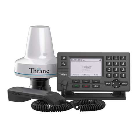
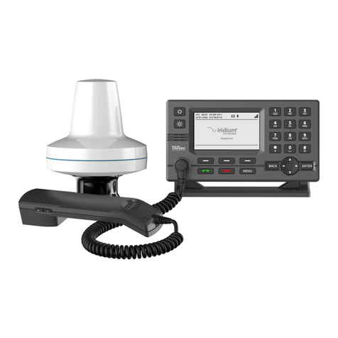
Lars Thrane Iridium Certus 200 Guide

User & Installation Manual
LT-4200 Satellite Communications System
Iridium Certus® 200
Document Number: 95-102665 Rev. 1.00
Release date: February, 2023
Copyright © Lars Thrane A/S
Denmark
ALL RIGHTS RESERVED


LT-4200 User & Installation Manual Rev. 1.00 Introduction
Lars Thrane A/S www.thrane.eu i
This Document is of © copyright to Lars Thrane A/S. It contains proprietary information, which is
disclosed for information purposes only. The contents of this document shall not in whole or in part be
used for any other purpose without prior permission from Lars Thrane A/S.
Disclaimer
Any responsibility or liability for loss or damage in connection with the use of this product and the
accompanying documentation is disclaimed by Lars Thrane A/S. The information in this manual is provided
for information purposes only, is subject to change without notice, and may contain ws or inaccuracies.
Manuals issued by Lars Thrane A/S are periodically revised and updated. Anyone relying on this information
should acquire the most current version e.g. from Lars Thrane A/S. Lars Thrane A/S is not responsible for
the content or accuracy of any translations or reproductions, in whole or in part, of this manual from any
other source.
Copyright
© 2023 Lars Thrane A/S. All rights reserved.
Disposal
Old electrical and electronic equipment marked with this symbol can contain substances hazardous to
human beings and the environment. Never dispose these items together with unsorted municipal waste
(household waste). In order to protect the environment and ensure the correct recycling of old equipment
as well as the re-utilization of individual components, use either public collection or private collection by
the local distributor of old electrical and electronic equipment marked with this symbol. Contact the local
distributor or dealer for information about what type of return system to use.
IMO and SOLAS
The equipment described in this manual is intended for use on commercial marine and leisure vessels. The
equipment is not covered by the International Maritime Organization (IMO) and Safety of Life at Sea
(SOLAS) regulations.

LT-4200 User & Installation Manual Rev. 1.00 Introduction
Lars Thrane A/S www.thrane.eu ii
WARNING - Product installation
To ensure correct performance of this equipment,
it is strongly recommended that professionals with
expertise, properly trained, and likewise authorized
within the industry is completing the installation.
Safety Instructions for Installer & Operator
The following safety instructions must be observed during all phases of operation, installation, service and
repair of this equipment. Failure to comply with these precautions or with specific warnings elsewhere in
this manual violates safety standards of design, manufacture and intended use of the equipment.
Lars Thrane A/S assumes no liability for the customer's failure to comply with these requirements.
Instructions for the Installer
Instructions for the Operator
WARNING –Do not disassemble
Do not disassemble or modify this equipment. Fire,
electrical shock, or serious injury can result.
WARNING –Keep away from live circuits
Operational personnel must not remove product
enclosure. Do not service the equipment with the
communication cable connected. Always
disconnect and discharge unit, cable and circuits
before touching them.
WARNING –Turn off power switch
Turn off the main power switch before installing
the equipment described in this manual. Do not
connect or disconnect equipment when the main
power switch is on.
WARNING –Use only the supplied cable
Use only the supplied power and communication
cable for connecting the equipment.
WARNING - Permanent watch
In case of smoke or water leaks into the
equipment, immediately turn off the power.
Continued use of the equipment can cause fire or
electrical shock. Keep access and permanent watch
of the equipment in order to prevent any
unwanted escalation.
WARNING –Input Power
The input voltage is: 24 VDC.
WARNING –Power supply protection
Make sure that the power supply is adequately
protected by a fuse or an automatic circuit breaker
when installing the equipment (15.0 A).
WARNING - Explosive atmosphere
Do not operate the equipment in the presence of
flammable gases or fumes. Operation of any
electrical equipment in such an environment
constitutes a definite hazard.
WARNING - Compass safe distance
The compass safe distance for standard and
steering compasses is 1.40 m (4.6 ft) and 0.90 m
(3.0 ft) respectively. Observe these distances to
prevent interference to a magnetic compass.
IMPORTANT - Safety distance
The safety distance from the LT-4230 Antenna
Unit, when the LT-4230 Antenna Unit is powered
and transmitting, is 0.4 m (1.3 ft), in order to
comply with the regional regulations.
Always keep this safety distance to the LT-4230
Antenna Unit to avoid any serious injury.
If the safety precautions and warnings on this site are not followed, warranty will be void.
WARNING –DC mains connector
The DC mains connector is to be used as the
disconnection device to isolate the equipment
from the mains supply.

LT-4200 User & Installation Manual Rev. 1.00 Introduction
Lars Thrane A/S www.thrane.eu iii
Required information for the reader
Throughout this document, essential information will be presented to the reader. The following text
(emphasized) has the following meaning and/or implication:
WARNING: A ‘Warning’ is an Operation or Service procedure that, if not avoided, may cause a hazard
situation, which could result in personnel death or serious injury.
IMPORTANT: Text marked ‘Important’ provides essential information to the reader and is key information
to the user for the equipment to work properly. Damage to the equipment can occur if
instructions are not followed.
NOTE: A ‘Note’ provides essential information to the reader.
IMPORTANT –FCC Compliance Note:
This equipment has been tested and found to comply with the limits for a Class B digital device, pursuant to
part 15 of the FCC Rules. These limits are designed to provide reasonable protection against harmful
interference in a residential installation. This equipment generates, uses and can radiate radio frequency
energy and, if not installed and used in accordance with the instructions, may cause harmful interference to
radio communications. However, there is no guarantee that interference will not occur in a particular
installation. If this equipment does cause harmful interference to radio or television reception, which can be
determined by turning the equipment off and on, the user is encouraged to try to correct the interference
by one of the following measures:
- Reorient or relocate the receiving antenna.
- Increase the separation between the equipment and the receiver.
- Connect the equipment into an outlet on a circuit different from that to which the receiver is connected.
- Consult the dealer or an experienced radio/TV technician for help.
This product does not contain any user-serviceable parts.
Repairs should only be made by an authorized Lars Thrane A/S service center. Unauthorized repairs or
modifications could result in permanent damage to the equipment and void your warranty and your
authority to operate this device under Part 15 regulations.
IMPORTANT –Innovation, Science and Economic Development Canada Compliance Note:
This device complies with Innovation, Science and Economic Development Canada license-exempt RSS
standard(s). Operation is subject to the following two conditions: (1) this device may not cause interference,
and (2) this device must accept any interference, including interference that may cause undesired operation
of the device.

LT-4200 User & Installation Manual Rev. 1.00 Introduction
Lars Thrane A/S www.thrane.eu iv
About this manual
Intended readers
This is a User & Installation Manual for LT-4200 Satellite Communications System, or LT-4200 system. The
manual is primarily intended for installers and service personnel.
Personnel installing or servicing the system should be professionals with technical expertise, properly
trained, and likewise authorized.
All safety instructions and guidelines in this manual must be observed. The safety instructions are listed in
the beginning of the manual. The guidelines are to be found in the separate chapters, where it is needed.

LT-4200 User & Installation Manual Rev. 1.00 Introduction
Lars Thrane A/S www.thrane.eu v
Software versions
This manual is applicable to the following software:
IMPORTANT: The latest software released by Lars Thrane A/S must always be used for new installations
of the LT-4200 System. The LT-4200 system should always be up to date to ensure the best
possible performance of the system and services.
NOTE: The latest LT-4200 Software and Release Notes can always be downloaded from the Lars
Thrane A/S website. Please contact Lars Thrane A/S for details about future software
releases and features.
Software Versions
Description
P/N
Version
LT-4200 System
71-102662
1.00R
Table 1: Software Versions

LT-4200 User & Installation Manual Rev. 1.00 Introduction
Lars Thrane A/S www.thrane.eu vi
Record of Revisions
Rev.
Description
Release Date
Initials
1.00
Initial Release
February, 2023
KTL

LT-4200 User & Installation Manual Rev. 1.00 Introduction
Lars Thrane A/S www.thrane.eu vii
Table of Contents
Introduction ...................................................................................................................................................... 1
Application and Limitations.............................................................................................................................. 2
Unpacking (in-the-box)..................................................................................................................................... 3
Inspection...................................................................................................................................................... 3
Accessories........................................................................................................................................................ 4
Mounts .......................................................................................................................................................... 4
Cable and connectors ................................................................................................................................... 4
System Overview .............................................................................................................................................. 5
Installation and Mounting................................................................................................................................ 6
LT-4210 Control Unit..................................................................................................................................... 6
LT-3120 Handset ........................................................................................................................................... 9
LT-3121 Cradle............................................................................................................................................. 10
LT-4230 Antenna Unit................................................................................................................................. 11
Pole Mount (2.0” pipe, Ø53.0mm, A4 Stainless), Antenna Unit............................................................... 19
Interfaces......................................................................................................................................................... 22
LT-4210 Control Unit................................................................................................................................... 22
LT-4230 Antenna Unit................................................................................................................................. 30
Power Consumption ....................................................................................................................................... 32
Maximum.................................................................................................................................................... 32
DC Isolation Resistance and Chassis Ground ................................................................................................. 33
Galvanic Isolated Power Supply..................................................................................................................... 35
AC/DC Galvanic Isolated Power Supply ..................................................................................................... 35
DC/DC Galvanic Isolated Power Supply ..................................................................................................... 35
User Interface (UI)........................................................................................................................................... 36
Display......................................................................................................................................................... 37
Menu System .............................................................................................................................................. 41
Activating the System..................................................................................................................................... 43
Acquire a Certus SIM Card.......................................................................................................................... 43
Postpaid Voice Features ............................................................................................................................. 43
Who’s My Service Provider ........................................................................................................................ 44
Change of Hardware and Software................................................................................................................ 45
Change of Hardware................................................................................................................................... 45
Software Update......................................................................................................................................... 46

LT-4200 User & Installation Manual Rev. 1.00 Introduction
Lars Thrane A/S www.thrane.eu viii
System Services............................................................................................................................................... 47
Voice Call..................................................................................................................................................... 47
Data ............................................................................................................................................................. 52
System Submenus........................................................................................................................................... 57
Phone .......................................................................................................................................................... 57
Settings........................................................................................................................................................ 60
System......................................................................................................................................................... 66
Bridge Alert Management (BAM)................................................................................................................... 71
Serial Interface (RS-422) ................................................................................................................................. 75
GNSS sentences........................................................................................................................................... 75
BAM sentences ........................................................................................................................................... 76
NMEA 0183 over UDP..................................................................................................................................... 77
Web server...................................................................................................................................................... 78
Accessing the built-in web server............................................................................................................... 79
Dashboard................................................................................................................................................... 80
Configuration .............................................................................................................................................. 81
Maintenance ............................................................................................................................................. 104
Legal notice ............................................................................................................................................... 107
Log out....................................................................................................................................................... 107
Disable login timeout................................................................................................................................ 107
Service & Repair............................................................................................................................................ 108
Appendixes.................................................................................................................................................... 109
App. A Applicable Standards .................................................................................................................... 109
App. B Bridge Alert Management (BAM)................................................................................................. 110
App. C Multiple talkers and multiple listeners ........................................................................................ 112
App. D GNSS sentences............................................................................................................................. 113
App. E BAM Sentences.............................................................................................................................. 114
App. F GNSS Receiver Integrity States ..................................................................................................... 115
App. G - Specifications.............................................................................................................................. 120
App. H - Outline Drawing: LT-4210 Control Unit...................................................................................... 121
App. I - Outline Drawing: Bracket Mount, Control Unit .......................................................................... 122
App. J - Outline Drawing: Flush Mount, Control Unit.............................................................................. 123
App. K - Outline Drawing: LT-4230 Antenna Unit.................................................................................... 124
App. L - Outline Drawing: Pole Mount (2.0” pipe, 53.0mm, A4 Stainless), Antenna Unit ..................... 126

LT-4200 User & Installation Manual Rev. 1.00 Introduction
Lars Thrane A/S www.thrane.eu ix
App. M - Outline Drawing: LT-3120 Handset........................................................................................... 127
App. N - Outline Drawing: LT-3121 Cradle ............................................................................................... 128

LT-4200 User & Installation Manual Rev. 1.00 Introduction
Lars Thrane A/S www.thrane.eu Page 1 of 128
Introduction
Congratulations on your purchase of the LT-4200 Satellite Communications system - Iridium Certus® 200!
The LT-4200 Satellite Communications System is a maritime satellite communication product from Lars
Thrane A/S. The LT-4200 system is designed for the professional market (deep sea, fishing, and workboats),
but can be used for the leisure market as well. The LT-4200 system meets all standards and certification
requirements needed for worldwide maritime satellite communication equipment.
The LT-4200 system has voice and data capabilities with 100% global coverage provided by the Iridium®
Communications Network. The LT-4200 system offers the following Iridium services:
•3 x Voice Channels (high quality)
•IP-data: Up to 176 kbps (up) / 176 kbps (down)
The LT-4200 system consists of a control unit, antenna unit, handset, and cradle.
A single coaxial cable connects the control unit with the antenna unit. Using a standard coaxial cable, up to
150 meters of separation between the units can be obtained, giving freedom to mount the antenna unit in
the best possible location, with free line of sight to the Iridium satellites.
The LT-4200 system can be used as the primary satellite communication product on vessels, covering the
basic communication needs in terms of connectivity between the ship and shore and ship to ship.

LT-4200 User & Installation Manual Rev. 1.00 Application and Limitations
Lars Thrane A/S www.thrane.eu Page 2 of 128
Application and Limitations
•The LT-4200 system shall be installed according to manufacturer’s User & Installation Manual.
•The LT-4200 system includes an integrated Global Navigation Satellite System (GNSS) receiver for
position fixing.
•The LT-4230 Antenna Unit operational low temperature is: -40°C (-40°F)

LT-4200 User & Installation Manual Rev. 1.00 Unpacking (in-the-box)
Lars Thrane A/S www.thrane.eu Page 3 of 128
Unpacking (in-the-box)
Unpack the LT-4200 Satellite Communications System - Basic (P/N: 90-102608) and check that the following
items are present in the box:
•51-102664 LT-4210 Control Unit
•51-100988 LT-3120 Handset
•51-101181 LT-3121 Cradle
•51-102640 LT-4230 Antenna Unit
•91-100771 Bracket Mount, Control Unit
•91-102118 Power Cable, 3m
•4 x Stainless steel A4 screws (for Bracket Mount, Control Unit)
•2 x Stainless steel A4 screws (for Cradle)
•4 x Unit Test Sheets
•95-102665 LT-4200 User & Installation Manual
NOTE: The Antenna unit mount (pole mount) is not included in the LT-4200 Satellite
Communications System - Basic (P/N: 90-102656) and must be ordered separately. The
antenna unit must only be mounted, using the pole mount, delivered by Lars Thrane A/S.
The antenna unit mounts are listed with part numbers (P/N) in Accessories on page 4.
Inspection
Inspect the shipping cartons and/or wooden box immediately upon receipt for evidence of damage during
transport. If the shipping material is severely damaged or water stained, request that the carrier's agent is
present when opening the cartons and/or wooden box. Save all box packing material for future use.
After unpacking the system and opening the cartons, inspect it thoroughly for hidden damage and loose
components or fittings. If the contents are incomplete, if there is mechanical damage or defect, or if the
system does not work properly, notify your distributor.
WARNING: To avoid electric shock, do not apply power to the LT-4200 system components if there is
any sign of shipping damage to any part of a unit or the outer cover. Read the Safety
Instructions at the front of this manual before installing or operating the system.

LT-4200 User & Installation Manual Rev. 1.00 Accessories
Lars Thrane A/S www.thrane.eu Page 4 of 128
Accessories
Mounts
The following accessory parts are not part of the basic system and must be ordered separately:
•91-100772 Flush Mount, Control Unit
•91-102967 Pole Mount (2.0” pipe, Ø53.0mm, A4 Stainless), Antenna Unit
Cable and connectors
The following cable and connector parts are not part of the basic system and must be ordered separately:
•91-100768 Aux Cable, 3m
•91-101137 Coaxial Cable Ø10.3mm 10m
•91-101138 Coaxial Cable Ø10.3mm 25m
•91-101139 Coaxial Cable Ø10.3mm 50m
•91-101186 N Conn. (male) for Coaxial Cable Ø10.3mm
•91-101188 Crimping Tool for Coaxial Cable Ø10.3mm
Coaxial cables are delivered with one fixed N connector (outdoor mounting), another loose N connector
and crimp parts comes with the cable. It is required to use an appropriate crimping tool for attaching the
loose N connector.
NOTE: For further details on the cable and connectors, please contact Lars Thrane A/S. When
using a 24 VDC power source, a coaxial cable up to a length of 150 meters can be used for
connecting the LT-4210 Control Unit and the LT-4230 Antenna Unit. Details about the
coaxial cable, specification, and cable lengths, are described in LT-4230 Antenna Unit on
page 11.

LT-4200 User & Installation Manual Rev. 1.00 System Overview
Lars Thrane A/S www.thrane.eu Page 5 of 128
System Overview
The LT-4200 Satellite Communications System is a standalone communication product, which is using the
Iridium® satellite constellation. The LT-4200 system is working on the Iridium® NEXT satellites. An overview
of the LT-4200 system is illustrated in Figure 1.
The LT-4200 system consists of the following units, provided by Lars Thrane A/S:
•LT-4210 Control Unit
•LT-3120 Handset
•LT-3121 Cradle
•LT-4230 Antenna Unit
Figure 1: LT-4200 system - basic components and interfaces.

LT-4200 User & Installation Manual Rev. 1.00 Installation and Mounting
Lars Thrane A/S www.thrane.eu Page 6 of 128
Installation and Mounting
LT-4210 Control Unit
The LT-4210 Control Unit is the master unit in the system, supporting all external interfaces and the
operational user interface. The LT-4210 Control Unit is designed for indoor mounting. Check the
specifications in App. G - Specifications on page 120.
The LT-4210 Control Unit has the following interfaces:
•4-pin power connector (male), marked ‘PWR’
•Chassis ground connector, marked ‘GNDC’
•N connector (female) for coaxial cable to the LT-4230 Antenna Unit, marked ‘ANT’
•Ethernet (RJ-45) connector, marked ‘LAN’
•10-pin auxiliary connector (male), marked ‘AUX’
•SIM card, marked ‘SIM’
•5-pin connector (female) for LT-3120 Handset (front of the control unit)
The interfaces on the back side of the LT-4210 Control Unit are illustrated in Figure 3 on page 7.
Figure 2: LT-4210 Control Unit (front view).

LT-4200 User & Installation Manual Rev. 1.00 Installation and Mounting
Lars Thrane A/S www.thrane.eu Page 7 of 128
The LT-4210 Control Unit interfaces are described in Interfaces on page 22. The LT-4210 Control Unit, front
and backside view, are illustrated in Figure 2 and Figure 3.
The LT-4210 Control Unit user interface, display and buttons, are described in User Interface (UI) on page
36.
NOTE: The LT-4210 Control Unit must be mounted with either the Bracket Mount, Control Unit
(P/N: 91-100771) or Flush Mount, Control Unit (P/N: 91-100772) - illustrated in Figure 4
and Figure 5. The Flush Mount, Control Unit is not included in the LT-4200 Satellite
Communications System - Basic (P/N: 90-102656)and must be ordered separately.
Mounting and installation considerations:
For optimum system performance, the following guidelines on where to install and mount the LT-4210
Control Unit must be followed. It is recommended to mount the unit in a location which fulfills these
requirements:
•Mount the unit indoor (not exposed to direct water)
•Mount the unit using either the bracket mount or flush mount
•Mount the unit on a rigid structure with a minimum of exposure to vibration and shock
•Mount the unit in an area with an ambient temperature between -15°C to +55°C (+5°F to +131°F)
Figure 3: LT-4210 Control Unit (backside view).

LT-4200 User & Installation Manual Rev. 1.00 Installation and Mounting
Lars Thrane A/S www.thrane.eu Page 9 of 128
LT-3120 Handset
The LT-3120 Handset is the primary voice interface for the LT-4200 system. The LT-3120 Handset must be
connected to the front of the LT-4210 Control Unit. The connector is illustrated in Figure 2 on page 6.
The LT-3120 Handset is connected to the LT-4210 Control Unit via a 5-pin proprietary angle connector. The
spiral cord, fixed to the LT-3120 Handset is ~ 0.4 m from handset to connector, when coiled. The spiral cord
can be stretched to a maximum of 2 m. The LT-3120 Handset is designed for indoor mounting. Check the
specifications in App. G - Specifications on page 120.
The LT-3120 Handset has the following characteristics:
•High-performance audio speaker and microphone
•Separate ringer (buzzer)
•Speaker volume control (double-button, marked with ‘+’ and ‘-‘, for volume up and down)
•Built-in off-hook detection circuit
NOTE: The LT-4210 Control Unit will inform the user if the LT-3120 handset is not properly
connected to the LT-4210 Control Unit. A BAM alert will be activated (Lost handset).
NOTE: The LT-3120 Handset must be operated together with the LT-3121 Cradle, for the off-hook
detection circuit to work. The LT-3121 Cradle is described in LT-3121 Cradle on page 10.
Figure 6: LT-3120 Handset (front view).
Figure 7: LT-3121 Handset (back view).
This manual suits for next models
1
Table of contents
Other Lars Thrane Conference System manuals
Popular Conference System manuals by other brands

Cisco
Cisco EX90 user guide

Thrane&Thrane
Thrane&Thrane EXPLORER 110 quick start

Barco
Barco ClickShare CX-20 set Gen 2 installation manual

Pentair Pool Products
Pentair Pool Products Pool and Spa IntelliComm Installation and user guide

Polycom
Polycom SoundPoint IP 500CS user guide

Middle Atlantic Products
Middle Atlantic Products VTC Series instruction sheet