Lasermet ICS-6 User manual

ICS-6 Instruction Manual
01000-53-000 Issue 11 19 January 2021
LASERMET ICS-6
INSTRUCTION MANUAL
FAIL SAFE LASER
INTERLOCK CONTROL SYSTEM

ICS-6 Instruction Manual
01000-53-000 Page 2 of 42 Issue 11 19 January 2021
LASERMET ICS-6
Instruction Manual
Contents
1 Declaration of Conformity ......................................................................................................4
2 Concept ..................................................................................................................................5
2.1 Safety Warnings .............................................................................................................7
2.1.1 Symbols .......................................................................................................................7
3 Summary of Evaluation of Compliance to EN ISO 13849-1:2015 ..........................................8
4 Installation ..............................................................................................................................9
5 Wiring ...................................................................................................................................10
5.1 Mains In ........................................................................................................................10
5.1.1 ICS-6 (110V to 240V ac 50-60Hz) ..............................................................................10
5.1.2 ICS-6-24 (24VDC) ......................................................................................................11
5.2 ICS-6 Inputs ..................................................................................................................11
5.2.1 Mechanical Interlock Switches .................................................................................11
5.2.2 Coded Magnetic Interlock Switches .........................................................................14
5.2.3 Emergency Stop and Break Glass Switches ..............................................................14
5.2.4 Master Control and Connection to Fire Alarm .........................................................15
5.3 ICS-6 Illuminated Sign Control Output .........................................................................16
5.3.1 Low Voltage DC Warning Signs .................................................................................16
5.4 Interlock Operator Output Contacts ............................................................................18
5.4.1 Laser Power Supply ...................................................................................................18
5.4.2 Beam Shutters ..........................................................................................................19
5.4.3 Interlock Connectors ................................................................................................22
5.4.4 Electro Magnetic Door Locks ....................................................................................23
5.5 Override ........................................................................................................................25
5.5.1 Override / Entry Keypad ...........................................................................................25
5.5.2 Override Switch with Timer ......................................................................................26

ICS-6 Instruction Manual
01000-53-000 Page 3 of 42 Issue 11 19 January 2021
5.5.3 Override Switch without Timer ................................................................................27
5.5.4 Local Override ...........................................................................................................27
5.5.5 Override Alarm .........................................................................................................28
5.6 Typical Installation .......................................................................................................28
6 Expansion Boards .................................................................................................................30
6.1 Introduction..................................................................................................................30
6.2 Installing Expansion Boards ..........................................................................................31
7 Mismatch Detector ..............................................................................................................33
7.1 Description ...................................................................................................................33
7.2 Configurable Options for Safety Circuit Mismatch Events ...........................................33
7.3 Clearing a Mismatch Fault Indication ...........................................................................34
7.4 Remote Test and Reset ................................................................................................35
8 LED Indicators .......................................................................................................................36
9 Operation .............................................................................................................................38
9.1 Starting Up....................................................................................................................38
9.2 Resuming Operation after an Interlock Switch has been opened ...............................38
9.3 Using the Override .......................................................................................................39
10 Specifications ...................................................................................................................40
11 Warranty ..........................................................................................................................41
12 Contact Details .................................................................................................................42

ICS-6 Instruction Manual
01000-53-000 Page 4 of 42 Issue 11 19 January 2021
1 Declaration of Conformity
LASERMET LIMITED
INTERLOCK CONTROL PANEL ICS-6
Drawing Number 01000-00-000
DECLARATION OF CONFORMITY
This is to certify that the ICS-6 Interlock Control Panel designated by Lasermet Drawing
Number 01000-00-000 has been tested in accordance with the following directives and
standards and found to comply.
Lasermet certifies that this product complies with the basic requirements for health
and safety as provided by the following directives and standards:
Directives: Machinery Directive 2006/42/EC June 2010
Low Voltage Directive 2014/35/EU
EMC Directive 2014/30/EU
Standards: EN ISO 13849-1:2015
Safety of Machinery: Safety-related parts of Control Systems
EN 60947-1:2007 +A1:2010 +A2:2014
Low Voltage Switchgear and Control
EN 61010-1:2010 +A1:2016 +A2: 2019
Safety Requirements for Electrical Equipment
Supplier:
Lasermet Limited
Lasermet House
137 Hankinson Road
Bournemouth
BH9 1HR
Dorset
United Kingdom
Country of Origin: England
Date: 3 November 2019

ICS-6 Instruction Manual
01000-53-000 Page 5 of 42 Issue 11 19 January 2021
2 Concept
The ICS-6 provides control of an interlock system primarily intended to protect persons from
accidental exposure to hazardous lasers. It is able to monitor several doors, windows, curtains etc.
fitted with safety interlock switches and disable the laser if any are open. In this manual the term
‘Door Switch’ refers to any interlock switch which may be fitted to a door, cover, window blind etc.
The versatile ICS-6 system can be connected to any number of door switches and can indicate the
status of up to 4 switches or groups of switches.
An Arm Laser button is provided to arm the laser when all the safety requirements are met. A key
lock prevents unauthorised use of the system.
The ICS-6 has a fully dual channel cross-checked architecture and when correctly wired can realise a
system compliant with EN ISO 13849-1 up to performance level ‘e’.
Three safety interlock outputs each rated at 6A resistive, 250Vac, are provided to enable the laser,
operate door locks etc. The interlock outputs are volt-free contacts which close when the system is
armed. Each contact actually comprises two contacts in series. In the event of one contact failing to
open, the other contact will open and the system is then disabled, preventing further use and
maintaining safety. The contacts can be configured for a variety of options.
The ICS-6 is available in enhanced versions which offer the following options:
Nine Interlock Output contacts, seven rated at 8A, 50VDC maximum and two rated at 8A,
250Vac.
Three-pole safety power contactors which may be used to switch single or three-phase laser
mains supplies.
A separate changeover contact is provided for operating one or two-way illuminated warning signs.
The ICS-6 is able to monitor output devices such as contactors and shutters with feedback (such as
Lasermet’s LS-20 beam shutter) and the signs will display a danger indication in the event of a
monitored output device failing or partly failing to assume the safe state when the system is
disarmed.
A remote master switch or master interlock system may be connected such that one or more ICS-6’s
can be controlled by one central point. The master system can prevent the ICS-6 and its associated
laser from being armed. The ICS-6 can be linked to a fire alarm so that the laser is disarmed, and any
controlled doors are unlocked in the event of an alarm.
Other features include emergency stop control with indication, and provision for an entry/exit timed
override option with pushbutton or coded keypad entry. The system may be interconnected with
site access control systems.

ICS-6 Instruction Manual
01000-53-000 Page 6 of 42 Issue 11 19 January 2021
The ICS-6 has a mismatch detector which when wired to a full dual-channel system disables the
system in the event of a mismatch between the two safety circuits. This provides protection against
the failure of a door switch etc.
The ICS-6 can accommodate expansion modules internally, and Lasermet have a range of modules
either available or in development including:
Uncommitted Relays
Active Beamguard
Safety Logic Plus
Network Interface
Lasermet provides a full range of equipment including interlock switches, illuminated warning signs,
laser shutters, entry keypads with built-in fail-safe override timer, door locks, external power
supplies etc. which can be connected to the ICS-6 to provide a complete system. Full support, design
and installation is available from Lasermet, please contact us for any queries. Contact details are
given at the end of this manual.

ICS-6 Instruction Manual
01000-53-000 Page 7 of 42 Issue 11 19 January 2021
2.1 Safety Warnings
This device is intended to be used as part of a safety system which may be used to protect personnel
and equipment from possible injury, damage, or loss.
As such it must be installed and wired according to these instructions and tested by suitably
qualified persons. No attempt may be made to tamper with the parts, open them, or use them
outside of the parameters contained herein.
The units are only designed to be fixed to surfaces using their inbuilt fixing holes. They must not
come into contact with each other or any other moving part when in use. The parts should never be
subject to impact or mechanical strain.
Safety switches should never be defeated or bypassed. It is imperative that all steps are taken to
ensure that any spare actuators are made unavailable, such that they cannot be used to defeat the
switch or reduce the protection offered by the system in any way.
If the equipment is used in a manner not specified by Lasermet, the protection provided by the
equipment may be impaired.
Lasermet reserves the right to change the design, modify the operation of functions or add new
features at any time without prior notice.
2.1.1 Symbols
Shock Hazard
Protective Earth

ICS-6 Instruction Manual
01000-53-000 Page 8 of 42 Issue 11 19 January 2021
3 Summary of Evaluation of Compliance to EN ISO 13849-1:2015
Note that this summary relates to the ICS-6 controller only. To achieve a complete system
performance level ‘e’ the system must be wired as described in this manual using suitably rated door
sensors and measures taken to minimise the effects of common cause failures in the sensors and
wiring which may be connected to the unit.
Required Characteristics:
Architecture Category 3/4
Performance Level Required (PLr) PLr = e
Application Demand Base:
In service operation 365 days/year
Functional demand on the controller once per hour
Achieved Characteristics:
Architecture Category 4
Performance Level (PL) PL = e
PFH [1/h] 2.47xE-8
MTTFd 100 years
Mission Time 20 years

ICS-6 Instruction Manual
01000-53-000 Page 9 of 42 Issue 11 19 January 2021
4 Installation
The ICS-6 is designed to be permanently attached to a wall or other fixed vertical surface.
The ICS-6 should be mounted in a convenient position for use and wiring. During use it will be
necessary for operators to access the controls and to observe the indications.
For rooms where personnel may work inside while the laser is operating this is often near the main
entry door, but it can be near the working position within the room if preferred. For enclosures
which personnel leave before activating the laser, the ICS-6 may be fitted on the outside of the
enclosure itself or somewhere convenient nearby.
During installation, wired connections will need to be made from the ICS-6 to all the interlocked
doors, warning signs, laser interlocks, shutters and other equipment as required by the system, and
allowance should be made for the installation of electrical conduits, trunking etc. to make entry to
the unit.
There should be adequate clearance beneath the unit to allow the front door to be fully opened
downwards. Installation will be impaired if the door cannot be fully opened. Care should be taken
that any conduit or trunking beneath the unit will allow the door to open sufficiently.
To open the unit, unlock the catch by turning the lock with a flat screwdriver until the slot is
horizontal. Press the release bar downwards and the cover will unlock. It can then be hinged
downwards and will snap into the upright position.
Four Ø5mm fixing holes are provided in the four corners of the case for mounting purposes.
The cables for mains supply, door switches, laser control etc. are usually fed to the unit through
plastic trunking or 22mm diameter plastic conduit, and holes are required to be made in the case to
accommodate the entry points. An electrician’s conduit hole cutter is the ideal tool for this purpose.
The conduit may be surface mounted or buried in the wall and should be arranged to ensure that
holes can be made in the enclosure in the required positions. If surface-mounted conduit is used the
top and bottom faces of the case will usually be found to provide the most convenient entry points.
All connections are made on the narrow circuit board located in the bottom of the case. All of the
terminals are identified on the circuit board.
The connection circuit board may be temporarily removed during installation. With the exception of
the 9-way Interlock option in the shallow case, the board can also be refitted in any of three
different locations in the case to suit the cable entry points.
Care should be taken in the running of conduits that the proposed entry position in the ICS-6 can be
accommodated and that the front cover of the ICS-6 can be opened.

ICS-6 Instruction Manual
01000-53-000 Page 10 of 42 Issue 11 19 January 2021
5 Wiring
Warning. This unit operates from mains electricity. There is mains voltage on the circuit boards and
some of the terminals. Always disconnect the mains power supply before opening the unit or
attempting any wiring alterations.
The ICS-6 is a versatile interlock system and there are a variety of ways in which it can be used. Be
sure you know which configuration you require before you attempt to wire the unit. If you require
further assistance, please call Lasermet technical help. Contact details are at the end of this manual.
All connections are made to plug-in terminals on the narrow circuit board located in the bottom half
of the case. It is usually easiest to unplug the terminals while the connections are being made. A
2.5mm slotted screwdriver will be needed to access the smaller terminals.
5.1 Mains In
5.1.1 ICS-6 (110V to 240V ac 50-60Hz)
The ICS-6 has a universal mains voltage input and does not need setting for different supply
voltages.
It is recommended that a circuit breaker or other external switch is provided for the mains supply to
the unit depending on the amount of additional equipment connected to the ICS-6. This should be
mounted in a suitable location which can be easily reached. We recommend that a switched fused
spur (fused between 3A and 8A) with neon indicator is provided. In all cases the supply must be
protected by an overcurrent device not exceeding 8A.
Wire the incoming mains power to the following terminals on the narrow circuit board in the
bottom of the case:
Live - L IN
Neutral - N IN
Protective Earth - PE
Note. The protective earthing cable connection is required.
Note. Only terminals J11 and J12 (IO1 and IO2 respectively) on the ICS Interlock Board are for
primary voltage.

ICS-6 Instruction Manual
01000-53-000 Page 11 of 42 Issue 11 19 January 2021
5.1.2 ICS-6-24 (24VDC)
Using the ICS-6-24 I/O board, the ICS-6 can be configured to operate at 24VDC.
Wire the 24V power supply to the following terminals on the ICS-6-24 I/O board.
Power supply must be at least 100W. Lasermet provides an appropriate 24V power supply. Contact
details given at the end of this manual.
5.2 ICS-6 Inputs
5.2.1 Mechanical Interlock Switches
Up to four door interlock switches may be directly wired to the ICS-6. By making external
connections, more switches can be added and arranged in groups for indication purposes.
The interlock switches are wired to the terminals labelled INTERLOCK 1 through to INTERLOCK 4.
Each interlock switch should have two safety contacts which are closed when the door is closed.
Some door contacts such as Lasermet’s IS-MECH switches have an additional monitor contact which
closes when the door is opened. This is not used in ICS-6.
A 4-way terminal block is provided for each door interlock switch. One of the safety contacts which
are closed when the door is closed is wired to the ‘A’ terminals. The other safety contact is wired to
the ‘B’ terminals.
If the system is required to perform to ISO 13849 performance level ‘e’, two switches are usually
required to be fitted to each door, with the safety contact of one switch wired to the ‘A’ terminals
and the safety contact from the second switch wired in a separate cable to the ‘B’ terminals. If there
is any possibility of both cables being damaged for the same reason simultaneously it may also be
necessary to route the cables in different paths.

ICS-6 Instruction Manual
01000-53-000 Page 12 of 42 Issue 11 19 January 2021
If the laser hazard is considered low, it is possible to use switches with only one safety contact. In
this case connect the switch across the ‘A’ terminals. Fit a wire link across the ‘B’ terminals. The
Mismatch Detector cannot be used and must be disabled, see the Mismatch Detector section below.
It is usual to use low voltage 4-core flexible cable for these connections and Lasermet can supply
suitable cable in standard PVC or low smoke zero halogen (LSZH) types.
If an Interlock input is not used, one wire link should be fitted to connect the ‘A’ terminals together,
and a second wire link to connect the ‘B’ terminals on each unused terminal block.
The example diagram below shows a system with two doors wired for ISO 13849 performance level
‘e’. Each door has two switches.
A
B
B
A
INTERLOCK
1
INTERLOCK
2
INTERLOCK
3
INTERLOCK
4
Door
Interlock
Switch 1A
Wire
Links
Wire
Links
NOTE:
Door Interlock Switches
shown with door closed.
Door
Interlock
Switch 1B
Door 1
Door
Interlock
Switch 2A
Door
Interlock
Switch 2B
Door 2
A
B
B
A
A
B
B
A
A
B
B
A
If you have more than four doors you can wire them in groups. A common situation is where there
are double doors. Interlock switches need to be fitted to both, and the two doors can then be wired
together so that a single monitor indication light will illuminate on the front panel of the ICS-6 if
either of the doors is open. The switches in a group should be wired with their safety contacts in
series. Each group may have several switches. An example diagram for two door interlock switches
wired in a group is shown below.

ICS-6 Instruction Manual
01000-53-000 Page 13 of 42 Issue 11 19 January 2021
A
B
B
A
INTERLOCK
1
Door
Interlock
Switch 1A
Door
Interlock
Switch 1B
Door 1
Door
Interlock
Switch 2A
Door
Interlock
Switch 2B
Door 2
NOTE:
Door Interlock
Switches
shown with door
closed.
If the laser hazard is low and the door switches have sufficient safety integrity it may be acceptable
to use a simplified arrangement as shown below. This relies on successful operation of the door
switch and contact failures are not detected. The ICS-6 mismatch detector should be disabled if this
arrangement is used. The example shows a system with two doors.
A
B
B
A
INTERLOCK
1
INTERLOCK
2
INTERLOCK
3
INTERLOCK
4
Door
Interlock
Switch 1
Wire
Links
Wire
Links
NOTE:
Door Interlock Switches
shown with door closed.
Door 1
Door
Interlock
Switch 2
Door 2
A
B
B
A
A
B
B
A
A
B
B
A
Wire
Link
Wire
Link

ICS-6 Instruction Manual
01000-53-000 Page 14 of 42 Issue 11 19 January 2021
5.2.2 Coded Magnetic Interlock Switches
Coded magnetic switches supplied by Lasermet cannot be overridden by the use of a magnet. Wire
the safety circuits in the same way as described in the 'Mechanical Interlock Switches section. The
monitor contacts should not be used.
The Lasermet IS-MDC-12 is a dual channel magnetic door switch. If the mismatch detector is used in
the ICS-6, any single contact failure in the door switch will be detected and the laser inhibited. In this
switch the red and blue wires are taken to the ‘A’ terminals and the black and white wires to the ‘B’
terminals. The green and yellow wires are not used.
For the highest level of safety two separate door switches may be used, one wired to the ‘A’
terminals and one to the ‘B’ terminals.
If the laser hazard is low and the door switches have sufficient safety integrity it may be acceptable
to use the simplified arrangement described in the Mechanical Interlock Switches section above.
5.2.3 Emergency Stop and Break Glass Switches
The ICS-6 treats Emergency Stop switches in the same way as Door Interlock switches. Ideally the
Emergency Stop switch should have two contacts which open when the button is pressed (2NC).
Connect one safety contact, which opens when the button is pressed, to the ‘A’ terminals of the
EMERG STOP terminal block. Connect the other safety contact to the ‘B’ terminals.
A
B
B
A
EMERG
STOP
Emergency
Stop Button
NOTE:
Emergency Stop shown
unactivated.
If there are two or more switches, connect the contacts in series as shown below.

ICS-6 Instruction Manual
01000-53-000 Page 15 of 42 Issue 11 19 January 2021
A
B
B
A
EMERG
STOP
Emergency
Stop Button 1
NOTE:
Emergency Stops shown
unactivated.
Emergency
Stop Button 2
As mentioned in the interlock switches section above, if the laser hazard is low and the emergency
stop switch has sufficient safety integrity it may be acceptable to use a switch with just one contact.
The switch should be wired across the ‘A’ terminals and a wire link fitted across the ‘B’ terminals.
The ICS-6 mismatch detector should be disabled if this arrangement is used.
If an emergency stop is not used, a wire link must be fitted between the two ‘A’ terminals on the
EMERG STOP terminal block, and a second wire link across the ‘B’ terminals.
Note. The E-stop switch should be checked periodically.
5.2.4 Master Control and Connection to Fire Alarm
The ICS-6 has the option of being remotely ‘locked out’ by a remote master switch or a master
interlock system. For a dual channel system required to perform to ISO13849 performance level ‘e’,
the remote switch should have two contacts which close to enable the laser. One contact of the
remote switch should be connected to the ‘A’ terminals on the ‘ICS’ terminal block. The other
contact should be connected to the ‘B’ terminals. If the switch is open, the laser cannot be armed. If
the laser is operational when the switch opens it will be disabled.
The master control may be connected to an external system such as a fire alarm. In this way the
system will be disabled, and any doors locked by the ICS-6 will be automatically unlocked in the
event of an alarm.
If there are several ICS-6’s to be controlled by one master switch or control system, each ICS-6 must
have its own pair of switch contacts which must be isolated from each other and the contacts for the
other ICS-6’s.

ICS-6 Instruction Manual
01000-53-000 Page 16 of 42 Issue 11 19 January 2021
5.3 ICS-6 Illuminated Sign Control Output
5.3.1 Low Voltage DC Warning Signs
Note that if output devices such as LS-20 shutters or contactors are fitted, or if the laser has
feedback contacts which close to prove that it is in a safe condition the sign control will revert to the
‘Danger’ laser armed indication if these devices are not in the safe condition or of they are removed
from the system.
Always check that the supply voltage rating of any signs matches your supply before connecting.
The following options are for 24VDC warning signs such as Lasermet’s Miniature and Ultra Warning
Signs. These signs must not be connected to the mains supply.
Option 1 One-way Illuminated Sign
The warning sign will come on as soon as the mains switch of the ICS-6 is turned on.
Option 2 One-way Illuminated Sign
The warning sign will come on when the ‘Arm Laser’ button is pressed.

ICS-6 Instruction Manual
01000-53-000 Page 17 of 42 Issue 11 19 January 2021
Option 3 Two-way Illuminated Warning Sign
The first warning sign will come on when the ICS-6 mains switch is turned on. The first warning sign
will go off and the second warning sign will come on when the ‘Arm Laser’ button is pressed. Note
that in the case of the Lasermet Miniature Warning Sign, both indications are displayed in the same
unit.
Note. Terminal J8 on the ICS Interlock Board are for 24VDC signs only.
If there are a large number of signs the ICS-6 internal power supply may be insufficient. The
maximum total load that may be placed on the internal power supply is 4A, which includes any other
equipment being run from the 24V supply, such as door locks, shutters etc.
In such cases the signs may be run from a separate power supply. The mains input of this power
supply is connected to the L OUT and N OUT terminals of the mains terminal block J9. The PSU
output is fed through the sign control terminals to operate the signs. Please contact Lasermet for
suitable power supplies and assistance.

ICS-6 Instruction Manual
01000-53-000 Page 18 of 42 Issue 11 19 January 2021
5.4 Interlock Operator Output Contacts
The ICS-6 has three volt-free interlock operator output contacts which may be used for various
purposes including:
Switching laser power;
Controlling beam shutters;
Operating the laser’s interlock input;
Controlling door locks.
There is a 9-contact upgrade option should three contacts prove insufficient, please contact
Lasermet or your local distributor if this is required. The wiring space is very constrained when the 9-
contact board is fitted, and it is normally recommended that the deep-case option is also selected
which increases the overall depth of the ICS-6 from 89mm to 145mm.
5.4.1 Laser Power Supply
With this option, the laser mains supply is only switched on when the Arm Laser button is pressed.
This option may be suitable for smaller lasers. For larger lasers the interruption of the supply may
not be recommended as there may be a complicated and time-consuming restart sequence before
the laser is ready for use after tripping. If in doubt check with the supplier/manufacturer of the laser.
To avoid risk of shock always ensure the mains supply is isolated before making these connections.
The contact is rated at 6A resistive load maximum. If the laser mains supply requirement exceeds
the capability of the ICS-6, please contact Lasermet who can provide an enhanced version equipped
with monitored safety contactors for switching higher powers.

ICS-6 Instruction Manual
01000-53-000 Page 19 of 42 Issue 11 19 January 2021
5.4.2 Beam Shutters
The ICS-6 may operate one or more beam shutters and one or more laser interlocks. For permanent
fixed installations these may be directly wired to the ICS-6. Where there is any possibility of the
equipment being changed or moved it is often most convenient to be able to unplug the equipment.
Lasermet provide a range of small distribution boxes which allow for convenient positioning of wall
or surface-mounted plugs for laser interlocks and sockets for shutters. The boxes are available with
different combinations of plugs and sockets.
Most lasers only have a single channel interlock input which can present problems if the safety
system has to comply with ISO 13849 performance level ‘e’ since two methods of control are usually
required. Some lasers have internal beam shutters which may be controlled by the ICS-6. If the laser
has two means of disabling e.g. interlock and internal shutter it is recommended that both are used.
Otherwise it may be necessary to consider having an external shutter in addition to the laser’s own
interlock if a high safety integrity is required.
Lasermet’s beam shutters are supplied with suitable leads to plug into the distribution boxes. Open-
ended leads are provided for laser interlocks allowing the customer to fit the correct plug for the
laser.
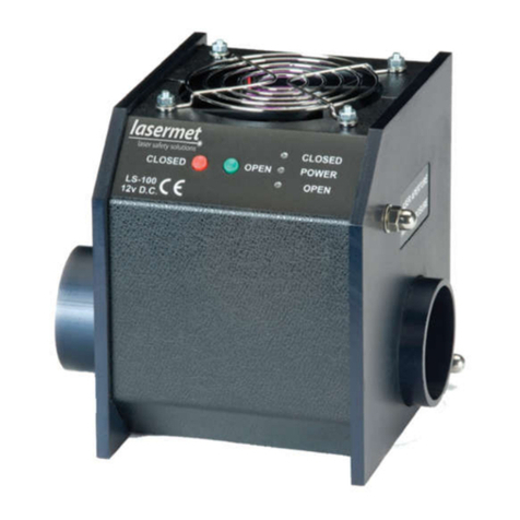
Laser Shutter Supply (12 VDC 0.8 A maximum or 24 VDC, 3 A maximum)
The ICS-6 has a built-in DC supply for operating laser shutters and is able to provide both continuous
and switched supplies using one of the Interlock Operator outputs. Several shutters of the same
type may all be powered from one Interlock Operator contact, please contact Lasermet for details if
required.
Note. The selected Interlock Operator used for switching shutters must not be used for any other
purpose.
If your shutter power requirements exceed 0.8 A at 12V or 3A at 24VDC, or if there is additional
equipment such as low voltage warning signs or door locks powered by the ICS-6, the ICS-6 internal
power supply may be insufficient. The maximum total load that may be placed on the internal
power supply is 4A, which includes any other equipment being run from the 24V supply, such as
door locks, signs etc.
In such cases the shutter may be run from a separate power supply. The mains input of this power
supply is connected to the L OUT and N OUT terminals of the mains terminal block J9. The PSU
output is fed through the interlock operator terminals to operate the shutter. Please contact
Lasermet for suitable power supplies and assistance.

ICS-6 Instruction Manual
01000-53-000 Page 20 of 42 Issue 11 19 January 2021
Shutter
Continuous Supply
Sw itched Supply
0V
+24V
+24V
+12V
+12V
0V
0V
INTERLOCK
OPERATOR
1, 2 OR 3
DC
POWER
OUT
Select appropriate supply voltage
LS-10 uses 12 or 24V.
LS-100 uses 12V.
12
3
12
3
Plug
Distribution
Box
Viewed from
front
Lead
Socket
LS-10 Shutter
Use the above circuit set to 24VDC. The Continuous Supply wire (pin 3) may be omitted for standard
LS-10 shutters.
LS-100 Shutter
Use this circuit set to 12VDC. The Continuous Supply wire must be included to allow the cooling fan
of LS-100 to operate.
LS-20 Shutter
The LS-20 Shutter can use the above circuit set to 24VDC. However, it is recommended that the
monitoring circuit shown below is included to allow the ICS-6 to monitor the shutter and to detect
any faults.
If using the LS-20 SIL3 twin shutter the circuit below must be used to achieve the SIL3 / PL ‘e’ rating.
Other manuals for ICS-6
1
Table of contents
Other Lasermet Measuring Instrument manuals