Lasko 1880 Owner's manual

2085381
1
Rev. D 2/05 (BREEZE)
Rev. D 2/05 (BREEZE) 20853818
18" REMOTE PEDESTAL FAN
MODEL 1880
MODELO 1880
1. Read all instructions before using Fan.
2. Make certain that the power source conforms to the electrical
requirements of the Fan.
3. Use this Fan only as described in this manual. Any other use
not recommended by the manufacturer may cause fire,
electrical shock, or injury to persons.
4. To reduce the risk of personal injury and electric shock, the
Fan should not be played with or placed where small
children can reach it.
5. Unplugpowercordbeforeinstalling,servicing,ormovingtheFan.
WARNING: DO NOT DEPEND UPON THE ON-OFF
SWITCH AS THE SOLE MEANS OF DISCONNECTING
POWER WHEN INSTALLING OR SERVICING THE FAN.
ALWAYS UNPLUG THE POWER CORD.
6. This Fan must NOT be used in potentially dangerous locations
suchasflammable,explosive,chemical-ladenorwetatmospheres.
7. DO NOT use Fan in or near a window. Rain may create an
electrical hazard.
8. Completely assemble Fan, according to instructions, before
connecting to power supply.
WARNING: THIS APPLIANCE HAS A POLARIZED PLUG
(ONE BLADE ISWIDER THAN THE OTHER).TO REDUCE
THE RISK OF ELECTRIC SHOCK, THIS PLUG IS
INTENDEDTO FIT IN A POLARIZED OUTLET ONLY ONE
WAY. MATCH WIDE BLADE OF PLUG TO WIDE SLOT,
FULLY INSERT. IFTHE PLUG DOES NOT FIT FULLY INTO
THE OUTLET, REVERSE THE PLUG. IF IT STILL DOES
NOT FIT, CONTACT A QUALIFIED ELECTRICIAN. DO NOT
ATTEMPT TO DEFEATTHIS SAFETY FEATURE.
WARNING: THIS PLUG IS A SAFETY DEVICE. TO
REDUCE THE RISK OF FIRE, SHOCK, AND PERSONAL
INJURY, DO NOT REMOVE, REPLACE, REPAIR OR
TAMPERWITHTHE ORIGINALLY SUPPLIED PLUG. IFTHE
FAN DOES NOT FUNCTION PROPERLY, IT MAY BE DUE
TOTHE SAFETY DEVICE INCORPORATED INTHIS PLUG.
RETURN TO AN AUTHORIZED SERVICE CENTER OR
CALL 800-233-0268, MONDAY THRU FRIDAY, BETWEEN
8:00AM AND 5:00PM EST. IFTHE PLUG WARNING LABEL
IS MISSING OR DAMAGED, CALL THE TOLL FREE
NUMBER FOR A REPLACEMENT LABEL.
9. Where possible, avoid the use of extension cords. If they
must be used, minimize the risk of overheating by ensuring
that they are UL listed. Never use a single extension cord
to operate more than one Fan.
10.Do not operate any Fan with a damaged cord or plug or after
the Fan malfunctions, has been dropped or damaged in any
manner. Return Fan to authorized service facility for
examination, electrical or mechanical adjustment or repair.
11.Do not insert or allow fingers or foreign objects to enter any
ventilation or exhaust opening as it may cause an electric
shock or fire, or damage the Fan. Do not block or tamper with
the Fan in any manner while it is in operation.
12.Always place the Fan on a stable, flat, level surface when
operating, to avoid the chance of the Fan overturning. Locate
the Power Cord so the Fan or other objects are not resting on
it. DonotrunPower Cord under carpeting. DonotcoverPower
Cordwith throwrugs, runners, or the like. Arrange Power Cord
away from room traffic and where it will not be tripped over.
13.This Fan is not intended for use in wet or damp
locations. Never locate a Fan where it may fall into a
bathtub or other water container.
14. Do not use Fan outdoors.
WARNING: REDUCETHE RISK OF FIRE OR ELECTRIC
SHOCK – DO NOT USETHIS FAN WITH ANY SOLID STATE
SPEED CONTROL DEVICES.
This Fan is for residential use only.
It is not intended to be used in commercial or industrial settings.
GENERAL SAFETY INFORMATION
When using electrical appliances,
basic precautions should always be followed
to reduce the risk of fire, electric shock and injury to persons,
including the following:
READ AND SAVE THESE INSTRUCTIONS
READ CAREFULLY BEFORE ATTEMPTING TO ASSEMBLE, INSTALL, OPERATE OR MAINTAIN THE PRODUCT DESCRIBED.
PROTECT YOURSELF AND OTHERS BY OBSERVING ALL SAFETY INFORMATION. FAILURE TO COMPLY WITH
INSTRUCTIONS COULD RESULT IN PERSONAL INJURY AND/OR PROPERTY DAMAGE!
RETAIN INSTRUCTIONS FOR FUTURE REFERENCE.
IMPORTANT INSTRUCTIONS -
OPERATING MANUAL
SAVE THESE INSTRUCTIONS
SI NECESITA PIEZAS ADICIONALES FAVOR DE COMUNICARSE CON EL FABRICANTE POR LA GARANTIA DEL REMPLAZO DE PIEZAS.
INCLUYA UNA COPIA DE LA PRUEBA DE COMPRA, EL TIPO Y ESTILO DEL VENTILADOR, ESTA INFORMACION PUEDE LOCALIZARLA EN
LA PARTE DE ABAJO DE LA UNIDAD.
ESTE PRODUCTO ESTA GARANTIZADO CONTRA DEFECTOS DE FABRICACIONY/O MATERIALS POR UN AÑO A PARTIR DE LA FECHA DE
COMPRA. A NUESTRA OPCION, PIEZAS QUE SE COMPRUEBEN QUE ESTEN DEFECTUOSAS SERAN REPARADAS. REMPLAZADAS O SE
REMPLAZARA EL PRODUCTO POR COMPLETO.
SINECESITAREPARACIONESELECTRICAS O MECANICASDURANTEELPERIODODEGARANTIA, ENVIE LAUNIDADPORCORREOO FLETE
PAGADO AL CENTRO DE SERVICIO MAS CERCANO, LISTADO EN ESTA TARJETA.
SI SOLAMENTE NECESITA REMPLAZAR UNA PIEZA, TIENE QUE INDICAR EL TIPO Y ESTILO DEL VENTILADOR, ESTA INFORMACION SE
ENCUENTRA EN LA PARTE DE ABAJO DE LA UNIDAD. DE CUALQUIER FORMA, SE SOLICITA UNA COPIA DE LA PRUEBA DE COMPRA.
ESTAGARANTIANOESVALIDASIELDANO OCURRE DEBIDO A UN ACCIDENTE, MANEJO,INSTALACION,OPERSCIONINCORRECTA,DANO
DURANTE EL TRANSPORTE, MALTRATO, USO INDEBIDO, REPARACIONES HECHAS O INTENTADAS NO AUTHORIZADAS, O EL USO DEL
PRODUCTO PARA FINES COMERCIALES.
TODAS LAS GARANTIAS EXPRESAS O IMPLICITAS, TIENEN UNA DURACION DE UN ANO A PARTIR DE LA FECHA DE COMPRA ORIGINAL.
ESTA GARANTIA EXPRESAS O IMPLICITAS, TIENEN UNA DURACION DE UN ANO A PARTIR DE LA FECHA DE COMPRA ORIGINAL. ESTA
GARANTIA NO CUBRE RESPONSABILIDADES POR DANOS PORTUITOS O CONSECUENTES POR NINGUNA CAUSA.
DADO QUE ALGUNOS ESTADOS NO PERMITEN NINGUNA LIMITACION EN LA DURACION DE UNA GARANTIA IMPLICADA, O LA EXCLUSION
ORESTRICCION DEDANOSFORTUITOSOCONSECUENTES.LALIMITACIONOEXCLUSIONANTESMENCIONADAPODRIA SER NO VALIDA.
ESTAGARANTIA EXTIENDE AL COMPRADOR ORIGINAL DERECHOS LEGALES ESPECIFICOS Y USTED PODRIATENEROTROSDERECHOS,
LOS CUALES VARIAN DE UN ESTADO A OTRO.
GARANTIA LIMITADA - NO ES VÁLIDA EN MÉXICO
PARA PIEZAS:
Para Repuestos Llame al: 1-800-233-0268. DE LUNES A VIERNES, DESDE LAS 8 DE LA MAÑANA A LAS 5 DE
LA TARDE, HORA DEL ESTE. "POR FAVOR NO DEVUELVA EL PRODUCTO AL SITIO DONDE LO COMPRÓ".
Cuando llame, refiérasa al tipo y estilo del producto (situados en la base del producto).
PARA OBTENER ASISTENCIA TÉCNICA Y LAS DIRECCIONES DEL CENTRO DE SERVICIO:
Para cualquier pregunta, comentarios o para obtener la dirección de su centro de servicio más cercano, SÍRVASE
LLAMAR A NUESTRO "TELÉFONO DE EMERGENCIA" GRATUITO AL 1-800-233-0268, DE LUNES A VIERNES,
DESDE LAS 8 DE LA MAÑANA A LAS 5 DE LA TARDE, HORA DEL ESTE. Cuando llame, refiérasa al nombre y
número de modelo del producto
Departamento de Servicio para Equipos • 300 Confederate Drive Franklin, TN 37064
¡POR FAVOR, NO ENVÍE EL PRODUCTO A ESTA DIRECCIÓN!
Para más información, por favor visite nuestro sitio web: www.laskoproducts.com
MANTENIMIENTO
ADVERTENCIA: SIEMPRE DESCONECTE EL
ENCHUFE ANTES DE MOVER O PROPORCIONAR
SERVICIO AL VENTILADOR.
ADVERTENCIA: ¡NO SUMERJA ELVENTILADOR EN AGUA!
LIMPIEZA: Limpie las aberturas de toma de aire y escape del
Ventilador con un aditamento de cepillo en su aspiradora. Esto
eliminará la suciedad y el polvo que se pueden acumular con el
paso del tiempo. NO INTENTE DESARMAR EL VENTILADOR.
Limpie el cuerpo del Ventilador con un paño suave.
ADVERTENCIA: No use gasolina, bencina, acetona,
limpiadores abrasivos,etc., puesto que eso dañará elVentilador,
NUNCA use ALCOHOL o SOLVENTES.
SERVICIO: Cualquier otro servicio, con la excepción de
mantenimiento general por parte del usuario, deberá ser realizado
por un representante de servicio autorizado. Llamar al 1-800 -233-
0268, de lunes a viernes, entre las 8 a.m. y las 5 p.m. (Horario
Estándardel Estede los EstadosUnidos), paraaveriguarla dirección
de su centro de servicio más cercano.
ALMACENAMIENTO: Guarde elVentilador,con estasinstrucciones,
en su caja original en un lugar fresco y seco.
INCLINACION: Este Ventilador está equipado de Cabeza de
Ventilador de ángulo múltiple para la Circulación del aire por
toda habitación o cuarto. Siga lo que se indica a continuación
para graduar propiamente el "ángulo de inclinación" del
Ventilador.
(Figura 16)
1.Ponga una mano sobre el soporte exactamente por debajo del
Cuello del Ventilador.
2.Ponga la otra mano sobre la parte superior del Ventilador.
3.Empuje o hale suavemente la Cabeza del Ventilador hasta que
quede en la posición deseada.
Figura 16

Botón Alimentación/
Velocidad
7
Rev. D 2/05 (BREEZE) 2085381
1. Take pipe assembly out of carton as shown.
(Figure 1)
2. Loosen
Height Adjustment Nut
turning counter clockwise.
(Figure 2)
3. Raise
Extension Pipe
.
(Figure 3)
4. Tighten
Height Adjustment Nut
turning clockwise.
(Figure 4)
STEP 1: PIPE ASSEMBLY
STEP 2: STAND ASSEMBLY
PLACE BASE FLAT ON FLOOR
1. With a twisting motion, insert the end of the large diameter
pipe into hole in
Base
.
(Figure 5)
Turning pipe while push-
ing will assure pipe is fully seated in
Base
.
2. For Height Adjustment:
a) Loosen
Height Adjustment Nut
.
b)Raise or lower
Extension Pipe
to desired height.
c) Tighten
Height Adjustment Nut
.
1. Place
Head Assembly
with
Collar
onto
Extension Pipe
.
(Figure 6)
2. Holding
Extension Pipe
firmly, twist
Head Assembly
downward until seated on
Extension Pipe
.
1. Tilt
Head Assembly
back. Put
Rear Grill
on Motor.
(Figure 7)
2. Align tab of Plastic
Rear Grill
with groove on top of front
Motor
cover.
STEP 4: BLADE & GRILL ASSEMBLY
3. Fully seat
Rear Grill
and secure with
Plastic Nut
turning Clock-
wise. Slide
Blade
onto
Motor Shaft.
(Figure 8)
Align
Groove
on
blade hub with
Pin
on motor shaft.
(Figure 8A)
4. Tosecure
Blade
,screw
Spinner
onto
Shaft Counter Clockwise until tight on
Blade hub.
Figure 2 Figure 4
Figure 3
Figure 1
Height
Adjustment
Nut
Extension
Pipe
STEP 3: HEAD ASSEMBLY
Figure 5
Extension Pipe
Height
Adjustment Nut
Base
Head
Assembly
Collar
Extension
Pipe
Figure 6
2085381
Rev. D 2/05 (BREEZE) 2
Rear
Grill
Figure 7
Motor
Rear Grill
Figure 8
Blade
Fan
Spinner
Plastic
Nut
Figure 8A
Pin
Groove
+
+
TM
Intervalo Del
Temporizador
EsteVentiladorpuedehacersefuncionarmediantelosControles
Manuales ubicados en la parte superior de la unidad (como se
muestra en la
Figura 11
) o con el Control Remoto (se muestra
en la
Figura 12
).
1. Retire el Ventilador de la caja y arme según las instrucciones.
2. Coloque el Ventilador sobre una superficie firme y plana.
ADVERTENCIA: Los topes de plástico o de goma, como los
pies de esta unidad, pueden adherirse a los pisos de madera dura.
La unidad puede dejar un residuo que podría oscurecer, manchar o
producir defectos permanentes en la terminación de ciertos pisos
de madera dura.
3. Conecte el cable a un tomacorrientes eléctrico de 120 V~.
Asegúrese que el enchufe se introduzca firmemente en el
tomacorrientes.
4.InstalelasdosbateríasAAA suministradas de la manera indicada
en la Figura 12.
5. Conecte la energía eléctrica a su ventilador pulsando el
Botón
Alimentación/Velocidad
() en el ventilador, o el
Botón
Alimentación
( ) en el control remoto.
6. VELOCIDAD DEL VENTILADOR: Ahora puede ajustar la
velocidad del ventilador al nivel deseado - 1 (baja), 2 (mediana) ó
3 (alta) - pulsando el
Botón Alimentación/Velocidad
( )en el
ventilador o el
Botón Alimentación
() en el control remoto.
7. FUNCIÓN DE TEMPORIZADOR: Este ventilador tiene un
temporizadorquelepermitefijareltiempodefuncionamientopulsando
el
BotónFunción de Temporizador
( ),ubicadoen la zona delos
controles en el ventilador, o pulsando el
Botón Función de
Temporizador
( ) en elcontrolremoto.Pulselateclaunavezpara
una hora de funcionamiento, dos veces para dos horas y tres veces
para cuatro horas. Si se pulsa por cuarta vez, el ventilador vuelve al
modo de funcionamiento continuo.
8. MODODEBRISA: Elmododebrisapermitequeelventiladorcambie
demaneraaleatoriaentrelasdistintasvelocidades.Conelventilador
encendido, pulse el
Botón Modo de Brisa
( )
en el ventilador, o
pulse el
Botón Modo de Brisa
( )
en el control remoto. Si se ha
ajustado la velocidad del ventilador en baja (1), cambiará entre
apagadoybaja.Sisehaajustadoenvelocidadmediana(2),cambiará
entre apagado, baja y mediana. Si se ha ajustado en velocidad alta
(3),cambiará entreapagado, baja, mediana y alta.La luzindicadora
de velocidad destella en el modo de brisa. Pulse el
Botón Modo de
Brisa
()
nuevamente para desactivar el modo de brisa.
9. OSCILACION:Empujelaperillaubicadaenlapartesuperiorde la
caja del motor para hacer que la cabeza del Ventilador se mueva
de un lugar hacia otro.
(Figuras 13 y 14)
10.Su ventilador de pedestal con control remoto tiene, además,
Tiras de Fijacíon
. Quite la
Película Protectora
del dorso de la
FUNCIONAMIENTO
6.Conelcabezaldelventiladorenposiciónvertical,alineeel
Adorno
de
la
Parrilla Delantera
de modo que quede horizontal y con el lado
debidohacia arriba.Empiece en laparte superior dela parrillay siga
hacia abajo, insertando las
Trabas
de la
Parrilla Trasera
en las
Ranuras
de la
Parrilla Delantera
.
(Figura 9)
Adorno
Ranuras
Trabas Parrilla
Trasera
Parrilla
Delantera
Figura 10
5.Install the
Ornament
into the
Front Grill
. Peel the adhesive back
off the
Ornament
. Insert
Tab
into rectangular Slot. Press
Orna-
ment
into place.
(Figure 9)
Figure 9
Slot
Ornament
Tab
Front Grill
piezacuadradadeTirasde Fijacíony adhiérala al controlremoto.
Quite la película protectora del dorso de la otra pieza cuadrada
de Tiras de Fijacíon y adhiérala a su ventilador. Ahora puede
guardar su control remoto cuando no lo esté usando.
(Figura 15)
Botón Modo
de Brisa Botón Función de
Temporizador
Figura 11
Figura 12
Botón Función
De Temporizador Botón Función De Brisa
Botón
Alimentación
Botón Velocidad
Baterías
AAA
Hacia Arriba:
Estacionario Hacia Adelante: Oscilar
Figura 10 Figura 11
Tiras De Fijacíon
Película
Protectora
Adhesivo

1. Inclinarla
Cabeza del Ventilador
hacia atrás. Coloque la
Rejilla
Trasera
en el
Motor. (Figura 7)
2. Alinear la lengüeta de la
Rejilla Trasera
con la ranura en la parte
superior de la cubierta delantera del
Motor
.
PASO 4: ENSAMBLE DEL ASPAY REJILLA
PASO 2: ENSAMBLE DEL PIE
COLOQUE LA BASE EN EL PISO
1. Utilizando un movimiento giratorio, inserte el extremo del tubo de
diámetro grande en el agujero de la
Base. (Figura 5)
El girar el tubo
a medida que se lo empuja asegura que el tubo quede plenamente
asentado en la
Base
.
2. Para ajustar la altura:
a) Afloje la
Tuerca de Ajuste de Altura
.
b) Eleve o baje el
Tubo de Extensión
hasta obtener la altura
deseada.
c) Apriete la
Tuerca de Ajuste de Altura
.
1. Coloque el
Conjunto de Cabezal
con el
Collar
en el
Tubo de
Extensión. (Figura 6)
2.Sostenga firmemente el
Tubo de
Extensión
yempujeel
Conjunto
de Cabezal
hacia abajo con un
movimiento giratorio hasta que
quede asentado en el
Tubo de
Extensión
.
PASO 3: CONJUNTO DE LA CABEZA
1. Saque el conjunto de la tubería del cartón como muestra.
(Figura 1)
2. Desafloje la
Tuerca de Ajuste de Altura
, girando en sentido
contrahorario.
(Figura 2)
3. Eleve la
Extensión De LaTubería.
(Figura 3)
4. Apriete la
Tuerca de Ajuste de Altura
, girando en sentido
horario.
(Figura 4)
PASO 1: ARMADO DE LA TUBERÍA
3. Asientela
ParrillaTrasera
ysujetelacon la
Tuercade Plástico
hacialaDerecha. Deslice la
Helice
enel Eje del
Motor
.
(Figura
8)
Alinearla
RanuraDelCubo
delatapaconel
Pasador
deleje
del motor.
(Figura 8A)
4. Para asegurar la
Helice
, enroscarla
hastaque quede apretada enel
Cubo
de la Tapa
haciéndola girar Hacia la
Izuierda.
2085381
Rev. D 2/05 (BREEZE) 62085381
Rev. D 2/05 (BREEZE) 3
Conjunto de
Cabezal
Figura 2 Figura 4Figura 3
Figura 1
Tuerca de
Ajuste de
Altura
Tubería de
Extension
Figura 5
Tubo de Extensión
Tuerca de Ajuste
de Altura
Base
Collar
Tubo de
Extensión
Figura 6
Rejilla
Trasera
Figura 7
Motor
Figura 8
Parrilla Trasera Helice
Tuerca de
Plastico
Tapa de
Ventilador
Figura 8A
Pasador
Ranura del
Cubo
This Fan may be operated by the Manual Controls located on top
of the unit (as shown in
Figure 11
) or by the Remote Control
(shown in
Figure 12)
.
1. Remove the Fan from the carton and assemble as instructed.
2. Place the Fan on a firm, level surface.
WARNING: Plastic or rubber tabs, like the feet on this unit, may
stick to hardwood floors. The unit may leave a residue that could
darken, stain or leave permanent blemishes on the finish of certain
hardwood floors.
3. Plug the power supply cord into a 120 V~ electrical outlet. Be
sure plug fits tightly in outlet.
4. Install two AAA batteries supplied as shown in
Figure 12
.
5. Apply power to your fan by pushing the
Power/Speed Button
( )
manuallyon the fan,orthe
Power Button
( )on the remote control.
6. FAN SPEED: You may now adjust the fan speed to the desired
level, 1 (Low), 2 (Medium), or 3 (High) by pressing the
Power/
Speed Button
( )Power/Speed button on the fan or by pressing
the
Speed Button
( ) on the remote .
7. TIMING FUNCTION: This fan is equipped with a timer that
allows you to set the length of operation by pressing the
Timing Function Button
( ) manually on the control area
of the fan, or by pressing the
Timing Button
() on the
remote control. Press the key once for one hour, twice for
two hours, a third time for four hours. A fourth time will
reset the fan to continuous running mode.
8. BREEZE MODE: The Breeze Mode allows the fan to ran-
domly cycle through the speeds. With the fan on, press the
Breeze Mode Button
( ) on the control area of the fan, or
the
Breeze Button
( ) on the remote control. If the fan speed
setting is on Low speed (1), it will cycle from off to low. Me-
dium speed (2) will cycle from off, low and medium. High
speed (3) will cycle from off, low, medium and high.The speed
indicator light will flash in Breeze Mode. Press the
Breeze
Mode Button
( ) again to turn off the Breeze Mode.
9. OSCILLATION: Push down oscillation knob on motor housing
to make fan head move from side to side.
(Figures 13 and 14)
10.Your Remote Pedestal Fan has also been provided with
Attach-
ment Strips
. Remove the
Film
from rear of Attachment Strip
and adhere to remote. Remove Film from rear of the other At-
tachment Strip and adhere to your fan.Now you can store your
remote control when not in use.
(Figure 15)
OPERATION
+
+
TM
Figure 11
Timer Length
6. With fan head in upright position, align
Ornament
of
Front Grill
so it is horizontal and right side up. By starting with the top of
the grill and working down, insert
Snaps
on
Rear Grill
through
Slots
in
Front Grill
.
(Figure 10)
Ornament
Slots
Snaps
Rear Grill
Front Grill
Figure 10
2.Instale el Ornamento en la Parrilla Delantera. Despegue el
autoadhesivo del Ornamento. Inserte la Lengüeta en la Ranura
Rectangular. Presione el Ornamento hasta que quede fijo.
(Figura
8)
Ranura
OPERATION
Down: Oscillate
Up: Stationary
Figure 13 Figure 14
Power / Speed
Button
Timing Function
Button
Breeze Mode
Button
Figure 12
Breeze Mode
Button
Power
Button
Speed Button
Timer
Function
Button
AAA
Batteries
Attachment
Strips
Figure 15
Adhesive
Film
Ornamento
Lengüeta
Figura 9

SHOULD ACCESSORY PARTS BE NEEDED, CONTACT THE MANUFACTURER FOR IN-WARRANTY
REPLACEMENT PARTS. A COPY OF PROOF-OF-PURCHASE MUST BE INCLUDED ALONG WITH THE
TYPE AND STYLE, WHICH IS LOCATED ON THE BOTTOM OF YOUR APPLIANCE.
This product is warranted for one year from the date of original purchase against defects in workmanship and/or
materials. At our option, parts that prove to be defective will either be repaired or replaced or the whole product
will be replaced.
Shouldelectricalormechanicalrepair becomenecessaryduringthewarrantyperiod,send yourcompleteproduct,
postageor freightpre-paid tothenearestservicecenter.Callthe numberbelow fortheservicestationnearestyou.
Should a part need replacement, you must give us the type and style of your appliance. You will find this at the
bottom of the appliance. In either case, a copy of your proof of purchase is requested.
This warranty does not apply if the damage occurs because of accident, improper handling or operation, shipping
damage,abuse,misuse,unauthorizedrepairsmadeorattempted,ortheuseoftheproductforcommercial service.
ALL WARRANTIES, EXPRESSED OR IMPLIED, LAST FOR ONE YEAR FROM THE DATE OF ORIGINAL
PURCHASE. THIS WARRANTY DOES NOT COVER LIABILITY FOR INCIDENTAL OR CONSEQUENTIAL
DAMAGES FOR ANY CAUSE WHATSOEVER.
Some states do not allow limitations on how long any implied warranty lasts, or the exclusion or limitation of
incidental or consequential damages, so that the above limitations and exclusions may not apply to you. This
warranty gives you specific legal rights. You may also have other rights which vary from state to state.
LIMITED WARRANTY - NOT VALID IN MEXICO
FOR PARTS:
For Replacement Parts please call: 1-800-233-0268. MONDAY THROUGH FRIDAY, BETWEEN THE HOURS OF 8 AM
AND 5 PM EST. "PLEASE DO NOT RETURN PRODUCT TO PLACE OF PURCHASE."
Reference the type and style of product (located on the underside of the product) when you call.
FOR TECHNICAL ASSISTANCE and SERVICE CENTER LOCATIONS:
For any questions, comments or the location of your nearest service center, PLEASE CALL OUR TOLL-FREE
"HOTLINE" AT 1-800-233-0268. MONDAY THROUGH FRIDAY, BETWEEN THE HOURS OF 8 AM AND 5 PM EST.
Please reference product name and model no. when you call.
Appliance Service Dept. • 300 Confederate Drive Franklin, TN 37064
PLEASE DO NOT SEND PRODUCT TO THIS LOCATION!
For more information please visit our website: www.laskoproducts.com 2085381
Rev. D 2/05 (BREEZE) 42085381
Rev. D 2/05 (BREEZE) 5
MODEL 1880
VENTILADOR DE PEDESTAL DE 18
PULGADAS CON CONTROL REMOTO
MODELO 1880
1. Lea todas las instrucciones antes de utilizar el Ventilador.
2. Cerciórese de que la fuente de poder sea compatible con las
demandas eléctricas del Ventilador.
3. Use este Ventilador sólo en la forma que se describe en el manual.
Cualquierotrousonorecomendadoporelfabricantepodríaocasionar
un incendio, golpes de electricidad o lesiones a personas.
4. Paradisminuirelriesgodelesionesfísicasygolpesdeelectricidad,
no debe jugarse con el ventilador no deberá éste ser ubicado al
alcance de los niños pequeños.
5. Desenchufe el cable eléctrico antes de instalar, proporcionar
servicio o mover el Ventilador.
ADVERTENCIA: NO DEPENDA DEL INTERRUPTOR DE
ENCENDIDO-APAGADO COMO EL ÚNICO MEDIO PARA
DESCONECTAR LA POTENCIA AL INSTALAR O
PROPORCIONARLE SERVICIO AL VENTILADOR.
DESENCHUFE SIEMPRE EL CABLE ELÉCTRICO.
6. Este Ventilador NO debe usarse en ubicaciones potencialmente
peligrosas, tales como en ambientes inflamables, explosivos,
cargados de sustancias químicas o húmedos.
7. NO use el Ventilador en o cerca de una ventana. La lluvia puede
generar riesgos eléctricos.
8. Vuelva a armar el ventilador por completo, siguiendo las
instrucciones, antes de reconectarse a la fuente de poder.
ADVERTENCIA:ESTE ARTEFACTOPOSEE UNENCHUFE
POLARIZADO (UNA ESPIGA ES MÁS ANCHA QUE LA
OTRA). PARA DISMINUIR EL PELIGRO DE GOLPES DE
ELECTRICIDAD,ESTEENCHUFEDEBERÁ INTRODUCIRSE
EN UN TOMACORRIENTE POLARIZADO SÓLO DE UNA
FORMA.HAGAENCAJARTOTALMENTELAESPIGA ANCHA
DEL ENCHUFE EN LA RANURA ANCHA. SI EL ENCHUFE
NO ENCAJA POR COMPLETO EN EL TOMACORRIENTE,
INVIERTA EL ENCHUFE. SI AUN ASÍ NO ENCAJA,
CONTACTEAUN ELECTRICISTA CALIFICADO.NOINTENTE
BURLAR ESTA FUNCIÓN DE SEGURIDAD.
ADVERTENCIA: ESTE ENCHUFE ES UNA MEDIDA DE
SEGURIDAD.PARA REDUCIR EL RIESGO DE INCENDIO,
CHOQUE ELÉCTRICO Y LESIONES PERSONALES, NO
QUITE, NI REEMPLACE, NI REPARE O ALTERE EL
ENCHUFE QUE SE PROVEE ORIGINALMENTE. SI EL
VENTILADOR NO FUNCIONA CORRECTAMENTE, PUEDE
DEBERSE AL DISPOSITIVO DE SEGURIDAD
INCORPORADO EN ESTE ENCHUFE. REGRESE A UN
CENTRO DE SERVICIOS AUTORIZADO O LLAME AL 800-
233-0268, DE LUNES AVIERNES ENTRE LAS 8.00 A.M.Y
LAS 5.00 P.M. EST. SI LA ETIQUETA DE ADVERTENCIA
DEL ENCHUFE FALTA O ESTA DAÑADA, LLAME AL
NÚMERO DE CONSULTA GRATUITO PARA PEDIR UNA
ETIQUETA DE REEMPLAZO.
9. De ser posible, evite el uso de cables de extensión. Si debieran
usarse, minimice el riesgo de sobrecalentamiento procurando
que estén aprobados por UL. Nunca use un solo cable de
extensión para hacer funcionar más de un Ventilador.
10.No haga funcionar ningún Ventilador con un cable o enchufe
dañadoodespuésdequeelventiladorpresentealgúndesperfecto
ohayasidodejadocaero sufriera cualquiertipodedaño.Regrese
elVentiladoraunserviciodereparaciónautorizadoparaexaminar
elVentilador,efectuarleajusteseléctricosomecánicosorepararlo.
11.No introduzca ni permita que se introduzcan dedos u objetos
extrañosenningunaaberturadeventilacióno escape,puestoque
podría provocar un golpe de electricidad, incendio, o daños al
ventilador. No bloquee ni manipule el Ventilador de ninguna
manera mientras esté en funcionamiento.
12.Siempre coloque el Ventilador sobre una superficie, estable,
planayhorizontal mientras esté enfuncionamiento,para evitarla
posibilidad de que el Ventilador se dé vuelta. Ubique el cable
eléctricodetalmodoqueelventiladoruotrosobjetosnodescansen
sobre él. No disponga el cable eléctrico debajo de alfombras. No
cubraelcableeléctricocontapetes,alfombrascontinuasuobjetos
similares.Coloqueelcableeléctricofueradelpasodelaspersonas
y donde nadie se tropiece con el mismo.
13.EsteVentiladornohasido diseñadoparausarseenlugaresmojados
ohúmedos.NuncacoloqueunVentiladordondequepalaposibilidad
de que caiga en una bañera u otro recipiente con agua.
14.No use el Ventilador en exteriores.
ADVERTENCIA: DISMINUYA EL RIESGO DE INCENDIO
O GOLPES DE ELECTRICIDAD – NO USE ESTE
VENTILADOR CON ARTEFACTOS DE CONTROL DE
VELOCIDAD EN ESTADO SÓLIDO.
Este Ventilador es para uso residencial únicamente.
No está destinado para uso en ambientes comerciales o industriales.
INFORMACIÓN GENERAL DE SEGURIDAD
Al usar aparatos eléctricos, las precauciones básicas de seguridad deberan
siempre de seguirse para reducir el riesgo de incendio, choque eléctrico, y
daño a personas, incluyenda las siguientes:
INSTRUCCIONES IMPORTANTES -
MANUAL DE USO
CONSERVE ESTAS INSTRUCCIONES
LEA Y GUARDE ESTAS INSTRUCCIONES
LEA CUIDADOSAMENTE LAS INSTRUCCIONES ANTES DE INTENTAR ARMAR, INSTALAR, USAR O DAR
MANTENIMIENTO AL PRODUCTO DESCRITO.
PROTÉJASE A SÍ MISMOY A LOS DEMÁS CUMPLIENDO CONTODA LA INFORMACIÓN DE SEGURIDAD. EL NO
SEGUIR LAS INSTRUCCIONES PODRÍA RESULTAR EN LESIONES PERSONALES Y/O DAÑOS A LA PROPIEDAD.
CONSERVE LAS INSTRUCCIONES COMO FUTURA REFERENCIA.
WARNING: ALWAYS UNPLUG CORD BEFORE CLEANING
OR DISASSEMBLING.
WARNING: DO NOT IMMERSE FAN IN WATER!
CLEANING: IMPORTANT! DO NOT immerse electrical parts in
water! Disassembled grills may be immersed to be cleaned with a
mild detergent and water. Wipe all other parts with soft cloth
moistened with water and mild detergent only. DRY ALL PARTS
COMPLETELY BEFORE REASSEMBLING. After any maintenance
or servicing, completely reassemble unit as described in this
instruction manual before reconnecting to the power supply.
CAUTION:Do not use gasoline, benzine, thinner, harsh clean-
ers, etc. as they will damage the Fan. NEVER use ALCOHOL
OR SOLVENTS.
SERVICING: All other servicing, with the exception of general user
maintenance, should be performed by an authorized service repre-
sentative.Call 1-800-233-0268,Monday through Friday, betweenthe
hours of 8:00 a.m.and 5:00 p.m.EST for the location of your nearest
service center.
LUBRICATION: Motor is permanently lubricated.
MAINTENANCE
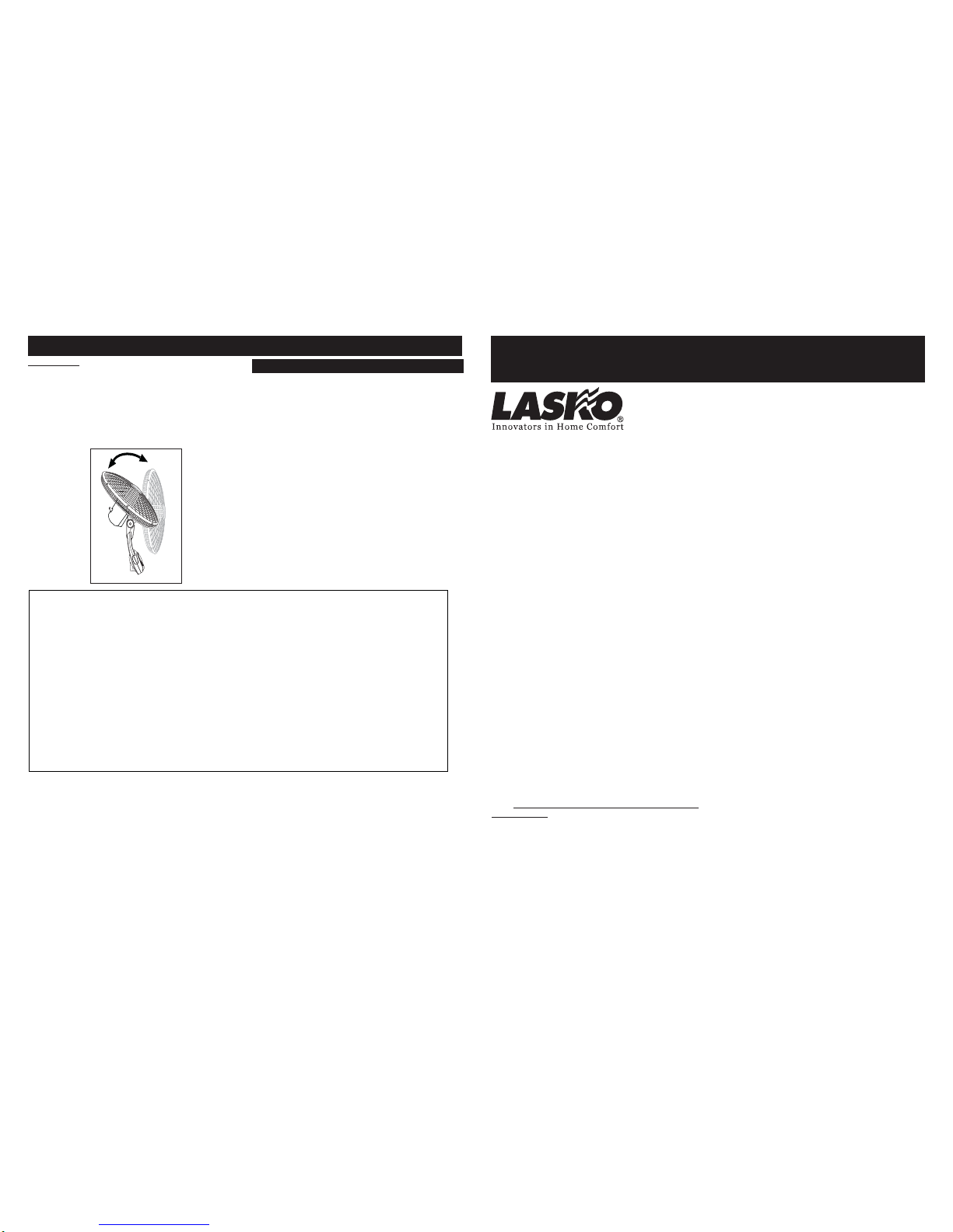
TILTING: This Fanis equipped withamulti-angle FanHead forWhole-
Room Air Circulation. Follow the steps below to properly adjust the
"tilt angle" of your Fan.
(Figure 16)
1. Place one hand on the pole just under the Fan Neck.
2. Place your other hand on top of Fan.
3. GentlypushorpulltheFanHeaduntilitisinthedesiredposition.
Figure 16
Other Lasko Fan manuals
Popular Fan manuals by other brands

Honeywell
Honeywell HT-800E User instructions

Tornado
Tornado HI-FAN-30MOWF-WR-1P instruction manual

Helios
Helios HR 90 K Installation and operating instructions

Amaircare
Amaircare Airwash MultiPRO BOSS AH2000 CART Operating and maintenance manual

Global Industrial
Global Industrial 292655 instruction manual

Vaillant
Vaillant VAE 190/1 RHT installation instructions

Yosemite Home Decor
Yosemite Home Decor LINDSEY owner's manual

Prominence Home
Prominence Home Arthur 52" owner's manual

Regency Ceiling Fans
Regency Ceiling Fans Envoy owner's manual

ElectrIQ
ElectrIQ TF29OSCT8RW user manual

LUCCI
LUCCI AIRFUSION RESORT installation instructions

NuTone
NuTone VENT-A-LITE 668RP Architectural & engineering specifications