1. Introduction
02
Company Profile 01
02
Contents
1.1 Prefix
1.2 Grid-tied PV System
4. Installation 04
04Additional Installation Components
04Required Parts and Tools
04Simple to Install
05Installation Procedure
05Step 1 - Install AC Branch Circuit Junction Box
06
06
06
07
07
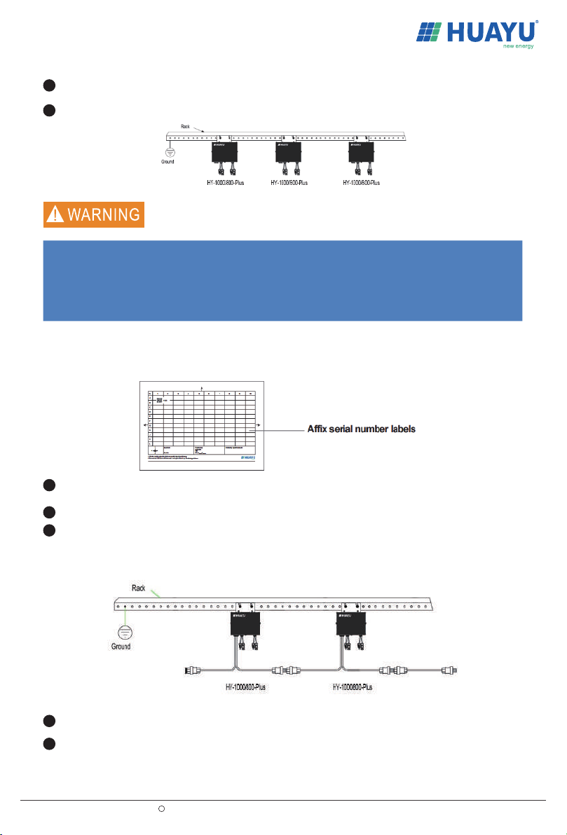
Step 2 - Attach Microinverter to Racking System or the PV Module Frame
Step 3 - Create an Installation Map
Step 4 - Connect the Microinverter in Parallel
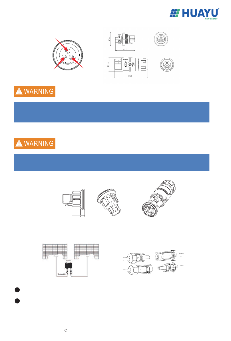
Step 5 - Install an AC Cable Protective End Cap at the End of AC Cable
Step 6 - Connect Microinverter to PV Modules
03
2. Safety Instruction
3. FCC Compliance 03
02
02
1.3 How to Use This Manual
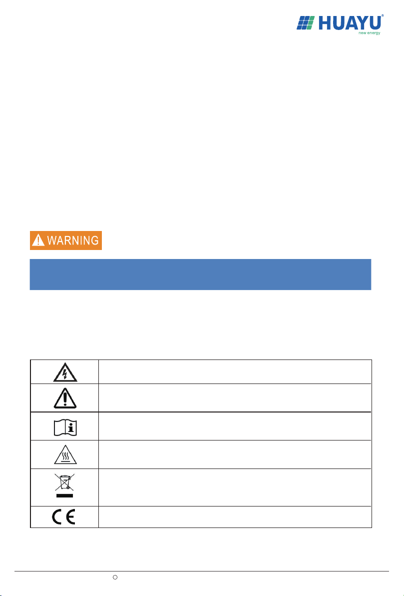
021.4 Label
5. Commissioning
08
6. Operating Instructions 08
7. Troubleshooting Maintenance
8. Specification
09
12