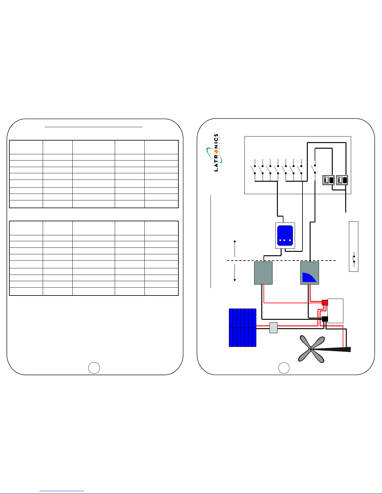
Latronics PV Edge Grid Connect User manual

INSTRUCTION MANUAL
and
WARRANTY REGISTRATION CARD
NO POSTAGE REQUIRED IF
POSTED IN AUSTRALIA
Ph 61 7 5491 6988
A N E W W O R L D P O W E R
®
ANEWWORLDPOWER
®
REPLY PAID MB 1
LATRONICS PTY LTD
P.O. BOX 73
MOFFAT BEACH QLD 4551
AUSTRALIA
Latronics P.O. Box 73 Moffat Beach Qld 4551 AUSTRALIA

WELCOME
Latronics
Latronics
Latronics
Latronics
products are all proudly designed, engineered and
manufactured in Australia. As a specialist sine wave inverter company
we produce Inverters for a diverse range of applications such as;
mining, railways, telecommunications, marine, remote power, motor
homes, and other industrial or commercial installations.
In order to produce the most reliable products available,
Inverters have been designed to endure the most rugged terrain and
the harshest conditions across the Australian continent.
All products are engineered using the latest high quality components
and manufactured to stringent quality standards, thus ensuring
customers all enjoy many years of trouble free operation.
It is important to us at , that our clients enjoy the maximum
benefits from our Inverters in a safe and productive environment. So
we strongly advise that you read through the next few pages of this
manual, which explains all the modes of operation and relevant safety
precautions for your new Power Inverter.
Please remember to complete and return your registration card
on the last page of this manual to validate your warranty.
Please retain your receipt as proof of purchase.
If your Inverter requires service or repair please complete the
Warranty Repair Form on page 20.
LATRONICS
PO BOX 73
MOFFAT BEACH Q 4551
PH: 61 7 5491 6988 FAX: 61 7 5491 6792
EMAIL:
WEB: www.latronics.com
Serial No.................................... Date card returned..............................
IMPORTANT !
Please complete and return this Registration Card to
validate your Warranty
REGISTRATION CARD
Your warranty is only valid if this card is completed & returned within 3 months of the date of purchase.
Name:................................................................................... .Serial No:.................................................
Date of Purchase:............................................Supplier:................................................................................................................
? Residential Commercial
Solar Batteries Wind Other
Features Value for Money Appearance Recommendation Warranty Australian Made
Fair Good Very Good Excellent
Above Expectations Yes No
Comments:...........................................................................
.......................................................................................................................................................................................................
* Where is your Inverter being used
....................................
* Was your decision made because of?
* How do you rate the service from your supplier?
* Did your new Inverter meet your expectations?
.Post code:......................
Email (optional): ...............................................................................
*What Energy Source is connected to your Inverter?
Copyright Latronics. Doc No M70 08/08 Version 5

TABLE OF CONTENTS PAGE
A N E W W O R L D P O W E R
®
WARRANTY REPAIR FORM
Your Name ......................................................Phone.................................
Email............................................................................................................
Your Delivery Address ................................................................................
Your Postal Address ..................................................................................
nverter Serial No ..................................................................................
Have you contacted your system installer?
Do you have a battery bank
What is the capacity of your Battery Bank? ..............Amp hrs
Do you have Battery fuses installed?
Have these Battery fuses been checked?
Was the Inverter case hot when it failed?
Which lights came on when Inverter failed?
What time did your Inverter fail?
What were the weather conditions?
Have you disconnected the battery,
then tried to turn on your Inverter?
Please call *61 7 5491 6988 or email technical@latronics.com to obtain
the address of your nearest service center and your RMA Number which is
essential for efficient processing.
RMA Number........................
Have you attached proof of purchase
We thank you for your time and patience. This information will help us
determining the cause of failure and possible prevention methods.
I
yes no
yes no
yes no
yes no
yes no
100% Overload
(please tick) 75% AC Grid
50% AC Fault
25%
Day night
sunny overcast rainy stormy
yes no
yes no
INSTALLATION
DC WIRING / DC EARTHING
WIRING DIAGRAMS
SPECIAL FEATURES
DIP SWITCH SETTINGS
INVERTER OPERATION
SOLAR INPUT CONFIGURATION
FAULT FINDING
RADIO FREQUENCY INTERFERENCE
WARRANTY CONDITIONS
TECHNICAL SPECIFICATIONS
WARRANTY CARD 20
18
17
16
15
14
13
12
10
7
3
2
20
AC WIRING 5

INSTALLATION
BEFORE INSTALLATION
!
!
Grid Interactive Solar Systems have become increasingly popular in recent
years. These systems do not necessarily require batteries for storage and
therefore can have a very simple configuration.
Ensure the Inverter has not been damaged in transit.
The unit must be placed in a well ventilated and protected area, not exposed
to the open environment, and free from contaminates (i.e. exhaust gases,
sea air, dust etc.).
The PV edge is designed for indoor installation in a suitable location where
ambient temperature will not exceed rated values.
As the PV edge has a wall mountable enclosure, ensure proper air circulation
for cooling of the Inverter.
Safety- DC solar input and AC grid are electrically and galvanically isolated
via the Toroidal Transformer.
It is important that all wiring in the installation complies with the relevant
standards (AS4777) .
!
!
!
!
Any work carried out is to be preformed by
Qualified and Licensed personnel.
1.
219
Photovoltaic Cells
Mains
PV Edge
STATEMENT OF QUALITY ASSURANCE
The whole of the supplies have been subjected to the Quality
System Requirements in accordance with the conditions of
AS/NZS ISO 9002: 1994.
All items are manufactured with full traceability.
All PV Edge Inverters conform to the C-Tick mark for the EMC
emission standard EN55014.

3
DC WIRING
Check solar array does not exceed inverter’s maximum voltage rating!
If other sources of DC input are required e.g wind turbines, micro hydro
turbines etc, a battery bank or Latronics Turbine Controller (see pg 9) will
be required with the Maximum Power Point Tracking (MPPT) disabled
(see pg 13).
The DC input voltage is stated on the PV Edge compliance label and the
technical specifications sheet within this manual. Check that the input
voltage is within the required limits and does not exceed the maximum
limit (see pg 18).
Recommended cable size for the DC Input is 6sqmm with an insulation
rating of 0.6/1KV.
The Inverter is fitted with DC circuit breakers for the positive and
negative DC Input connections.
Ensure the DC breakers are switched OFF when connecting or
disconnecting the DC leads.
The PV Edge inverter is suitable for use with solar arrays that require positive
or negative earthing. Due to the inverter’s galvanic isolation between AC and
DC inputs no additional modifications are required. Simply connect the
positive or negative of the solar array to the system earth.
Observe Polarity.
* The inverter is designed to operate with a 48V solar panel array
(PVE1200) or 96V solar panel array (PVE2500).
* A 48V solar array will have an open circuit panel voltage of about 87Vdc.
* A 96V solar array will have an open circuit panel voltage of about 174Vdc.
*
*
*
*
*
*
POSITIVE/NEGATIVE EARTHING
18
TECHNICAL SPECIFICATIONS
Maximum DC 1200W 2500W
Maximum DC Input Current 22A 22A
Maximum DC Input Voltage 100V 200V
Maximum Power Point 54VDC - 100VDC
Tracking Range
Automatic Turn ON 70VDC 140VDC
Automatic Turn
Starting Operation 10W 10W
Number of Modules 4x 12V modules or 8 x 12V modules
Per String 2 X 24V modules 4 X 24V modules
Reverse Polarity
Protection
(MPPT - ON)
Input Power
108VDC - 200VDC
ON 54VDC 108VDC
Short Circuit Diode Across Short Circuit Diode Across
DC Input Terminals DC Input Terminals
Output Power 1000W cont. (1100W Max) 2100W cont. (2200W Max)
Output Voltage Range 205 -265 Vac 205- 265 Vac
Output Frequency 50Hz tolerance +/- 1Hz 50Hz tolerance +/- 1Hz
Peak Efficiency 93 % 93 %
Night Time Power NIL Automatically NIL Automatically
Consumption Disconnects from AC Grid Disconnects from AC Grid
Input/Output Isolation 3500V via Toroidal 3500V via Toroidal
Transformer Transformer
Operating Temperature - 10 C to 50 C - 10 C to 50 C
Anti islanding Protection Over/under voltage Over/under voltage
Over/under frequency Over/under frequency
Active phase shift Active phase shift
Status Indicators Output power in 25% Increments Output power in 25% Increments
Grid Monitoring - Stability check Grid Monitoring - Stability check
Solar Input ON Solar Input ON
Grid Fault Grid Fault
Overload Overload
Total Energy Output kWh Total Energy Output kWh
Wall Mount Enclosure Powder Coated Aluminum Powder Coated Aluminum
Dimensions 330mm x 296mm x 150mm 370mm x 386mm x 180mm
Weight 11 kg 22 kg
Connections Hardwire Junction Box Hardwire Junction Box
Warranty 3 years / Upgradeable 5 years 3 years / Upgradeable 5 years
CE, C-Tick CE, C-Tick
A 3100, AS4777 A 3100, AS4777
E 55014 E 55014
Certificate of Suitability Certificate of Suitability
(MPPT - OFF)
o o o o
H W D H W D
S S
N N
Output Data
General Data
Standards

MC4 CONNECTOR WIRING
The inverter comes with two MC4 connectors panel mounted on the case. To
assemble the connecting partner, take a male and female MC4 connector and
follow the instructions below.
1. Strip back 10mm of cable (Recommended Cable: 6sqmm or bigger).
2. Check correct cable is partnered to correct connector. Insert the stripped
cable into the metal insert and crimp shut.
3. Solder the crimped cable to the metal insert to ensure a solid connection.
4. Unscrew the pressure ring and insert the cable through.
5. Push cable into main body until clipped in.
6. Repeat procedure for the other connector.
MC4 connectors are purchasable in short male to female links,
which can be cut in half and used to save time.
Handy Hint:
MC
Do not disconnect
under load
Pressure Ring
MC
Pressure Ring
MC
MC
Do not disconnect
under load
WARRANTY CONDITIONS
All conditions and warranties expressed or implied by stature, common law,
equity, trade, custom, usage, or otherwise howsoever are hereby expressly
excluded to the maximum extent permitted by law. Where so permitted the
liability of Latronics for a breach of condition or warranty that cannot be
excluded is limited (at Latronics option) to the replacement or repair of the
goods or of acquiring equivalent goods or the cost of replacing or repairing the
goods or of acquiring equivalent goods. Latronics shall not be liable in any way
whatsoever for indirect or consequential loss or damage whatsoever (whether
based on tort or contract or otherwise)
!
!
!
!
!
!
!
!
!
Damage caused by unauthorised repair, alteration or substitution of non-
standard parts, incorrect installation, misuse, negligence, accident or
similar cause, or usage other than in accordance with the operating
instructions, is not covered under warranty.
Unauthorised opening of the goods will render the Warranty invalid.
The company may, at its discretion, agree to act as agent for the owner
where delivery is requested and all costs for cartage and insurance will
be for the owners account
The replacement of any part or labour involved will not have the effect of
extending the period of the warranty of the goods.
Any faulty part replaced under Warranty becomes the property of the
Company for purposed of examination and claim under proprietary
Warranty.
Registration Card must be returned within 30 days from date of purchase
to validate your warranty.
Keep your receipt as proof of purchase, should any difficulties arise
concerning the return of the registration card.
Inverters are supplied by the manufacturer, or the manufactures agents,
under the express condition that no responsibility is implied or accepted
by the above parties for any damage to any appliance, equipment or
property associated with the correct or otherwise operation of the
Inverter.
If service is required contact your local supplier/installer, or contact
Latronics direct. Please ensure that you have completed the warranty
repair form on page 18 to enable prompt processing.
. All warranty work is ex-factory.
17
4
Crimp Shut and solder

AC WIRING
Both models require an external 10A circuit breaker for protection of
inverter’s AC input. Usually mounted in main switchboard. The active and
neutral of the AC output are electrically isolated from the DC inputs and earth
connections.
Latronics Inverters have the AC output (active and neutral) floating with
respect to the DC and Earth. This configuration provides the highest safety
and most flexibility for installation wiring. The earth is connected internally
to the Inverter case and is suitable for wiring.
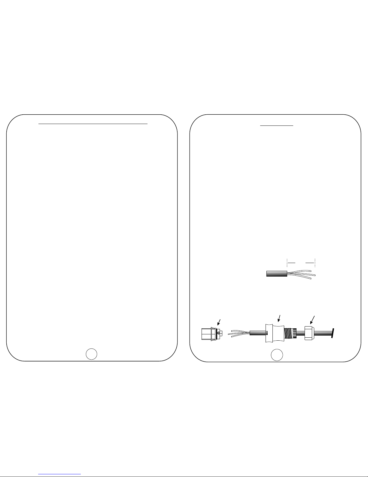
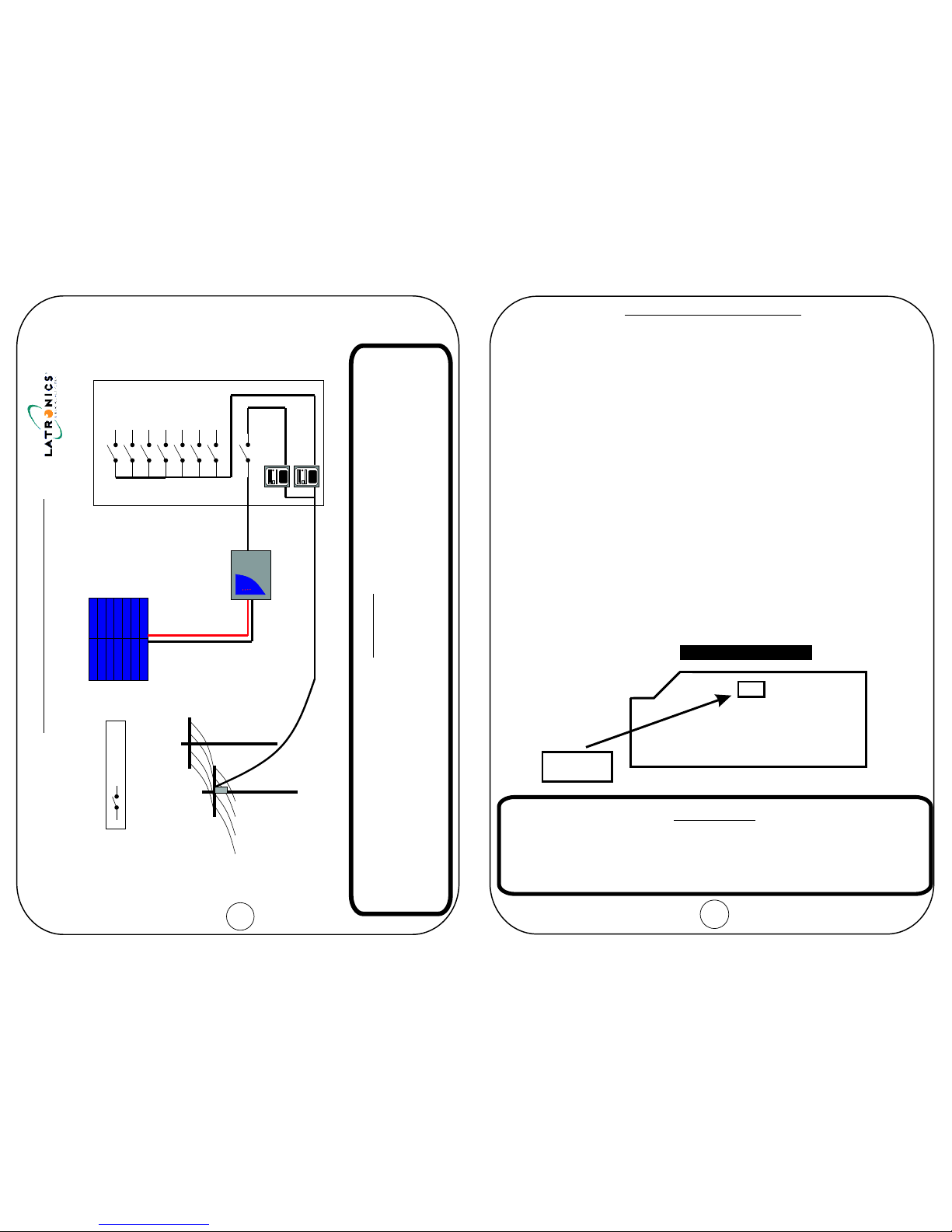
The unit is supplied with both male and female 20Amp Wieland Gesis
lockable AC connectors that
To install connectors read the following procedure.
1. Make sure Inverter is switched OFF before working on mains wiring. Turn
external AC Circuit Breaker switch into OFF position and
make sure it cannot be switched back on.
2. Test the wiring with a voltmeter to make sure no voltage is present.
3. Peel back 30mm of cable jacket and cut Active and Neutral cables
5mm shorter than Earth.
4. Strip 5mm off all three cables.
5. Take the Wieland Gesis connector, disassemble into three main sections
and insert stripped wire through as shown below.
E
can be disconnected under full load and
complies with AS4777 standards for an isolator at the inverter.
MEN
30mm
Earth
Pressure Ring
Main Body
Socket
Round 2.5sqmm Twin & Earth Cable
RADIO FREQUENCY INTERFERENCE
Radio Frequency Interference (RFI) is a phenomenon that exists in modern
society and is a problem in many areas of electronics. For Inverter users,
RFI normally presents itself in the form of static and/or interference when
listening to an AM radio and in unusual cases may interfere with TV reception.
Over the years Latronics has continued to invest significant time and effort in
the reduction of RFI related emissions from the entire product range, so that
they comply with the appropriate International and/or Australian Standards.
Even with this compliance, there are situations where RFI may still be a cause
for concern, and can differ greatly from installation to installation. Accordingly,
the following is a list of recommendations made to assist in the overall
reduction of RFI.
1. Avoid running DC and AC cables in the
same conduits and/or cable trenches. It is strongly recommended that
DC and AC wiring be separated by the greatest distance possible. In
extreme cases, the use of shielded conduit may be necessary.
2. . DC cables can act as an aerial,
therefore all such cables should be kept as short as is practicable. For
best performance minimize DC cable length to Inverter and Batteries and
if possible avoid the use of auxiliary DC loads.
3. . For household installations, it is recommended that a
“good” Earth Stake is located as nearby the Inverter as is possible.
4. These types of radio equipment inherently suffer
from all forms of RFI, especially when the received signal level is weak.
In such cases reception can sometimes be improved by relocation of the
radio itself, alternatively the use of an appropriate external antenna and
co-axial cable may be necessary. External antennas should be located
in a manner that ensures maximum signal strength whilst affording the
greatest possible distance away from the Inverter and Batteries.
5. TV signals are transmitted as FM waveforms. This type of
signal fundamentally reduces the effects of RFI, therefore the use of a
good antenna and feeder cable is normally sufficient to ensure quality
reception. Locating the television as far as possible from the Inverter may
also improve picture clarity.
Separate DC and AC wiring.
Minimize length of DC cabling
240Vac Earth
AM and HF Radios.
Televisions.
16 5

6. Connect the Active, Neutral and Earth cables as per diagram below.
7. Push the socket back into the Main Body until it clips in.
8. Screw the Pressure Ring back in to form a tight seal.
9. Plug into PV Edge.
To disconnect the plug, simply push the clip in and unplug.
Note: The clip section can be completely taken out if a lockable connector
is not desired.
NL
E
Neutral Active
Earth
Socket
15
FAULT FINDING
HELPFUL HINTS
Should the Inverter appear to be malfunctioning we suggest the following to
eliminate any external problems.
Turn the Inverter OFF by switching the DC & external AC Circuit
Breakers OFF. Leave OFF for 60 seconds.
Reconnect the DC Solar Input by switching DC breaker ON. All lights
on the Inverter should come ON for 1 second at power up and then go
OFF. The 75% light should remain ON to indicate the Solar Input is
available. Solar Input voltage needs to be above the automatic turn ON
voltage, see pg 18, for the light to turn ON. If the light does not
illuminate check Solar Input for correct operation.
Next reconnect the AC grid by switching the external AC breaker ON.
After 20 seconds the 75% light should begin flashing to indicate Inverter
reconnecting to the AC grid. The light will flash for 60 seconds while the
PV Edge checks that the mains voltage and frequency are stable.
Should the light not begin flashing check if the AC grid is present.
After the 75% light stops flashing the Inverter will begin feeding power
into the AC Grid.
!
!
!
!
!
!
!
!
Make certain that you understand the operation of the Inverter.
Remember that it has automatic reconnection to the AC grid.
Make sure leads and terminals are not corroded, loose or faulty in any
way.
Make sure Circuit Breakers or switches are reset properly. If unsure
switch OFF and ON again.
6
Push to release

7
Battery Back-Up System
10A
Legend
PV Edge
LS Inverter
Solar Panels
AC Transfer Switch
(ACTS-2)
Regulator
(Optional)
Switchboard
Power
Power
Lights
Lights
Hot Water
Stove
PV Edge
Air Con
(Example only)
Main Switch
PVE1200 – 48V (min 200Ahrs)
PVE2500 – 96V (min 200Ahrs)
Batteries
= Circuit Breaker
AC
DC
10A
Export Meter
Import Meter
Grid Mains
14
Note 1:
Note 2
The DC input is suitable for connection to solar modules
only, when MPPT is enabled.
: Do not exceed recommended Maximum DC Input Power.
Note 3: All solar modules should be of the same type and brand.
Therefore the maximum power point and voltage variation with
temperature are consistent for all modules, which will ensure
maximum system output.
SOLAR INPUT CONFIGURATION
Panel Power
At 25 C
o
75W
90W
100W
125W
140W
150W
165W
175W
Module
Type
12V
12V
12V
12V
24V
24V
24V
24V
Number of Panels
Per String
4
4
4
4
2
2
2
2
Solar Input
Power
1200W
1080W
1200W
1000W
1120W
1200W
1320W
1400W
No. of Strings
4
3
3
2
4
4
4
4
PVE 1200 (Max Solar Input: 1400Wp)
PVE 2500 (Max Solar Input: 2800Wp)
Panel Power
At 25 C
o
90W
100W
110W
125W
140W
150W
160W
165W
175W
Module
Type
12V
12V
12V
12V
24V
24V
24V
24V
24V
Number of Panels
Per String
8
8
8
8
4
4
4
4
4
Solar Input
Power
2160W
2400W
2640W
2000W
2240W
2400W
2560W
1980W
2800W
Number
of Strings
3
3
3
2
4
4
4
3
4

8
Standard Grid Connect System
WARNING:
The Inverter output is connected to mains electricity, thus it is important that all AC wiring complies
with the requirements of the relevant wiring standards, (AS3000, AS4777).
Any work carried out on AC/Mains wiring is to be performed by Qualified And Licensed
personnel only.
PV Edge
Solar Panels
Grid Mains
Switchboard
Power
Power
Lights
Lights
Hot Water
Stove
Air Con
(Example only)
10A
Legend
= Circuit Breaker
Export Meter
Import Meter
DIP SWITCH SETTINGS
Switch 1 -MPPT / Battery mode
Switch 2 - 50/60 Hz
Switch 4
Switch 5
Switch 6
In the ON position the Maximum Power Point Tracking is enabled.
This is required when the DC input is Photovoltaic Solar Modules only.
In the OFF position the Maximum Power Point Tracking is disabled and the
voltage tracking will operate at a fixed voltage of 54V (PVE1200) or 108V
(PVE2500). This setting is required in a system where a 48V (PVE1200) or
96V (PVE2500) Battery Bank is required on the DC input.
In the ON position the Inverter is set for 60Hz operation.
In the OFF position the Inverter is set for 50Hz operation.
Must be in OFF position for normal operation. The ON position is
a factory AC test setting.
Must be in the OFF position for normal operation. The ON position
is a factory DC test setting.
Not used.
(default)
(default)
(default)
(default)
(default)
Switch 3
Battery type selector not used if switch 1 is ON.
ON = Gel/SLA battery.
OFF = Flooded battery.
13
DIP SWITCH LOCATION
MAIN PCB
DIP Switch located on Main PCB
1 2 3 4 5 6
OFF
ON
WARNING:
Due to dangerous voltages existing inside the unit, make sure
the DC circuit breaker and AC solar isolator are turned off
before opening the unit. Only are
permitted to adjust these settings.
qualified Trades Persons

12
SPECIAL FEATURES
Circuit Breakers
Digital KwH Meter
Night Time Disconnect
Parallel Operation
Note:
Maximum Power Point Tracking
Protection
Maintenance Cycle
There is one double pole DC circuit breaker isolating both DC positive & DC
negative.
The KwH meter shows an accumulative reading of the total power generated
and allows the user to monitor their green power production. LCD display
with 5 digits and 2 decimal places (i.e. 99999.99kwh).
After dark when the solar input is no longer available the Inverter will
automatically disconnect from the AC grid. This feature ensures that during
the night, the Inverter cannot consume any power whatsoever while
remaining idle. Upon sunrise the next morning when solar input becomes
available again, the PV edge will automatically reconnect to the AC grid and
begin generating power.
The PV edge automatically synchronizes to the AC grid, therefore the output
of multiple units can all be connected together, and they will all be
synchronized by the AC grid.
The optimum power level from the solar input depends on the available solar
modules. Even in cloudy weather with fluctuations in the solar radiation
level, the PV Edge constantly monitors and tracks the optimum operating
point to ensure maximum power from the solar modules is achieved.
The AC grid supply is constantly monitored for under and over voltage, over
and under frequency, and anti islanding conditions via active phase shifts.
The DC input is protected against over voltage, reverse polarity and over
current via very fast current limit control. Isolation between the DC input and
AC output is achieved via the Toroidal Transformer. The temperature of the
transformer and switching devices are continuously monitored. The Inverter
is fitted with a cooling fan, which is temperature controlled and only operates
when required.
When in Battery mode ( MPPT disabled) a maintenance cycle is performed
every 30 days. This is a short boost cycle for sealed batteries or an equalize
charge for flooded cells. In this mode the bottom LED will flash slowly until
the cycle is completed.
The Solar inputs of multiple unit Inverters are not to be paralleled.
9
PV Edge
Grid Inverter
Turbine
Controller
Turbine
3-Phase Rectifier
(May be built into turbine)
Batteryless Turbine
Grid Mains
The Latronics Turbine Controller utilizes the latest in micro-controller design to deliver a
stable and safe supply of power to the grid connect inverter. Designed specifically to
integrate with the PV Edge line of Latronics inverters, it allows battery-less grid
connection of wind and water turbines.
NOTE: PV Edge must be in Battery Mode. (See pg 13)

10 11
MC4 Solar Connector
For easy connection and
disconnection of DC Input
Power from Solar Panels or
Battery Bank.
Fan
If the temperature inside the
Inverter reaches preset levels, the
variable speed fan will switch on
initially in low speed and then into
higher speed if the temperature
continues to increase. Obstruction
of the air intake and output will
reduce the power rating of the
Inverter.
Circuit Breakers
ON - OFF switch
DC Circuit Breakers &
kWh Meter
Plug & Play AC
Connector
For easy connection and
disconnection to AC grid.
INVERTER OPERATION
When the Inverter is switched on all 4 LED'S light up for 1 second while the
microprocessor performs a start up and system check procedure.
100% Light (Overload)
This light illuminates when the power level
is between 75% - 100%. This light also
indicates overtemp/overload. In this mode
the lower lights will be OFF and this light
will flash.
75% Light (AC Grid)
This light will be ON when the power level is
between 50% -75%.
This light also has 2 other modes of
operation.
When in either of these 2 modes the bottom
light will be OFF.
This light will be ON when the solar input is
present and the AC grid is disconnected
and/or awaiting reconnection.
This light will FLASH for 90 seconds when
the inverter initially connects to the AC grid
and performs a voltage and frequency
stability check before feeding power into the
AC grid.
50% Light (AC Fault)
This light will be ON when the power level
is between 25% - 50%. When an AC fault
is present this light will FLASH and the
bottom light will be OFF.
25% Light
This light will be ON when the power level
is between 0% - 25% or it will flash during
a battery maintenance cycle (see pg12).
Indicator Lamps
The 4 lights on the front panel indicate the
Inverter power level in increments of 25%
LED 4 -100% (top Led).
LED 3 - 75%.
LED 2 - 50%.
LED 1 - 25%. (Bottom Led).
If the Inverter were supplying 60% of
Full power then Led’s 1, 2 & 3 would be illuminated.
Table of contents
Other Latronics Inverter manuals
Popular Inverter manuals by other brands

Hitachi
Hitachi WJ200 Series Software Quick reference guide

Huawei
Huawei iSitePower-M ISP-M-MAB05B1 manual

Delios
Delios DLS 300C installation guide

PAW
PAW SolarBloC midi 2D Installation and commissioning instructions

Troy-Bilt
Troy-Bilt 5500 Watt quick start guide

Saftronics
Saftronics CIMR-VG5U Installation & Quick Start Manual