Latronics LS-2012 User manual

LS SERIES II INVERTER
Latronics LS Series MK2 Sinewave Inverter Manual
Before installation or use please read through this manual
Instruction Manual
English
Helios Power Solutions , 3 Heremai St, Auckland, NZ- Ph : +64 9 8350700 - Email: [email protected] - www.heliosps.co.nz

WELCOME
WARNING
Latronics products are all proudly designed, engineered and manufactured in Australia. As a
specialist sinewave inverter company we produce inverters for a diverse range of applications
such as; mining, railways, telecommunications, marine, remote power, motor homes, and other
industrial or commercial installations.
All products are engineered using the latest high quality components and manufactured to
stringent quality standards, thus ensuring Latronics customers all enjoy many years of trouble
free operation.
Please remember to register online at http://latronics.com.au/warranty to validate your 3 year
warranty. Please retain your receipt as proof of purchase.
It is important to us at Latronics, that our clients enjoy the maximum benets from our inverters
in a safe and productive environment.
We strongly advise that you read through the next few pages of this manual, which explains all
the modes of operation and relevant safety precautions for your new inverter.
It is important that all wiring in the inverter installation complies with
the relevant wiring standards.
Any work on this inverter must be carried out by a suitably qualied
electrical worker.
2
If your inverter requires service or repair please contact Helios Power Solutions.

CONTENTS
1.
Considerations Before Install .................................................................................. 4
DC Wiring .................................................................................................................... 5
Battery Sizing.............................................................................................................. 5
AC Wiring..................................................................................................................... 6
Other Safety Considerations .................................................................................... 7
INSTALLATION
3
2.
Battery Safety ............................................................................................................ 8
Battery Maintenance ................................................................................................. 9
BATTERY MAINTENANCE AND SAFETY
3.
4.
Specications Table ................................................................................................ 22
Model and Serial Number ...................................................................................... 23
SPECIFICATIONS & SERIAL NUMBER
5.
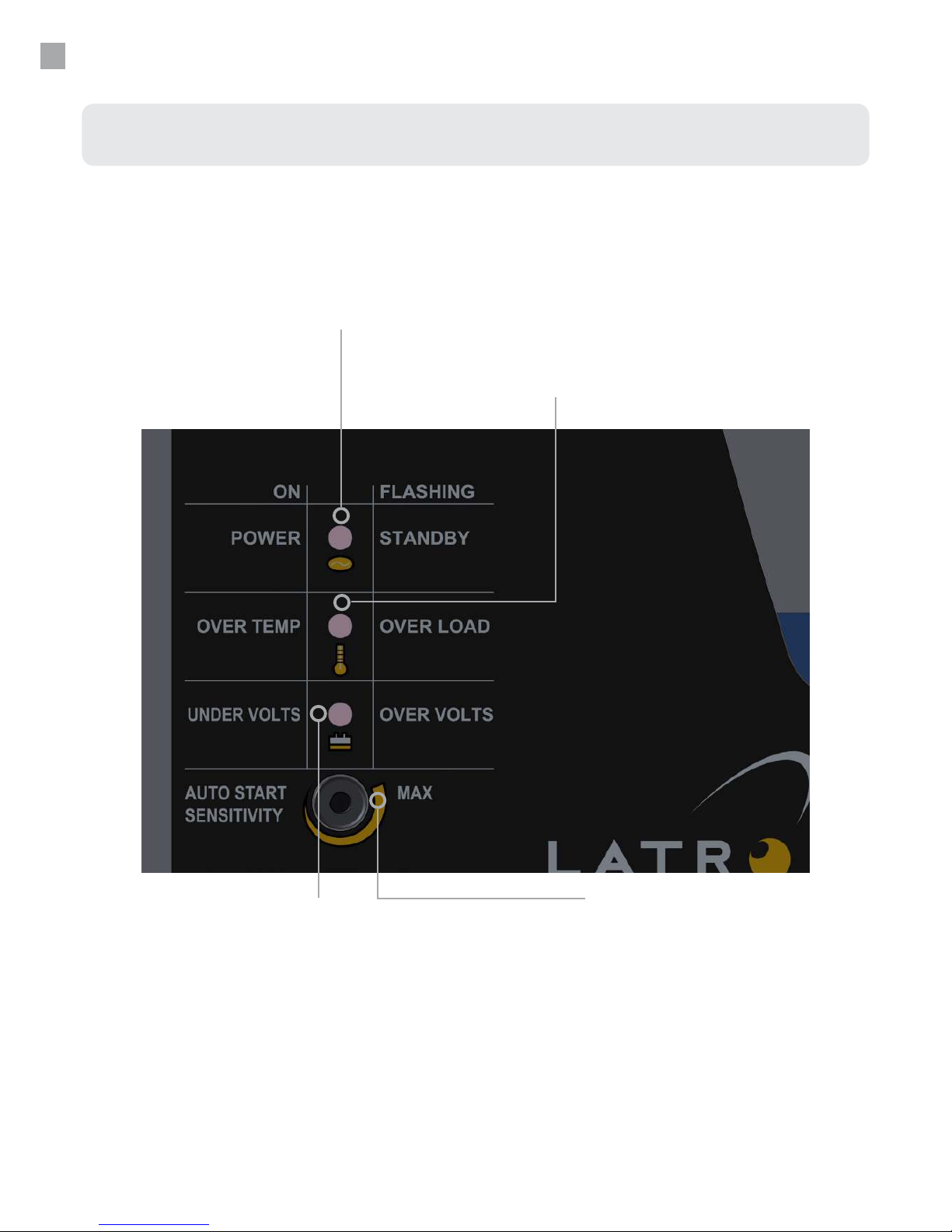
LED Indicators ......................................................................................................... 10
Inverter Features...................................................................................................... 11
Dip Switch Location ................................................................................................. 12
Dip Switch Settings .................................................................................................. 13
INVERTER CONFIGURATION & OPERATION
Part 1 - Warranty Descriptions............................................................................... 14
Part 2 - Returning a Latronics Product for Service Under Warranty ................. 15
Part 3 - General Information .................................................................................. 15
WARRANTY TERMS AND CONDITIONS FOR AUSTRALIA
How to Reduce Radio Frequency Interference .................................................... 16
Inverter Servicing ..................................................................................................... 17
Repair and Decommissioning ................................................................................ 17
Overvoltage Categories........................................................................................... 17
Fault Finding Procedure.......................................................................................... 18
Helpful Hints............................................................................................................. 18
Ineciency and Noise ............................................................................................. 19
Declaration of Conformity ...................................................................................... 20
Customer Notes ....................................................................................................... 21
OTHER ITEMS
6.

●Ensure the inverter has not been damaged in transit.
●The unit has a Pollution Degree of PD3. It is suitable for indoor, unconditioned installation.
●The unit must be placed in a well-ventilated area, not exposed to the open environment, and
free from contaminates (i.e. exhaust gases, sea air, battery gases, dust).
●The LS inverter is of protective class I meaning the case must be earthed. This should be
attached using the earth connection on the a.c. output junction box.
●A space of 10cm is needed on each side of the inverter for adequate transfer of internal heat.
●The inverters inputs and outputs are classied as over voltage category II.
For more information on over voltage category, see page 17
●The inverter can be mounted horizontally on table or oor. The inverter can also be mounted
on a wall, taking note of the sticker being the correct orientation.
●Ensure the mounting surface is structurally sound.
●All fasteners should be rated to carry a minimum of 40kg.
●Inverter must not be:
Installed in direct sunlight.
Mounted on ammable material.
Mounted vertically,
Located such that it can be accidentally touched,
as it can become hot during operation.
INSTALLATION
To install the inverter please follow the instructions on the following pages. If you are unsure of
any aspect of the installation please email or call Latronics.
Considerations Before Install
Slots for easy mounting
Mount two xing to the wall
Slot the inverter on
Fixings and mounting
Ensure at least 3 xings are used at the
top and at least two at the bottom.
4

INSTALLATION
DC Wiring
●The inverter is designed to operate on a battery supply only.
●For best performance, the unit should be placed as close as possible, but not directly on top
of the battery supply.
●The inverter d.c. input voltage is stated on the identication label of the inverter. Check that it
is the same voltage as the battery supply.
●Ensure the inverter is switched OFF before connecting the d.c. supply. Turn the circuit
breaker switch to the OFF position.
●Connect the inverter DIRECTLY to the battery terminals for best performance.
●Input leads marked RED = (positive), & BLACK = (negative).
●The inverter is tted with a circuit breaker in line with the battery positive lead, which can
negate the need for a battery fuse. (Check regulations)
●Maximum input current is limited by inbuilt circuit breaker. Please check nameplate for
rating of circuit breaker.
●Interruption capacity of inbuilt circuit breaker is 4.5kA.
●Ensure you check the short circuit current of the battery bank. If the short circuit current is
more than 4.5kA you must install an appropriately rated external circuit protection device.
OBSERVE POLARITY
Cables connecting the inverter to the battery are designed to achieve
maximum eciency and output power:
DC CABLES SHOULD NOT BE EXTENDED
Battery Sizing
●To ensure peak performance, it is important to choose the right battery for your inverter.
The battery size required will depend on the load and intended running time. Use this
formula as a general guide:
●Recommended battery size= Inverter rating in watts ÷ input voltage × 10
e.g. ( 2000W ÷ 12V ) x 10 = 1666Ah
●Minimum battery size = Inverter rating in watts ÷ input voltage × 3
e.g. ( 2000W ÷ 12V ) x 3 = 500Ah.
●Do not use an undersized battery as this may result in an inverter that does not start or that
will rapidly discharge the battery and may cause damage to the battery.
5

INSTALLATION
AC Wiring
●Make sure the inverter is switched OFF before working on the mains wiring. Turn the circuit
breaker switch into OFF position.
●Ensure that the a.c. wiring is separated from the d.c. wiring to reduce the occurrence of noise
in the installation.
●In standard Latronics inverters the active and neutral of the 240V a.c. output are electrically
isolated from the battery negative, battery positive, and earth connections.
●The inverter a.c. output is connected directly to the transformer output winding.
●Standard Latronics inverters have the a.c. output (active and neutral) oating with respect to
the d.c. and earth. The earth connection is connected to the case only. This conguration
provides the highest level of safety and most exibility for installation wiring.
●The protective earthing connection should be attached to the earth terminal of the a.c.
output junction box.
●When using an inverter with a transfer switch ensure that no highly inductive or capacitive
loads are present such as pumps, compressors or similar. The reason for this is that transfer
from an unsynchronised source can produce large spikes that can feed back onto the
inverter and damage it.
●Ensure that power will never be fed into the inverter a.c. output junction box from
the mains or generator. This would result in the destruction of the unit and will not be
covered by warranty.
●Latronics inverters are suitable for use with type A and type B RCD’s.
●Latronics inverters are suitable for MEN connection.
●The earth is connected internally to the inverter case.
6
WARNING
The inverter output is just as lethal as normal mains electricity.
It is important that all wiring complies with the requirements of the
relevant wiring standards. Any electrical work carried out on a.c./mains
wiring and d.c. wiring is to be performed by suitably qualied electrical
worker.
Systems with solar panels, when exposed to light, supply d.c. voltage.
6

INSTALLATION
Other Safety Considerations
●If the inverter is used in a manner not specied in this manual or by Latronics, protection
provided by this equipment may be impaired
●All standard Latronics inverters have an isolation rating of 3500V between a.c. and d.c. via the
toroidal transformer, which provides safe operation.
●All LS series inverters have short circuit protection which limits the maximum fault current to
the 5 sec. surge rating of the inverter.
●All the switching electronics and control circuitry are on the d.c. input.
●For 12V, 24V and 48V d.c. inverters the circuit breaker assembly isolates the positive pole
only from the battery supply.
●For 72V, 96V and 110V, 120V and 125V d.c. inverters the circuit breaker assembly isolates the
positive and negative pole from the battery supply.
●If the battery voltage drops below nominal voltage this can eect the output voltage. If you
have loads that are sensitive to low a.c. voltages please ensure the battery voltage is never
able to drop below nominal voltage.
●All LS inverters contain double insulated mains frequency transformers.
●There are Y2 capacitors installed across active-earth and neutral-earth and are required for
EMC. These capacitors can establish a voltage divider which shows on some multimeter’s as
a voltage from earth-active and earth-neutral.
7

BATTERY MAINTENANCE AND SAFETY
Battery Safety
●Remove watches, rings, or other metal objects.
●Use tools with insulated handles.
●Wear rubber gloves and rubber soled boots.
●Do not lay tools or metal parts on top of batteries.
●Disconnect charging source prior to connecting or disconnecting battery terminals.
●Determine if battery is inadvertently grounded. If inadvertently grounded, remove the source
from the ground. Contact with any part of a grounded battery can result in electrical shock.
●The likelihood of such shock can be reduced if such grounds are removed during installation
and maintenance.
(Applicable to equipment and remote battery supplies not having a rounded supply circuit)
●When working on batteries protective clothing and eye wear should be worn.
●When replacing batteries, replace with the same type and number of batteries or battery
packs. Consult with the battery manufacturer for more information on replacement.
●CAUTION: Do not dispose of batteries in a re. The batteries may explode.
●CAUTION: Do not open or damage batteries. Released electrolyte is harmful
●If in doubt have the work carried out by a suitably qualied electrical worker.
CAUTION
A battery can present a risk of electric shock and high short-circuit
current. The following precautions should be observed when working on
batteries
8

BATTERY MAINTENANCE AND SAFETY
Battery Maintenance
Battery terminals require frequent care and maintenance. Very high current (up to several
hundred amps), is drawn by the inverter when starting electrical motors and other high
powered appliances. We recommend an inspection of the batteries and the interconnecting
cable connections once every 1-3 months or as recommended by the battery manufacturer.
1. Regularly check all connections; make sure they are always tight. Battery terminals are often
made of soft lead which will slowly compress over time eventually causing loose connections.
2. Check all connections are free of corrosion. Remove any corrosion and coat the terminals
with vaseline or grease to help prevent future corrosion.
3. Take specic gravity or SG readings of each cell using a hydrometer to check the level and
performance of each battery. Alternatively a battery voltage reading for each cell will suce
but may not be accurate for multiple batteries connected in parallel. Report any serious
imbalance to your system installer or battery supplier for corrective action.
9

INVERTER OPERATION
LED Indicators
Standby/Power (Green LED)
This LED ashes when in standby mode
(i.e. no loads connected). When a load is
applied the LED will illuminate continuously to
indicate that 240V a.c. is being supplied.
Over temp/Over load (Red LED)
If the internal temperature exceeds safe operating limits of
the components for more than ve seconds, the inverter
will shut down in over temp with this LED on continuously.
Turn the ON/OFF switch o and allow 5 minutes for the
inverter to cool, then turn it back on. If the applied load
demands more current than the inverter can safely supply
for more than 5 seconds, the inverter will shutdown in over
load and this LED will ash.
Auto Start Sensitivity Adjustment
The screwdriver adjustment slot permits the operator to
adjust sensitivity between 0- 20W. Due to lengthy 240V a.c.
cables the inverter may sense fake loads. To combat this,
turn the control clockwise. Alternatively turning the control
in the opposite direction increases sensitivity. Turning the
control fully anti-clockwise will disable the auto start feature
and the inverter will remain constantly ON.
Undervolts/Overvolts (Red LED)
In order to protect the battery the inverter will
shutdown after 5 seconds if the battery voltage
falls below its limit, (undervolts), or exceeds
the maximum, (overvolts), as specied in the
specications table on page 22. For undervolts
the LED will remain on continuous, while for an
overvolts situation the LED will continue to ash.
10

INVERTER OPERATION
Inverter Features
Circuit Breaker ON/OFF Switch
The circuit breaker is designed for ease of operation and safety. By pushing
the switch “UP”, the battery supply is connected to the inverter. The circuit
breaker will turn OFF automatically if too large a load is left on the inverter
continuously. Reset the switch after allowing approximately 5 minutes to cool.
If the inverter shuts down due to over load, under volts or over volts it can be
reset by turning the circuit breaker OFF, waiting 10 seconds (or until LED goes
out), then turning it on again.
Fan
If the temperature inside the inverter reaches preset levels,
the dual speed fan will switch on initially in low speed
and then into high speed if the temperature continues
to increase. Obstruction of the air intake and output will
reduce the power rating of the inverter.
3 Terminal Input Junction Box
For connection of a.c. input power e.g. from
generator.
(Available only on KX model inverters).
3 Terminal
Output Junction Box
For distribution of
output power
Battery
Leads
Black = Negative
RED = Positive
11

INVERTER CONFIGURATION
Dip Switch Location
WARNING
Due to dangerous voltages existing inside the unit, make sure the
circuit breaker switch is turned o before opening the unit. Should you
have any doubt about performing these modications, we strongly
recommend the use of a suitably qualied electrical worker.
12

INVERTER CONFIGURATION
Dip Switch Settings
In order to access these options you have to open the inverter. Before altering the settings
switch inverter OFF, adjust the setting and switch inverter back ON again. We recommend these
adjustments be carried out by a suitably qualied electrical worker.
SW1 50/60 Hz
ON = 50Hz (factory setting) OFF =60Hz
If you need to operate American or Japanese equipment this option will allow your inverter to
operate at 60Hz. Please note you may also need to change the output voltage to suit equipment.
SW2/SW3 Output Voltage
SW2 OFF & SW3 OFF = 240V a.c. (factory setting)
SW2 OFF & SW3 ON = 230V a.c.
SW2 ON & SW3 OFF = 225V a.c.
SW2 ON & SW3 ON = 220V a.c.
These two switches regulate the output voltage, please keep in mind these values are ±4%
SW4 Automatic Reset
OFF=Disabled ON=Enabled (factory setting)
This feature is designed to restart the inverter and maintain power in the event of an external
fault. Should the inverter shut down due to under voltage, over temperature or any fault
condition it will attempt to reset every 8 minutes until the fault condition clears and normal
operation resumes.
For over load shutdown the inverter will only attempt 5 restarts. If the inverter can not resume
normal operation within 5 restarts, it will remain OFF until reset manually. This prevents
continuous re-application of power to faulty appliances or wiring.
SW5 & SW6 Under Voltage Settings
SW5 OFF & SW6 OFF= (Factory setting)
For under voltage shutdown the inverter will restart when the battery voltage reaches the
reconnect value as shown in the table below.
SETTING 12V VALUE 24V VALUE 48V VALUE
SW5 SW6 DISCONNECT RECONNECT DISCONNECT RECONNECT DISCONNECT RECONNECT
ON ON 10.0 12.0 20 24 40 48
OFF OFF 10.5 12.5 21 25 42 50
ON OFF 11 13.0 22 26 44 52
OFF ON 11.5 13.5 23 27 46 54
13

WARRANTY TERMS AND CONDITIONS FOR AUSTRALIA
Latronic Sunpower Pty Ltd (“Latronics”) provides the original purchaser of a Latronics product
(“You”) with the following limited warranties as set out in this warranty certicate, in addition to
your rights and remedies under consumer law.
The limited warranty periods of this inverter is 3 years. In all circumstances Latronics products
are guaranteed from the date of purchase.
Part 1 - Warranty Descriptions
Latronics warrants to You that our products are guaranteed against defects in material or workmanship, when in
normal use and service.
What you must do:
1. For a limited warranty to apply the registration warranty must be validly completed online at
http://latronics.com.au/warranty by You, prior to the expiration of 3 months from the date of purchase.
2. You must provide proof of purchase.
3. Latronics recommends You keep your receipt as proof of purchase, should any diculties arise concerning
registration of your warranty.
Exclusions:
For the avoidance of doubt, the Latronics product warranties provided herein do not cover damage, malfunctions
or service failures caused by, amongst other things:
• Unauthorized opening of the products, repair, alteration or substitution of nonstandard parts.
• Incorrect design and/or installation of ‘balance of system’.
• Acts of god, accident or similar cause.
• Failure to follow Latronics installation, operation or maintenance instructions.
• Abuse, misuse or negligent acts.
• Power surges, lightning, re, ood, pest damage, accidental breakage, actions of third parties and other
events or accidents outside Latronics’ reasonable control and not arising from normal operating conditions.
• Suitably qualied personnel not carrying out all a.c. and d.c. permanent wiring in accordance with relevant
wiring rules.
Products supplied by Latronics, or Latronics agents are supplied under the express condition that no responsibility
is implied or accepted by Latronics for any damage to any appliance, equipment or property used in combination
with the correct operation of a Latronics product.
All conditions and warranties expressed or implied by statute, common law, equity, trade, custom, usage, or
otherwise howsoever are hereby expressly excluded to the maximum extent permitted by law. Where so permitted,
the liability of Latronics for a breach of condition or warranty that cannot be excluded is limited (at Latronics option)
to the replacement or repair of the goods or of acquiring equivalent goods or the cost of replacing or repairing the
goods or of acquiring equivalent goods.
Latronics does not undertake any commitment to guarantee continuity of supply in the case of obsolescence.
In addition, Latronics reserves the rights to change its standard product range or specication of any model
subsequently without notice and no liability as a result of these occurrences will be accepted.
14

WARRANTY TERMS AND CONDITIONS FOR AUSTRALIA
Part 2 - Returning a Latronics product for service under warranty.
If service is required contact your local supplier/installer or place of purchase for advice before following the below
steps. To claim under warranty:
1. You should contact Latronics customer care centre on 07 5491 6988 or complete the online service form at
http://latronics.com.au/support.
Product model number and serial number need to be readily available to enable prompt processing.
2. If, after investigation, the customer care centre determines the product is or may be defective in material or
workmanship and within the warranty period, they will issue instructions on how to proceed with return and
shipping to Latronics.
3. When packaging a Latronics product for return, appropriate measures must be taken by You to ensure the
products are safely packed for transit. Products damaged in transit due to inadequate packaging will be void of
warranty.
4. A Return Merchandise Authorisation (RMA) form with a valid RMA number must be completed and accompany
products being returned.
5. If, as a result of further investigation by or on behalf of Latronics, such a defect is conrmed, then Latronics must,
at its sole election, either repair or replace your Latronics product. Latronics will also, at their discretion, determine
the most appropriate means to return any warranty repairs (or replacements) to You in a timely manner.
Part 3 - General Information
Replacement of any part or labour involved in repairs will not have the eect of extending the original period of the
limited warranty of the goods. Any faulty part replaced under limited warranty becomes the property of Latronics
for purpose of examination and claim under proprietary warranty.
Under these product warranties, Latronics is not responsible for and You hereby agree to bear any costs associated
with removal, transportation, reinstallation of your Latronics products or any peripheral components in the balance
of any system used in conjunction with Latronics products.
Products returned to Latronics without prior authorisation will be returned to the sender at their expense.
All warranty repairs are completed ex-factory to ensure:
• Fast service turn around time.
• Specialised, factory trained technicians.
• All required components are available (except in the case of obsolescence).
• Thorough testing to all Latronics specications.
• Dedicated test equipment.
• Upgrades/updates to latest Latronics standards/specications (where applicable).
Our goods come with guarantees that cannot be excluded under the Australian Consumer Law. You are entitled
to a replacement or refund for a major failure and compensation for any other reasonably foreseeable loss or
damage. You are also entitled to have the goods repaired or replaced if the goods fail to be of acceptable quality
and the failure does not amount to a major failure.
15

OTHER ITEMS
Radio Frequency Interference (RFI) is a phenomenon that exists in modern society in many
areas of electronics. For inverter users, RFI normally presents itself in the form of static and/
or interference when listening to an AM radio and in unusual cases may interfere with TV
reception. In order to comply with the appropriate International and/or Australian standards,
Latronics has continued to invest signicant time and eort into the reduction of RFI related
emissions from the entire product range.
However with this compliance, there are situations where RFI may still be a cause for concern,
and can dier greatly from installation to installation. Accordingly, the following is a list of
recommendations made to assist in the overall reduction of RFI.
How to reduce Radio Frequency Interference
●Separate d.c. and a.c. wiring: Avoid running d.c. and a.c. cables in the same conduits and/
or cable trenches. It is strongly recommended that d.c. and a.c. wiring be separated by the
greatest distance possible. In extreme cases, the use of shielded conduit may be necessary.
●Minimize length of d.c. cabling: d.c. cables can act as an aerial, therefore all such cables
should be kept as short as practicable. For best performance minimize d.c. cable length to
inverter and batteries and if possible avoid the use of auxiliary d.c. loads.
●240V a.c. earth: For household installations, it is recommended that a “good” earth stake is
located as nearby the inverter as possible.
●AM and HF Radios: These types of radio equipment inherently suer from all forms of RFI,
especially when the received signal level is weak. In such cases reception can sometimes be
improved by relocation of the radio itself, alternatively the use of an appropriate external
antenna and co-axial cable may be necessary. External antennas should be located in
a manner that ensures maximum signal strength whilst aording the greatest possible
distance away from the inverter and batteries.
●Televisions: TV signals are transmitted as FM waveforms. This type of signal fundamentally
reduces the eects of RFI, therefore the use of a good antenna and feeder cable is normally
sucient to ensure quality reception. Locating the television as far as possible from the
inverter may also improve picture clarity.
16

OTHER ITEMS
If you believe your inverter is not functioning normally, please contact the Latronics service team
on 07 5491 6988 or complete the online service form at http://latronics.com.au/support
When your inverter has reached the end of its life and is no longer working, please return the
inverter back to Latronics for recycling and safe disposal. Over 80% of the LS Series Inverter is
directly recyclable.
The concept of overvoltage categories is applied to each separate circuit in the power
conditioning equipment including mains circuits, PV circuits, and other circuits, whether
connected to or isolated from the mains and PV circuits.
Care should be taken when installing wiring that transients could be induced in conductors and
over voltage suppression devices should be used to protect against such transients.
Inverter Servicing
Overvoltage Categories
17
Repair and Decommissioning
●Check the inverter once a month to ensure it is operating correctly.
●Check that there is no obstructions for correct ventilation.

OTHER ITEMS
Should the inverter appear to be malfunctioning we suggest the following to eliminate any
external problems:
Fault Finding Procedure
1. Turn the inverter “OFF” via the circuit breaker switch on the front panel.
2. Disconnect all a.c. wiring from the inverter.
3. Disconnect d.c. battery leads from battery. Clean all terminals by removing all grease/
corrosion on both d.c. leads and battery terminals.
4. Ensure you have sucient battery capacity at the nominal voltage (specied on the
compliance label of your inverter).
5. Please note: Use minimum 100AH battery or the size of a substantial car battery.
6. Make connection directly to battery terminals and ensure all connections are tight.
7. Remove other wiring from the battery to ensure that the inverter is the ONLY device
connected to the battery bank.
8. Ensure battery voltage is within the correct limits as outlined in the section INVERTER
SPECIFICATIONS on page 22. If you do not have a d.c. voltmeter or multimeter check the
front panel for overvolts and undervolts LED’S.
9. Turn the inverter ON via the circuit breaker switch on the front panel. Observe the lights on
the front left of your inverter. Refer to INVERTER OPERATION on page 10 for explanation of
indicator lights.
10.Plug in various appliances and monitor the inverters operation.
11.If inverter is still not working please contact technical support, details on page 24.
Helpful Hints
●Remember that the inverter automatically starts when a load is applied.
●Make sure leads and terminals are not corroded or faulty in any way.
●Make sure the inverter goes into STANDBY with no load switched on.
●Make sure the circuit breaker is reset properly. If unsure switch OFF and ON again.
●In extreme weather it is suggested to shutdown and disconnect the unit.
18

OTHER ITEMS
Ineciency or Noise
Some appliances may cause the inverter to run ineciently or more noisy than usual due to the
current waveform they draw.
Certain appliances draw un-even load from a.c. supplies which from a mains supply might
be OK. When operating from an inverter however it may unbalance the internal toroidal
transformer which can cause the inverter to overheat or make undue noise. An example of an
un-even current waveform is below
Some appliances that can cause this issue are
●Hair dryers
●Variable heat guns
●Washing machines
●Dish washers
●Air-conditioners
●Microwaves
This imbalance can be evened out by applying more load or trying a dierent model/brand.
Also ensure that the appliance has RCM compliance as uncertied equipment can put
unnecessary noise back into the inverter.
If you are having trouble with a certain appliance please call Latronics for further assistance.
19

OTHER ITEMS
Declaration of Conformity
Manufacturer:
Latronic Sunpower Pty Ltd
105 Grigor Street West
Moat Beach, Queensland
Australia, 4551
I Declare that the LS series of inverters conform to the requirements of the following standards
EN61000-6-1
EN61000-6-3
En55014
AS1044
EN60335-1
AS/NZS 3100
IEC 62109-1
IEC 62109-2
And therefore conform to the regulations of the EC directives
Directive 2004/108/CE (EMC directive), Directive 2006/95/CE (low voltage directive)
Date that CE marking was rst axed 2007
Also conforms to the RCM marking regulations for Australian emission standards
All products are manufactured with full traceability in accordance with the quality system
requirements of AS/NZS ISO 9002
Signed
William Pettit
Latronics Chief Engineer
11th Jan 2016
20
This manual suits for next models
7
Table of contents
Other Latronics Inverter manuals
Popular Inverter manuals by other brands

Solectria Renewables
Solectria Renewables PVI 13KW Installation and operation manual

Mitsubishi Electric
Mitsubishi Electric FR-F820-04750 instruction manual

Exide
Exide integra 700 User's manual & warranty card

Wagan
Wagan 2107 owner's manual

Toshiba
Toshiba Tosvert-130 installation manual

SINAMICS
SINAMICS G120 manual