Latronics TG Series User manual

TG Series
owner
manual
new grid
connect
inverter

Latronics®
empowering
Australians
welcome

In order to produce the most reliable products
available, Latronics inverters have been designed
to endure the most rugged terrain and the harshest
conditions across the Australian continent.
All products are engineered using the latest high
quality components and manufactured to stringent
quality standards, ensuring Latronics customers
enjoy years of trouble free operation.
It is important to us that our clients enjoy the maximum
benefits from our inverters in a safe and productive manner.
We strongly advise that you read through this manual which
comprehensively explains all the modes of operation and
relevant safety precautions of the TG Series Inverter.
Latronics products are all proudly designed,
engineered and manufactured in Australia.
As a specialist inverter manufacturer we produce
inverters for a diverse range of applications such as:
residential, mining, railways, telecommunications,
marine, remote power, motor homes and other
industrial or commercial installations.
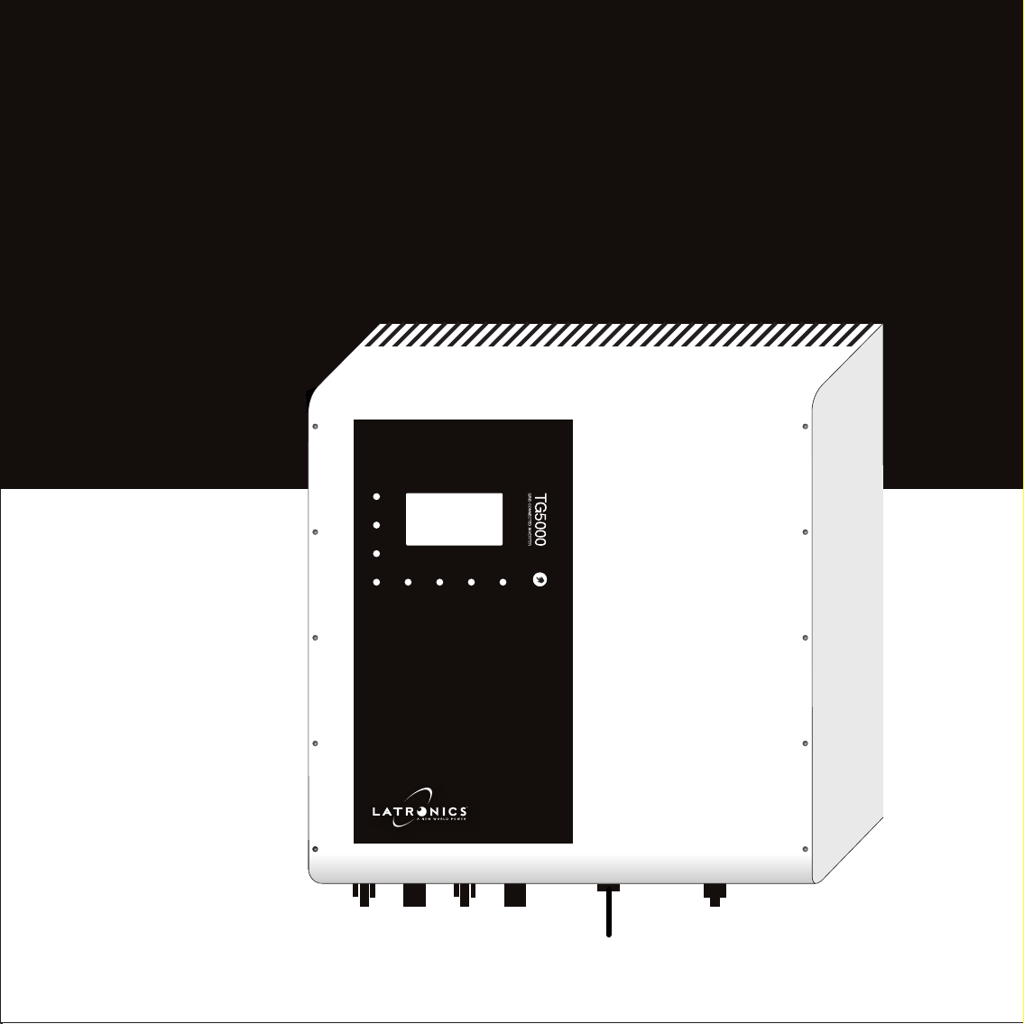
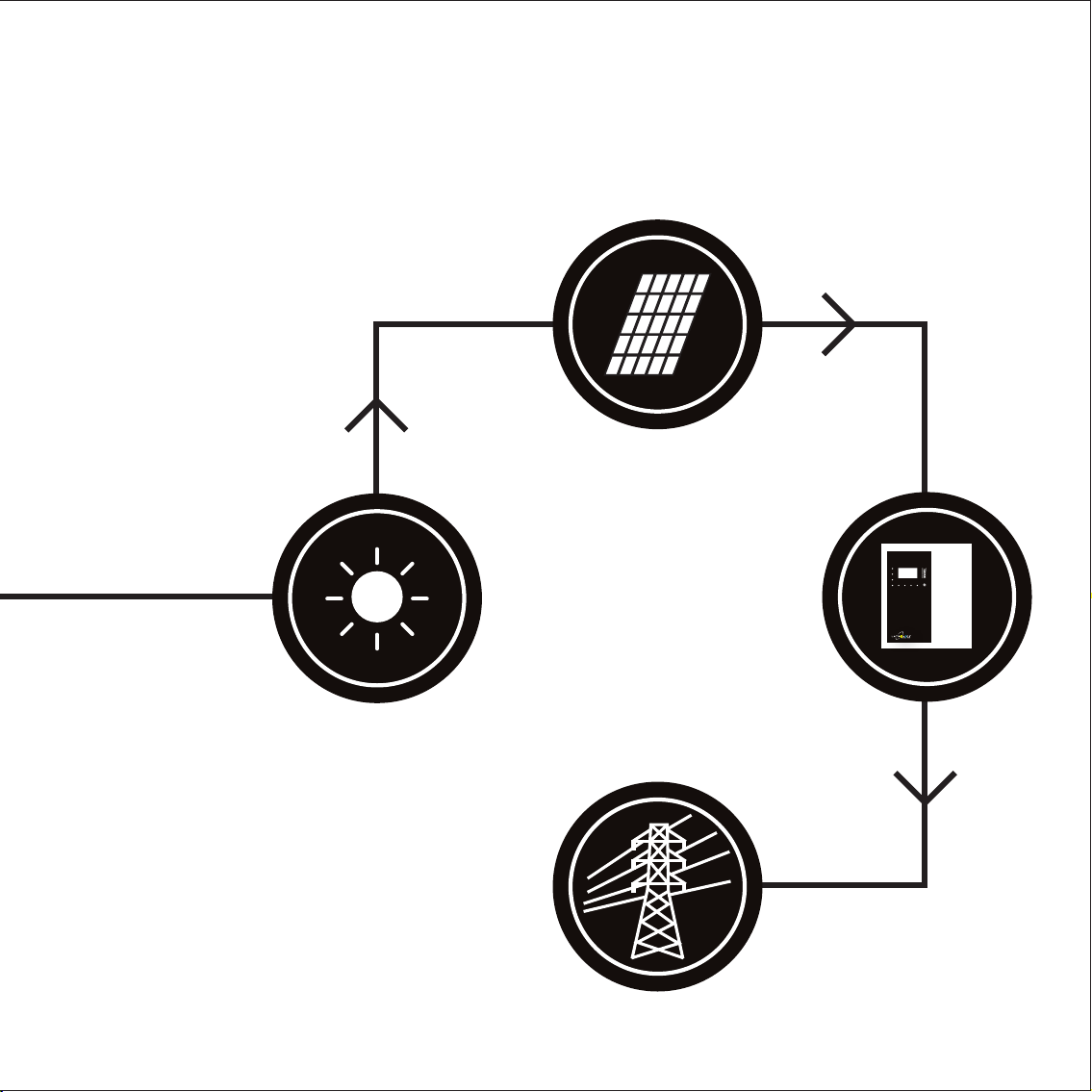
overview of Latronics

contents
TG Series

w
overview of a grid connect system 01
glossary of terms 03
overview of TG Series Inverter 05
LCD and button operation 07
shutdown procedure 09
fault finding 10
technical specifications 11
radio frequency interference 13
faults 15
error messages 16
inverter repair and decommissioning 17
terms and conditions 18
useful websites 21
contact latronics / serial number 22

overview of a
grid connect
system A solar grid connect system is a green way
of offsetting the amount of power the utility
needs to generate to service its customers.
It is usually decentralised and only
operates during daylight hours.
Depending on your local regulations,
the energy generated during these
hours may be used in your house first
or go straight out to the public grid.
01

02

glossary of
terms
03

PV panels
(Photovoltaic Panels) Generate DC power in the
conversion of light through to electrical energy.
Grid connect inverter
Converts DC power to AC power suitable
for feeding into the public utility grid.
LED
(Light Emitting Diode) Energy efficient
lighting and indicator choice.
Wi-Fi
Allows for wireless internet connection
through a wireless router.
LCD
Liquid Crystal Display.
RJ45 connector
Similar to a telephone jack but slightly wider.
Used to connect Ethernet cable.
Solar Array
A group of solar panels. 04

overview of
TG Series
Inverter
05

LCD screen
LED indicators
Multifunction button
DC solar input AC mains connection
06
Wi-Fi antenna

LCD and button
operation
Power Now 4477W
350V
6.4 A
320V
7.1 A
246V
18.2 A
50.0Hz
33degC
07

LCD and button
operation
08
The front LCD is asleep to conserve power
under normal operation. To wake it up press the
multifunction button. This button is used to scroll
through the multiple screens of the inverter.
The main screen shows an overview of your solar system
including solar values, AC grid values, temperature, status
and power as shown on the previous page. The remaining
screens show power generation for the day, week and month.
Please note these values are for informational purposes
only and are not to be used for revenue metering.
The multifunction LEDs are useful for a quick glance indication.
When the inverter is running, the LEDs act as a bar graph
running top to bottom, left to right displaying the amount of
power being generated.
Under other conditions, such as fault
conditions, the LEDs will glow a different
colour depending on the mode i.e. red for
‘error’.
Please check your inverter once a
month to ensure it has not ceased
generation for any reason

shutdown
procedure
In day-to-day operation a grid connected inverter does
not usually need to be shut down or disconnected. In the
event you are required to shut down the inverter please
Isolate the solar panel array
Isolate the mains to the inverter
Isolation of these power sources could be via switches, isolators
or plugs so please follow the ‘shutdown and isolation’ procedure
given to you by your solar installer on original installation.
Removal of the inverter must
be completed by a suitably
qualified person
1
2
09

shutdown
procedure
Turn the inverter OFF by switching the external DC &
external AC isolators OFF. Leave OFF for 60 seconds.
Turn on both inputs and the LCD should then turn on.
After approximately 5 seconds the inverter should
start its ‘grid check’ with the LEDs glowing yellow.
(Please note this step may take up to 60 seconds.)
After 60 seconds the inverter should go online and
start to produce power. If the RED LEDs appear
or you are still having problems then please go
through the error messages on page 16.
fault finding
Should the inverter appear to
be malfunctioning we suggest
the following to eliminate
any external problems
1
2
3
10

Input (DC) TG5000 TG4600
Absolute Max. input voltage 500V
Operating voltage range 120 - 500V
Panel MPP voltage 150 - 400V
Rated input voltage 400V
Start input voltage 150V
Recommended max solar input 6500W | 6000W
Max. input current per channel 15A
Number of independent MPPT inputs 2
MPPT efficiency >99%
Output (AC) TG5000 TG4600
Rated power (@ 230 V, 50 Hz) 4950W | 4600W
Max. AC power 5500W | 5000W
AC nominal voltage / range (adjustable) 230V / 205-265V
AC grid frequency / range (adjustable) 50Hz / 45-55 Hz
Rated grid frequency / rated grid voltage 50 Hz / 230 V
Max. output current 23A | 20A
Power factor at rated power 0.99
Phase Connections Single Phase
THD (%) ≤4%
TG series grid connect
11

Features
DC connection MC4
AC connection Wieland Gesis
Display
Monochrome LCD Graphics
Interface Wi-Fi
Warranty 5 years
General data
Max. efficiency / European efficiency 97.1% / 96.5%
Dimensions (W / H / D) 400 / 450 / 185 mm
Weight 27kg
Ambient temperature range -25°C to 60°C
Self-consumption (at night) <5W
Topology Transformerless
Cooling Concept Convection
TG series grid connect
specifications
12
Specifications and all manual content are subject to change without notice.

radio frequency
interference
Radio Frequency Interference (RFI) is a phenomenon that exists
in modern society in many areas of electronics. For inverter
users, RFI normally presents itself in the form of static and/or
interference when listening to an AM radio and in unusual cases
may interfere with TV reception.
In order to comply with the appropriate International and/or
Australianstandards,Latronicshascontinuedto investsignificant
time and effort into the reduction of RFI related emissions from
the entire product range.
However with this compliance, there are situations where RFI
may still be a cause for concern, and can differ greatly from
installation to installation. Accordingly, the following is a list of
recommendations made to assist in the overall reduction of RFI.
13

radio frequency
interference
Separate DC and AC wiring
Avoid running DC and AC cables in the same conduits and/
or cable trenches. It is strongly recommended that DC and
AC wiring be separated by the greatest distance possible. In
extreme cases, the use of shielded conduit may be necessary.
Minimise length of DC cabling
DC cables can act as an aerial, therefore all such cables should
be kept as short as is practicable. For best performance,
minimise DC cable length to inverter and solar panels.
AM and HF radios
These types of radio equipment inherently suffer from all
forms of RFI, especially when the received signal level is
weak. In such cases, reception can sometimes be improved
by relocation of the radio itself, alternatively the use of an
appropriate external antenna and coaxial cable may be
necessary. External antennas should be located in a manner
that ensures maximum signal strength whilst affording
the greatest possible distance away from the inverter.
Televisions
TV signals are transmitted as FM waveforms. This type of
signal fundamentally reduces the effects of RFI, therefore the
use of a good antenna and feeder cable is normally sufficient
to ensure quality reception. Locating the television as far as
possible from the inverter may also improve picture clarity.
1
2
4
14
3

15
faults
Wi-Fi is not working
Please go through the Wi-Fi connectivity procedure in the supplied
“TG Series connectivity manual” that came with your inverter.
No LCD or LEDs are being displayed
There is no mains supply to the inverter. Please check solar main switch in
your switch board is in the ‘ON’ position. If the switch is on and still no LCD or
LED’s are displayed please call your solar installer for further instructions.
Inverter is displaying red flashing LED’s
Please go through the error messages on the next page for further details.
If you have gone through the fault finding
procedure on page 10 and the unit still
appears to be maulfunctioning, please
see below for further instruction
This manual suits for next models
2
Table of contents
Other Latronics Inverter manuals
Popular Inverter manuals by other brands

Samlexpower
Samlexpower Evolution EVO-4248SP quick start guide

Goodwe
Goodwe HT Series user manual

Steca
Steca stecagrid 300 Installation and operation manual

REFU
REFU REFUsol 48K-UL Installation and operating manual

SunReports
SunReports Apollo2 quick start guide

Crown Micro
Crown Micro XAVIER 3KVA user manual