LAUNCH Tire Changer TWC-481
4
Spacing
The location to install the machine should be in
accordance with safety regulations:
The machine should be installed in a place close
to the main power source and compressed air
system.
Install the machine on smooth concrete surface
or another surface with hard flooring. 4 anchor
bolts can be used to fasten the machine to the
floor to avoid vibration and noise.
Leave enough space for the operation and
maintenance of the machine. The space should
be no less than 1M (39”) in front and on the two
sides of the machine, 0. M (20’) behind it so that
operation on different parts shall not be hindered.
If the machine has to be installed outdoors, a
protective shelter should be built.
Never operate the machine in a place with
flammable gas.
Note:
For safety and proper operation, keep the machine at
least 0.5 (20”)away from any wall.
Power and Air Connections
Before installation, check to verify that the
electrical power and the compressed air sources
are in accordance with the specifications on the
nameplate. Any electrical connection should be
done by the specially trained technician.
The power outlet should be at a place within the
sight of the operator. The height should be
between 24”
67”.
In case the line voltage is not stable, a voltage
stabilizer should be used between power source
and the machine.
The machine should be well grounded.
The tire changer is not equipped with overload
protection. Please connect power according to the
electric diagram included in the User’s manual.
Otherwise, the manufacturer will not be responsible for
any accidents.
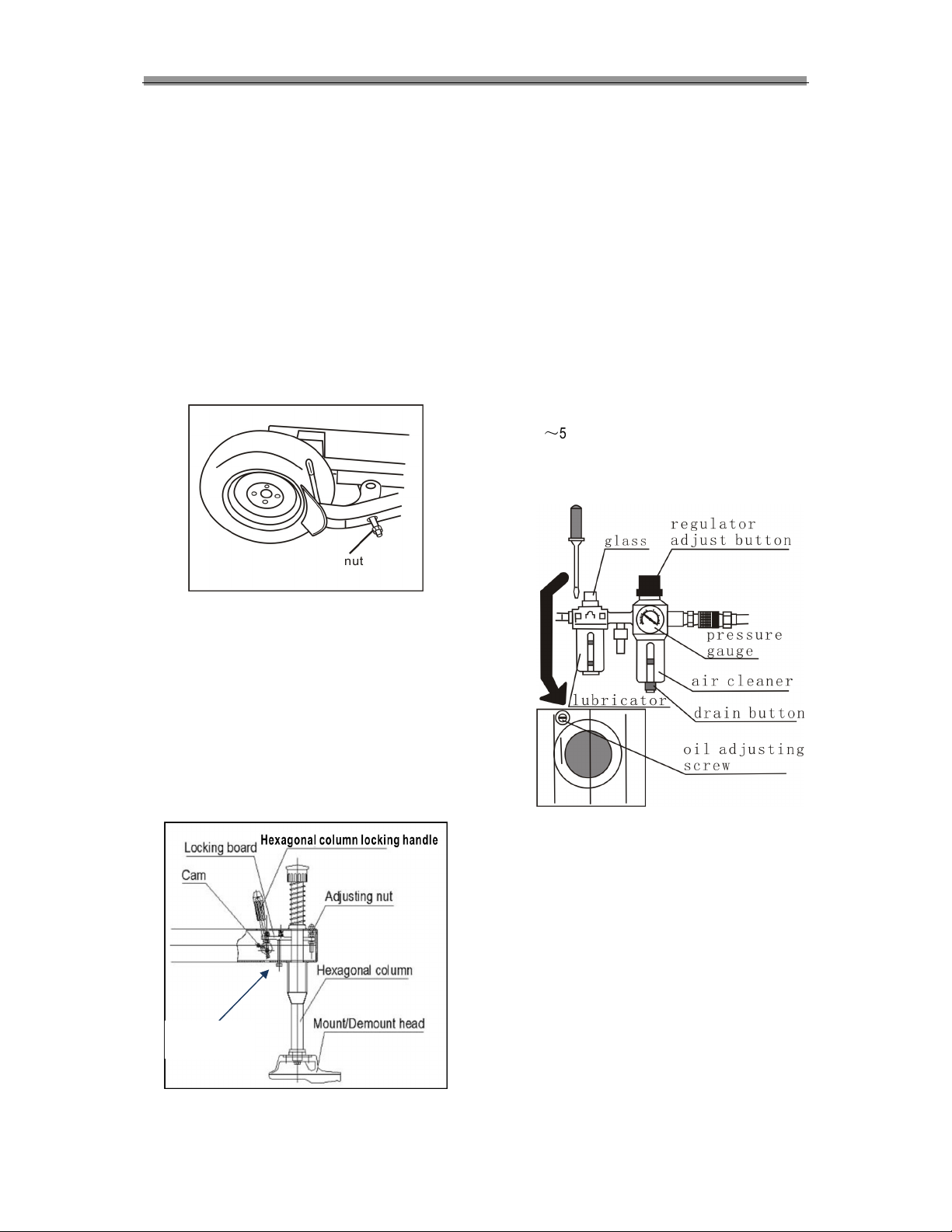
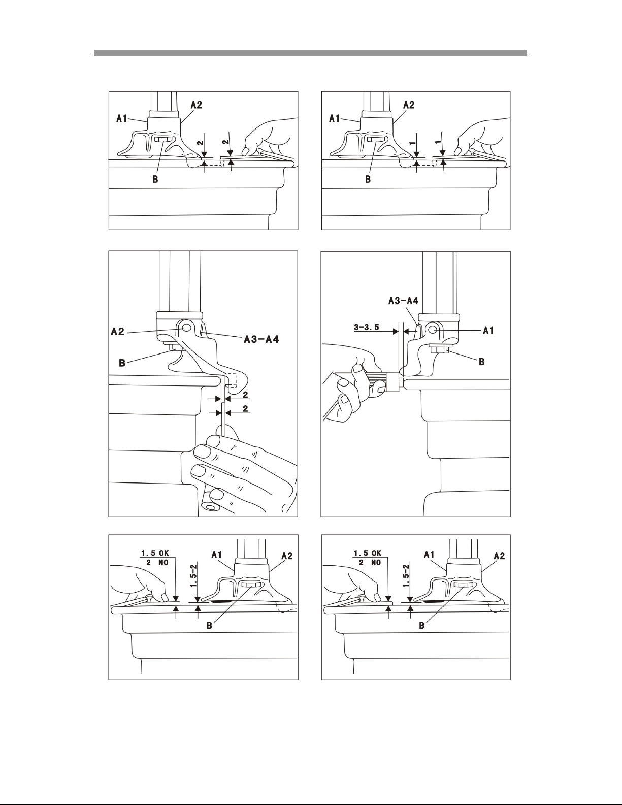
Adjusting
Note:
ake sure that the power, air sources and the oil
level in the oil cup are in accordance with the
requirements.
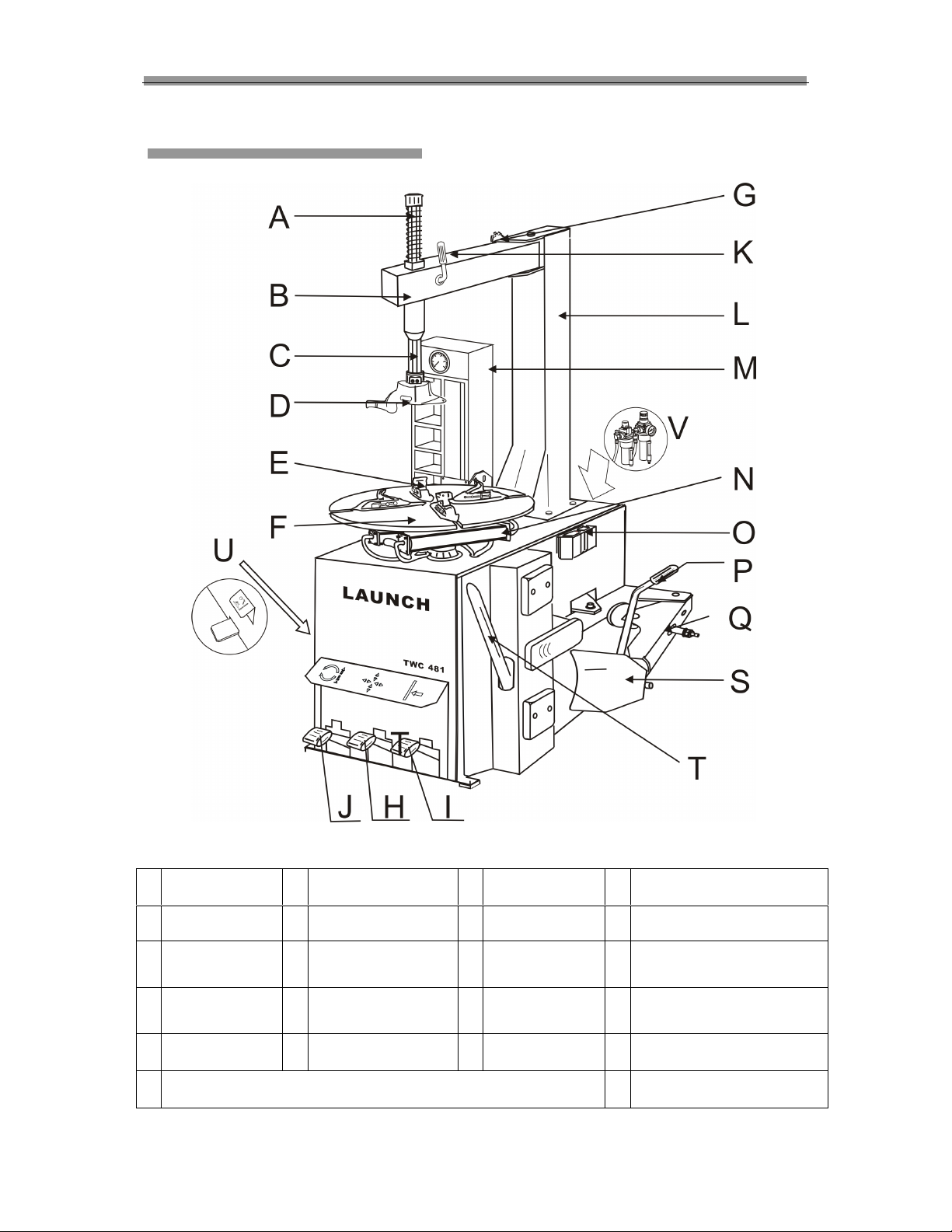
Initial Operation (Fig.05)
Note: The three pedals should be on the initial
position.
Fig.0
Depress pedal (J), turntable (F) will rotate
clockwise;
Lift the pedal (J), turntable (F) will rotate
counter-clockwise;
Depress pedal (I) to move bead breaker (S),
release it to restore;
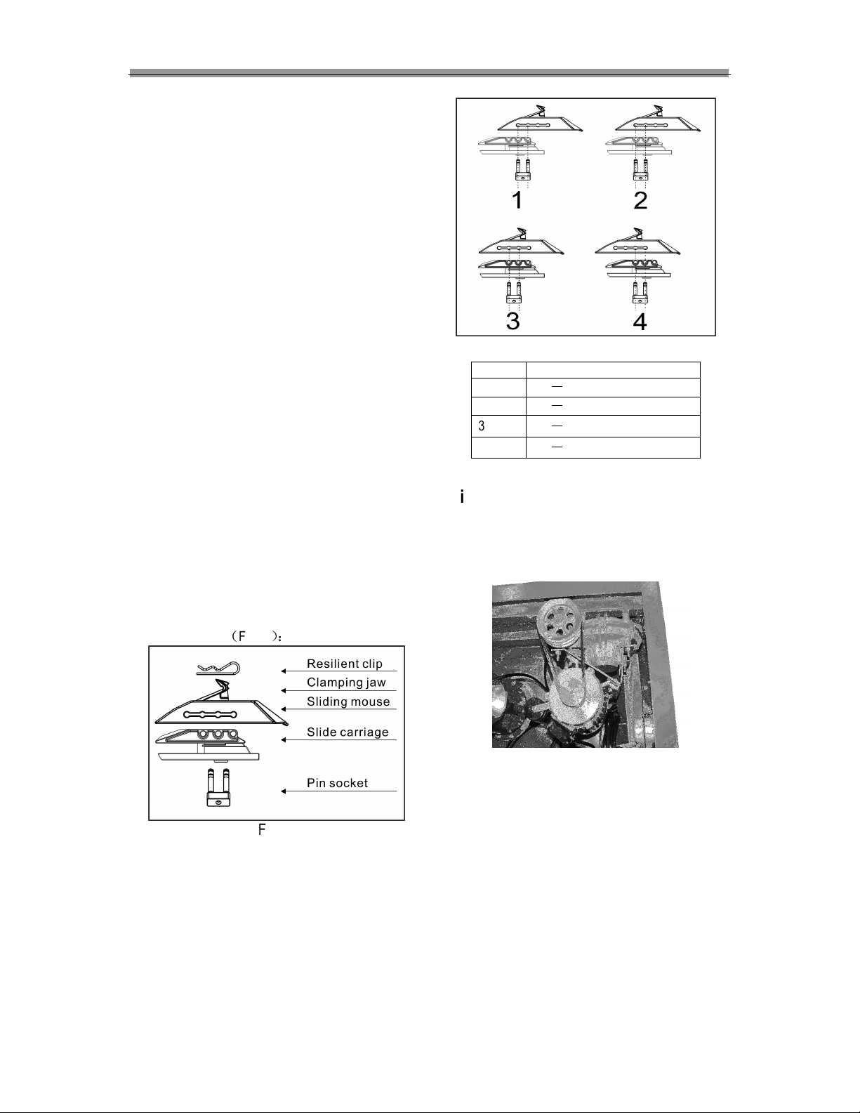
Depress pedal (H), clamp jaw slides (E) on the
turntable will open. Depress it again, the jaw
slides will close;
Rotate the stop screw knob (K) to position the
swing arm;
Press the Hexagonal bar (C) and move the
Hexagonal bar locking handle(B) to lock the
Hexagonal bar;
Loosen the Hexagonal column locking handle
(B) and the Hexagonal column will reset.
When the Inflation pedal U
Fig.01-1
is lightly
pressed, air will expel from the air hose
connected with the inflation gauge (mounted on
tool box). When the pedal is pressed down to
the lowest position, air will quickly blast behind
four jaws (the end of the slides).