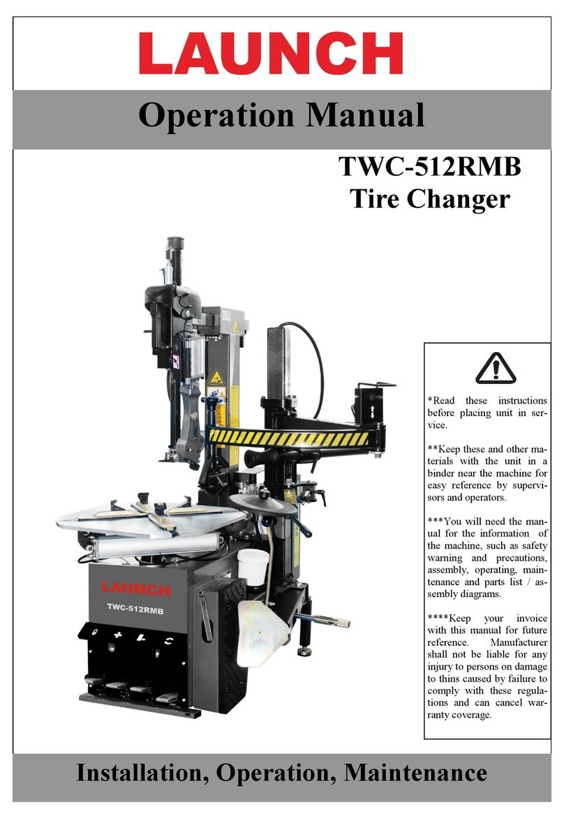
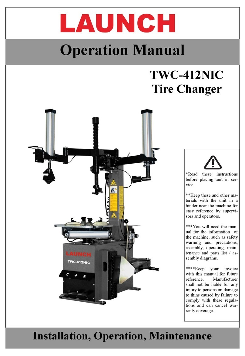
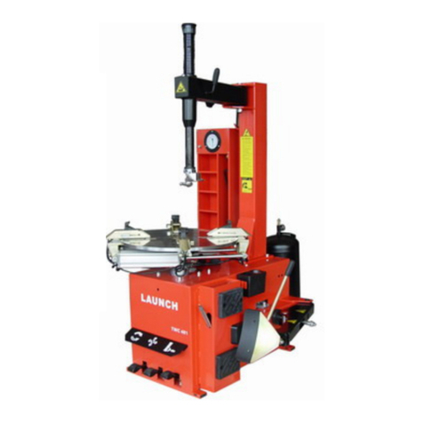
Launch TWC-581 User manual

1
TWC-581
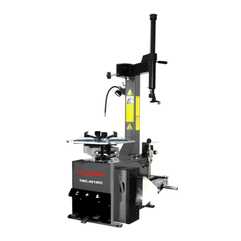
Swing Arm
Tire Changer
Launch Tech USA, INC.
2460 Peck Road
Whittier, CA 90601 USA
1-877-LAUNCH 9 62/463-
1380
62/463-1 90 (FAX)
www.launchtechusa.com
Installation and Parts
Manual

LAUNCH Tire Changer TWC-581
2
Table of Contents
Table of Contents ................................................................................................ 1
Safety Precautions.............................................................................................. 3
Main Structure ................................................................................................. 4
Tools.................................................................................................................. 5
Installation........................................................................................................ 5
Unpacking.................................................................................................. 5
Installation................................................................................................. 5
Installation of Supplementary arm assembly………………………………… 6
Air Connections…………………………………………………………………….7
Installation of Air Tank………………………………………………………….. 7
Transport ................................................................................................... 8
Positioning ................................................................................................. 8
Power and Air Connections....................................................................... 8
Adjusting ................................................................................................... 8
Initial Operation (Fig. 01-1) ...................................................................... 8
Clamping System of the Jaws……………………………………………………9
Dri e system……………………………………………………………………… 9
Bead Breaker……………………………………………………………………… 10
Hexagonal Column Clamping System……………………………………….. 10
Supplementary Arm……………………………………………………………… 10
Air Pressure Regulator, Gauge and Lubricator Assembly………………… 10
Mount / demount Head……………………………………………..………..11
Direction of the switch’s installation……………………………………. 14
Parts List ....................................................................................................... 15
Note: The wearing parts are indicated by *. .................................... 15
Note:........................................................................................................ 23
TWC-581 Circuit Diagram……………………………… 31
TWC-581 Pneumatic Diagram………………………. 32

LAUNCH Tire Changer TWC-581
3
Safety Precautions
This manual is a necessary component of the product. Please review carefully.
Keep the manual for later use when maintaining the machine.
This machine can only be used for the designed purpose. Never use it for any other purpose.
The manufacturer is not held responsible for any damage incurred by improper use or use for the purposes other
than the intended one.
Before installing and adjusting the equipment, pay attention to the following:
Read this manual and all other instructions for the equipment thoroughly. Modification to any components or
parts, or use the machine for other purpose without either obtaining the permission from the manufacturer, or
observing the requirement of the instructions may lead to direct or indirect damage to the equipment.
The installation and adjusting personnel should have a good understanding of electrical devices.
The equipment can only be operated by qualified personnel with special training.
TWC- 81 should be installed on the smooth ground.
Keep the back panel 0.7 M (29”) away from the wall for good ventilation. Enough room should be left on both
sides of TWC- 81 for convenient operation.
Do expose the TWC- 81 to high temperature or moisture, or position near a heating system, water tap,
air-humidifier or furnace.
Do not install TWC- 81 near a window with direct sunlight. Protect the unit with a curtain or shade if necessary.
Go through the accessory list carefully before installation. Should there be any questions please contact your
Rep. or Launch Tech USA Inc.

LAUNCH Tire Changer TWC-581
4
Main Structure
Fig.01-1
The main structure is shown in Fig. 01-1.
A Return spring B Hexagonal bar locking
handle
C Hexagonal bar D Mount/demount head
E Clamp Jaw F Turntable G Press block H Clamp cylinder control
pedal
I Bead breaker
control pedal
J Turntable control pedal K Stop Screw Knob L Column
M Tool box N Clamping cylinder
assembly
O Lube bucket P Bead breaker handle
Q Bead breaker arm R Adjusting pin S Bead breaker
shovel
T Tire lever
U Inflation pedal V Air Pressure Regulator, Gauge and Lubricator Assembly
W Supplementary
arm assembly
X Roller Y Spacer pin Z Control box

5
Fig.01-2
The supplementary arm is shown in Fig. 01-2.
a. Back swivel arm
b. Hexagonal slide bar
c. Forward swivel arm
d. Follower Arm Assembly (a&c)
e. Post assembly
f. Lifting cylinder
g. Up Down control lever
h. Control box
i. Press block
j. Lifting roller
k. Lock bar
m. Spacer pin control
n. Spacer pin
Accessories pro ided are shown in Fig.02
001-Tire lever
002-Brush
Fig.02-a
Fig.02-b
Tools
To ensure the smooth installation and adjustment,
please prepare the following tools: Two adjustable
wrenches, one set of metric box wrenches, one pair of
pliers, one screwdriver, and one digital multi-meter (for
voltage measurement).
Installation
Unpacking
Unpack according to the instructions on the
package. Remove the packing materials and
inspect the machine for possible damage or
loss of accessories during shipment.
Keep the packing materials out of the reach of
children. Handle in an appropriate way if the
packing material is likely to cause pollution.
Remove the cabinet, column, swing arm and
accessory box attached to the bottom skid and
keep them in safe place
Caution:
A special anti-rust coating is applied on the some
parts and may attract dust. Clean it when
necessary.
Installation
Install the return spring and cap on the
Hexagonal bar. Mount the column to the base
cabinet as show in Fig.02, and then torque
down all fastens.(All hardware is provided and
can be found in the accessory box)
Fig.03

LAUNCH Tire Changer TWC-581
6
Installation of Supplementary arm
assembly
Remove the left assist arm assembly from its skid,
remove the bolt and washer located on the top of
the pivot shaft (Fig.04), mount them as shown in
Fig.0 .
Fig.04
Fig.0
Remove the cover on the left side of cabinet, with
a suitable lifting devise position the assist unit
(Fig.0 ) on the left rear corner of the cabinet
vertically, attach and fasten in place with bolts
and hardware provided.(Fig.06)
Fig.06
Remove the lock levers, brush a lubricant on the
parts threads, and then assemble them as in
Fig.07.
Finally feed the air line from the bottom of the
assist arm unit through the small hole on left
lower mounting plate into the cabinet. (Fig.08)
Fig.07
Fig.08

LAUNCH Tire Changer TWC-581
7
Fig.09
Install the lifting roller assemblies as is shown in
Fig.09.
Air Connections
Find air out from the post and assist arm and
insert them into the inline quick disconnect
respectively. (Fig.10)
Fig.10
Take out rubber hose and connect it to the #1
valve Fig.11, feed the other end of hose out
cabinet through the hole on rear panel.
Fig.11
Installation of Air Tank
Fix the air tank on the cabinet with two sets of
bolts, nuts, spring washers and flat washer (Fig.
12).
Connect the rubber hose with the joint on the air
tank and fasten the screw of the hose hoop as
figure 13.
Fig.12
Fig.13
Mount the side plate of cabinet to its original
position.

LAUNCH Tire Changer TWC-581
8
Installation of Tool box
Install the tool box on one side of the cabinet
according to figure 14.
Fig.14
Transportation
It is advisable to transport the machine with fork lift
vehicle.
Movable parts such as the assist arm assembly,
swing arm assembly, bead breaker arm assembly,
must be fastened to the cabinet tightly with rope
to avoid damage to machine and injuries to
people during transportation.
Avoid excessive tilt in transportation.
Don’t drive the fork lift vehicle carrying the
equipment too fast.
Keep the machine at as low a position as
possible and make sure it doesn’t overturn in
transportation (pay attention to the position of the
gravity center).
Positioning
The place to install the machine should be in
accordance with safety regulations:
The machine should be installed in a place close
to the main power and compressed air source.
Install the machine on a smooth concrete floor or
other surface with hard flooring. 4 sets of
anchor bolts (M10×1 0) can be used to fasten
the machine onto the floor to avoid vibration and
noise.
Leave enough space around the machine for
proper operation and maintenance. The space
should be no less than 1M (39”) in front and on
the two sides of the machine and 0.7 M (29”)
behind it.
If the machine has to be installed outdoors, a
protective shelter should be built.
Note:
For the safety and proper operation, keep the
machine at least 0.7 M (29”) away from any wall.
Power and Air Connections
Before installation, verify the electrical power
source and the compressed air are in
accordance with the specifications on the
nameplate. Any electrical connection should be
performed by a specially trained technician.
The power socket should be at a place within the
sight of the operator. The advisable height is
between 0.6 – 1.7M. (24”-6 ”)
In case the main voltage is not stable, a voltage
stabilizer should be used between power source
and the machine.
The machine should be well grounded.
The tire changer is not equipped with
overload protection. Please connect power
according to the circuit diagram included in the
User’s manual. Otherwise, the manufacturer
will not be responsible for any accidents.
Adjusting
Attention:
Make sure that the power supply, air
sources and the oil level in the oil cup are in
accordance with the requirements.
Initial Operation (Fig. 01-1)
Note:
The four pedals must be kept at the original
position.
Press down the pedal (J) to turn the turntable
clockwise;
Lift the pedal (J) to turn the turntable
counter-clockwise;
Press down pedal (I) to move bead breaker;
release it to restore;
Press down pedal (H) to move the jaws on the
turntable outward; pedal again to move them
inward;
When the up down control lever is lifted, the
assist arm device will go up.
When the control lever is lowered down, the
assist arm device will go down.
When the Inflation pedal U
Fig.01-1
is lightly
pressed, air will blast from the air hose
connected with the barometer (mounted on tool
box). When the pedal is pressed down to the
lowest position, air will quickly blast out from
behind the four jaws (the end of the slides)

LAUNCH Tire Changer TWC-581
9
Clamping System of the Jaws
The position of the jaw on the turntable is
controlled by the movement of the piston rod,
in the air cylinders which in turn is controlled
by pedal H. There are three levels for pedal H.
When placed in the upper position, the piston
rod will move the jaw slides together providing
the minimum diameter
When placed in the lower position, the piston
rod will move the jaw slides outward to the
maximum diameter.
While the jaws are in motion (either outward or
inward), step slightly on pedal H to place it in
the middle position, the motion of the jaws will
be stopped. This position can be used to
position the jaws anywhere between the
maximum and minimum diameter.
The principle of the above motion can be
explained by the shape of pedal cam. The
three positions in the cam set the
corresponding positions of the pedal, which in
turn set the position of the distribution valve
shaft. The distribution valve shaft and seals
control the air passage and the movement of
the piston.
The clamp jaws (Fig1 ) can be placed at four
positions. To adjust their positions, first, pull
out pin sockets from their holes, then move
the Slide to correct positions on slide carriages
and insert the pin sockets into corresponding
holes, finally, fix resilient clip. Note: Make sure
that the four clamp jaws are at same positions
on turntable. The four positions of clamp jaws
are as follows.
Fig.16
Fig.1
Fig.16
Position Out rim clamping diameter
1 17″
24″
2 1 ″
22″
3 12″
20″
4 10″
17″
Dri e system
The system in this machine is made up of motor,
pulley, transmission, turntable and so on (Fig.
18).
Fig.18
The motor RPM is about 1320. The ratio of speed
is 200 to 1. The rotary direction is controlled by
foot Pedal J. Press down the pedal to make the
turntable rotate clockwise. Release the pedal to
stop the turntable. Lift up the pedal J, the motor
and the turntable will now turn counter-clockwise.
If operation is contrary to the above, change the
phase wire of the motor.
Connect the ground wire to ground.
In the operation, the turntable generally turns
clockwise, only when the operation is obstructed
occasionally, it needs to turn counter-clockwise.

LAUNCH Tire Changer TWC-581
10
Bead Breaker
The bead breaker is on the right side of the
cabinet. As the procedure requires, depress
pedal I to work the cylinder, the piston will
move the bead breaker towards the direction
of the cabinet. The breaking force should be
around 1407 N ( ,620lbs.).Release pedal I,
the piston will be pushed out.
The bead breaker shovel is allowed to swing
within a certain range. In case the distance of
swing is not appropriate, adjust the nut (Fig.19)
at the right end of the piston rod.
The bead breaker arm is adjustable with two
ranges. According to the width of tire, choose
range 1 or range 2. (Fig.20)
Fig.19
Fig.20
Hexagonal Column Clamping System
The Hexagonal bar (showed in Fig.21) can
move up and down freely while the Hexagonal
bar locking handle is in the rearward position.
When the Hexagonal bar locking handle is
moved 120° or so, the cam connected with the
handle will lift the locking plate to lock the
Hexagonal bar (As shown). If it does not lock,
you can adjust the bolt’s position to arrive at
the correct position and adjustment.
Fig.21
Assist Arm
Figure 01-2 shows structure of the Assist arm
that consists of such three main function units
and two lifting rollers. The forward swivel arm
unit, assist arm assembly and sliding sleeve
integrate together and can move up and down
along the sliding column by use of the Up
Down control lever on the control box. When
the up down control lever is lifted, the assist
arm moves up along with the sliding sleeve.
Contrarily, when the up down control lever is
pressed down, the assist arm moves down. If
flutter occurs when the assist arm moves up or
down, adjust the four gib screws on the side.
Air Pressure Regulator, Gauge and
Lubricator Assembly
As shown in Fig.22, there is a knob on top of the
regulator. When pulled up, the pressure can be
increased or decreased by turning clockwise or
counter-clockwise. After adjusting the operating
pressure, push the knob down to lock it.
The air separator works to filter the water and
impurities in the compressed air. When water
and impurities are above the red line, open the
bleed valve to release them.
The lubricator is used to add a certain amount of
oil into the air to lubricant the moving parts in the
cylinder and regulator. Depress pedal H or I,
3
times, a drop of lubricant will drop into the
cup of the regulator. If it doesn’t happen, the
adjusting screw can be adjusted.
Adjusting Bolt

LAUNCH Tire Changer TWC-581
11
Fig.22
Mount / demount Head (Early Head)
Checking
Mount a 1 inch diameter aluminum alloy rim
(external clamping preferred) onto the turntable.
Lower the
mount / demount head onto the rim
and lock.
By means of the appropriate gauge kit, check
measurements as indicated in Fig.23 for
mount/demount head with roller) and
fig.24(mount / demount head with insert).
If the measurements do not correspond proceed as
follows:
Calibration
Loosen all screws securing the mount / demount
head.
Lower the mount / demount head onto the rim
and lock.
Finger-tighten screws A3-A4(Fig.27 and Fig.28 in
order to turn the mount / demount head and
obtain the correct position.
Tighten screws A1-A2 (Fig.2 ,29)
mount/demount head with roller; Fig.26, 30
mount / demount head with insert) to tilt the
mount / demount head and obtain the correct
position and then finger-tighten screw B.
Unlock and raise the hexagonal column, then
lower it onto the rim and lock again.
First tighten screws A1-A2-A3-A4 in torque of
0Nm and check by means of gauges that the
measurements remain the same.
Lastly, tighten screw B to a torque of 0Nm and
carry out checks once again with the gauges.
Periodic checks
After use of the machine for half a year, do regular
check to ensure correct measurements as stated in
Checking. If they are incorrect proceed as follows:
Check that the screws(A1-A2-A3-A4-B) are
tightened properly and repeat calibration as per
Calibration.
If measurement 2 for the mount / demount head
with roller (fig.23) or measurement 1 for mount /
demount head with insert (fig.24) are changed,
the cause may be that adjusting nut (fig.21) has
loosened.
Tighten or loosen the nut to increase or reduce
lifting range.
Fig.23

LAUNCH Tire Changer TWC-581
12
Fig.24
Fig.2 Fig.26
Fig.27
Fig.28

LAUNCH Tire Changer TWC-581
13
Fig.29
Fig.30

LAUNCH Tire Changer TWC-581
14
Directional Switch’s Installation (Ser ice Only)
1
Connecting the wire harness to the switch (fig31)
Observe the identification tags on wires and match then to the poles on the switch such as U2 to U2
They is no
sequence, but make sure the wires and poles match
Fig.31
2
Installation of the switch
The switch’s position to the bracket is shown as in fig32, you may have to rotate the switch slightly in the slots with
the attachment screw slightly loose to position the switch so that clockwise and counter clock potation of the motor
occurs correctly. Once in the correct position tighten the two screws.
Adjustment slots for switch location
The switch parameter
Fig 32

15
Parts List
This list is only for the reference of the maintenance personnel. The manufacturer will not be held responsible for any
use other than the designed purpose.
In case any damage occurs, please contact your dealer or LAUNCH with the corresponding codes in the list.
Note: The wearing parts are indicated by *.

LAUNCH Tire Changer TWC-581
16

LAUNCH Tire Changer TWC-581
17

LAUNCH Tire Changer TWC-581
18

LAUNCH Tire Changer TWC-581
19

LAUNCH Tire Changer TWC-581
20
Table of contents
Other Launch Tyre Changer manuals
Popular Tyre Changer manuals by other brands

Corghi
Corghi A 2030 Operator's manual

Bosch
Bosch TCE 330 Original instructions

Mondolfo Ferro
Mondolfo Ferro Startline S 524 Operator's manual

Cormach
Cormach CM 1200 BB Use and maintenance manual

TECO
TECO 36 SPECIAL instruction manual

WERTHER INTERNATIONAL
WERTHER INTERNATIONAL TITANIUM2000 Manual for the user