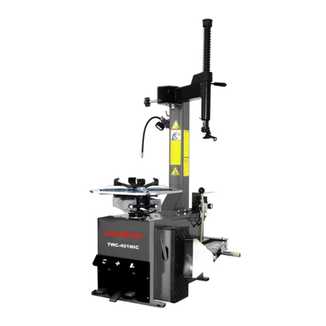
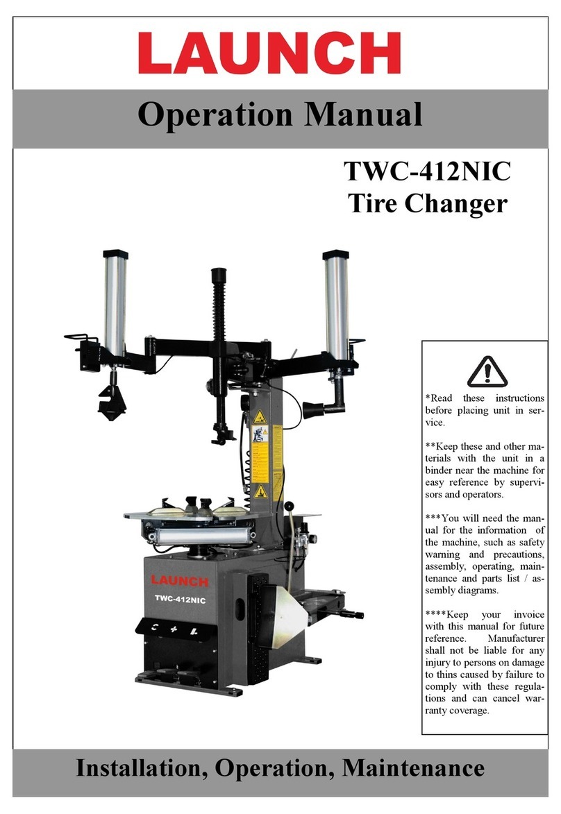
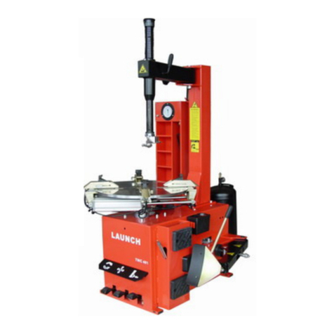
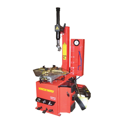
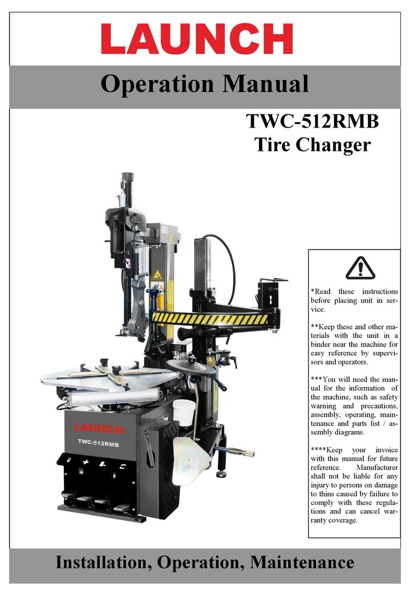
Launch TWC-711 User manual

V1.00.000
2012-10-23

LAUNCH TWC-711TMBTireChangerUser'sManual
i
Trademark Information
LAUNCH is a registered trademark of LAUNCH TECH. CO., LTD. (LAUNCH for short) in China and other countries. All other
LAUNCH trademarks, service marks, domain names, logos, and company names referred to in this manual are either
trademarks, registered trademarks, service marks, domain names, logos, company names of or are otherwise the property
of LAUNCH or its affiliates. In countries where any of the LAUNCH trademarks, service marks, domain names, logos and
company names are not registered, LAUNCH claims other rights associated with unregistered trademarks, service marks,
domain names, logos, and company names. Other products or company names referred to in this manual may be
trademarks of their respective owners. You may not use any trademark, service mark, domain name, logo, or company
name of LAUNCH or any third party without permission from the owner of the applicable trademark, service mark, domain
name, logo, or company name. You may contact LAUNCH by visiting Launch at http://www.cnlaunch.com, or writing to
Launch Industrial Park, North of Wuhe Rd., Banxuegang, Longgang, Shenzhen, Guangdong, P. R. China., to request written
permission to use Materialson this manual for purposes or forall other questions relating to this manual.
Copyright Information
Copyright © 2012 by LAUNCH TECH. CO., LTD. All rights reserved. No part of this publication may be reproduced, stored in
a retrieval system, or transmitted in any form orby any means, electronic, mechanical, photocopying, recording or otherwise,
without the prior written permission of LAUNCH. The information contained herein is designed only for the use of this unit.
LAUNCH is not responsible forany use of thisinformation as applied to other units.
Neither LAUNCH nor its affiliates shall be liable to the purchaser of this unit or third parties for damages, losses, costs, or
expenses incurred by purchaser or third parties as a result of: accident, misuse, or abuse of this unit, or unauthorized
modifications, repairs, or alterations to this unit, or failure to strictly comply with LAUNCH operating and maintenance
instructions.
LAUNCH shall not be liable for any damages or problems arising from the use of any options or any consumable products
other than those designated asOriginal LAUNCH Products or LAUNCHApproved Products by LAUNCH.
General Notice
Other product names used herein are for identification purposes only and may be trademarks of their respective owners.
LAUNCH disclaims any and allrights in thosemarks.

LAUNCH TWC-711TMBTireChangerUser'sManual
ii
Safety Precautions
Please read the manual carefully before use and strictly follow the instructions in the manual during operation.
This machine can only be used for the designated purposes. Never use it for any other purpose. The manufacturer is
not held responsible for the damage incurred by improper use or use other than the intended purpose or modification
without agreement from the producer.
The equipment can only be operated by qualified personnel with special training.
Before use, please check carefully whether thescrews of the machine are loose or not.
During operation, non-operators should not approach the safety signs, and the signs should not be removed.
During normal operation, keepyour body away from the movingparts.
During operation and maintenance, all the laws and regulations must be followed to prevent from accidents.
This machine should be installed on the stable ground to prevent from rocking duringoperation.
The machine should be grounded, protective measures shouldbe taken to prevent from leakage.
Air source and power supply must be cut off before maintenance.
When the machine has error inrunning, the power supply must be cut off first, and then correct the fault.
During operation, keep your hands and body away from moving parts. Necklace, bracelet, loose clothes and hair are
quite dangerous for the operators. Operators should wearproper safety suits, gloves, goggle,etc.
Keep the working area clean,mess area can easily cause accidents.
Avoid using the machine in dangerous working circumstances, do not use pneumatic nor electric devices in humid
areas or expose them in them rain.
The working environment should be well lit.

LAUNCH TWC-711TMBTireChangerUser'sManual
iii
Safety signs description
During fixing demounting head or
turning turntable, pay attentionto
the distance between demounting
head and hands and other body
parts.
High voltage! Be careful of electric
shock!
Be careful while connecting and
pulling out air pipe.Air source
should be cut off first, air in the
machine must be drained off to
prevent from hurting the workers.
MAX 10bar
Compressed air network does not allow
more than 10 bar.
Be very careful with splitter, the
splitter will be moving fast and
strongly when the breaking pedal
is depressed. The operator needs
to pay attention to the safety ofhis
body and items within his working
site.
Pay attention to hands and other body
part during clamping operation.
Note: during bead breaking, ifthe
clamping cylinder is open, itwill
scratch the operator's hands.
Remember not to touch the tire
sidewall during bead breaking.
Before inflating, please check whether
the tires and rims are intactand well
matched, otherwise it is extremely
dangerous when error occurs,as it may
cause an explosion, which will injure the
operator or the people aroundor even
to death. If the inflating pressure is too
much higher than the prescribed air
pressure, such accidents will also
appear.
When clamping the rims, hands
and other body parts should not
enter into the space between rim
and jaw.
During operation, operators should wear
proper clothes, long hair and ornaments
may contact the moving part,which may
cause accidents.

LAUNCH TWC-711TMBTireChangerUser'sManual
iv
Sketch of locations of some safety signs
When the safety sign is blurredor lost, the new logo should be replaced immediately;
Please do not use this equipment when one or more signs are lost;
The signs should be clearly seen by the operators.

LAUNCH TWC-711TMBTireChangerUser'sManual
v
Table of Contents
Chapter I Overview..................................................................................................................................................................1
1.1 Introduction.....................................................................................................................................................................1
1.2 Features..........................................................................................................................................................................2
1.3 Technical specifications...................................................................................................................................................2
1.5Applicable range .............................................................................................................................................................2
Chapter II Basic operations....................................................................................................................................................3
2.1 Instructions on pedal working conditions........................................................................................................................3
2.2 Splitting...........................................................................................................................................................................4
2.3 Mounting.........................................................................................................................................................................6
2.4 Inflating...........................................................................................................................................................................8
Chapter III Repair and maintenance......................................................................................................................................9
3.1 Daily maintenance and cleaning:.................................................................................................................................9
3.2 Maintenance during disabling period............................................................................................................................10
3.3 Discarding.....................................................................................................................................................................10
Chapter IV Common trouble and troubleshooting methods.............................................................................................11
CE Declaration of Conformity..............................................................................................................................................12

LAUNCH TWC-711TMBTireChangerUser'sManual
1
Chapter I Overview
1.1 Introduction
TWC-711TMB tire changer with assisting swing arm(figure 1)is one of the advanced tire changer series in the world,
integrated with demounting,mounting and inflating functions. It adoptspopular international dwarf cabinet structure with
good reliability, reasonable overall structure and the high degree of mechanization.
Figure 1
1. Inflating control pedal 2. Clamping pedal 3. Splitter control pedal
4. Turntable control pedal 5. Splitter 6. Pneumatic tire changer hook
7. Hexagon rod 8. Hexagon locking handle 9. Pneumatic control handle
10. Hexagon rod adjusting knob 11. Assisting arm operation handle 12. Lateral rocker positioningknob
13.Airreceiverbarometer 14.Assistingarm 15.Barometer
16.Dischargingbutton 17.Jaw 18.Turntable
19. Turntable cylinder 20. Assisting swing arm 21. Demounting head swing arm

LAUNCH TWC-711TMBTireChangerUser'sManual
2
1.2 Features
zIntegrated with demounting,mounting and inflating functions;
zEquipped with 2-range bead breaking pedals with larger space;
z2-range movable jaw, flexible, better suitable for demountingand mounting of flat tire with different specifications;
zAdopted demounting head with no crowbar, pneumatic controlled pulling tire internal rim. Reasonable design, reliable
performance, sturdy and durable;
zAdopted simple assisting arm, faster and more convenient for demounting and mounting tire, good reproducibility,
better protect the tire rim and to improve the quality of tire demounting and mounting.
1.3 Technical specifications
zWeight of machine: 248kg
zWorking pressure: 0.8-1.0Mpa
zMotor power: 1.1kw (1.5Hp) 0.75kw(1Hp)
zTechnical specifications for electric appliances:
220v 1hp 50HZ-60HZ
110V 1hp 60HZ
380V 3hp 50HZ
zTurntable revolution: 7r/min
zMax. tire diameter: 1100mm(43”)
zMax. tire width: 355mm(14”)
zLocking rim range:external:12”-26”(305-660mm) internal:14”-28”(355-711mm)
zWorking temperature: 0-50℃
zNoise: <70dB
zForce on splitter: 2500kg(5500lb)
1.5 Applicable range
zMax. tire diameter:1100 mm (43”)
zMax. tire width:355mm (14”)

LAUNCH TWC-711TMBTireChangerUser'sManual
3
Chapter II Basic operations
Before use, read the following guidelines carefully:
zDuring operation, suitable protective clothing, gloves, goggles, etc should beworn for protection.
zDuring operation, non-operators should not approach the warning signs and the signs cannot be removed.
zBefore using, air source must be turned on first, and then depress on sliding clamp control pedal to makesliding clamp
to retract for several times, do not power on turntable until the oil-mist separator begins to generate oil, otherwise it
could easily tear the rubber gasket of the rotary valve and cause trouble.
zWhen the machine has error during running, power should be cut off first, and then repair the fault.
zMounting and demounting requirements on special tires from the manufacturer should be paid attentionin any case.
zDuring operation, legs should not be put between pressure pedal and rubber stop so as to avoid personal injuries
caused by stepping on the wrong pedal.
zThe positions of demounting head and rim should be tightened after they are adjusted. And hand wheel should be
screwed tightly onto the cross arm to prevent damages to themachine and tire and personal injuries during operation.
zWhen the demounting head is placed in working position, hands should not be put on the tires to avoid personal injury.
zDuring clamping the rims, hands should not be put between tire and jaw to avoid personal injury.
zWhile approaching the tire, jawshould be closed to avoid personal injury.
zWhen the machine is running, the staff should be concentrated on it.
Pressure settings: As the machine works properly with pressure of 8-10bar, the coherent source pressure should be more
than 7bar.
Demounting head settings: When the machine is delivered, the demounting head is calibrated with standard 13" rim. If
there are exceptionally large or small rims, simply loosen the two column ends on the demounting head and the bolt at the
bottom of the hexagonal shaft, then rotate the demounting head, finally tighten the screw when curvature of the demounting
head can basically meet therim.
Oil volume settings: oil volume of atomized lubricator is calibrated when delivery. If the oil feeding speed is too fast or too
slow, adjust the needle of atomized lubricator with a screwdriver, and then depress the splitter control panel for 5–6 times till
a drop of oil dropped from lubricator. Always check the oil level in the cup, replenish with # 30 machine oil in time when
lacked.
2.1 Instructions on pedal working conditions
zInflating control pedal “ ”: There are 2 ranges: range 1 and range 2. Range 1 is located at the middle while range
2 is at the bottom. Range 1 is used for inflating tires with inner tubes and easily inflated vacuum tires, while range 2 is
used for inflating special vacuum tires.
zClamping pedal“ ”: There are 2 ranges: range1 at top and range 2 at bottom.
zSplitting control pedal“ ”: There are 2 ranges: low range and initial range.The pedal mustbe depressed and hold
to ensure it at low range; if the pedal is released, it will go back to initial range. Low range is for bead breaking action,
while initial range is for release action.
zTurntable control pedal “ ”: There are 3 ranges: low range, initial range and high range. The operation method

LAUNCH TWC-711TMBTireChangerUser'sManual
4
is the same with splitter pedal. Depress and hold the pedal, it is at low range; push up and hold the pedal, it is at high
range; release the pedal, it is at initial range. Low range is for clockwise rotation of turntable, high range is for
counterclockwise rotation of turntable, and initial rangeis for motionless turntable.
2.2 Splitting
Warn: If splitting is blocked, vehicle must be stopped immediately, and push up the turntable rotating control pedal
so that the turntable will rotate counterclockwise to eliminate resistance, otherwise capacitor and motor may be
damaged.
Preparation work:
zDeflate the air in the tire completely.
zRemove the sundries and balance block on the wheel to avoid accident, as
shown in figure 2-1.
zEffective lubricants (such as concentrated soapy water) should be used to
lubricate the rims so as to avoiddamages to the tire during operation.
Warn: Special tools should be used to remove the balance block to avoid
damagestorim. Figure 2-1
Operating steps:
1. Place the wheel between the splitter and rubber stop, place splitter between wheel edge and rim, then depress on the
splitting pedal to split the rim from the bead, as shown in figure 2-2.
Note: Before splitting, brush the concentrated soapy water in the container onto the bead for lubrication, as shown in figure
2-3
Figure 2-2 Figure 2-3
2. Perform repeated operations as above in other partsof the tire to split rim completely from bead.
3. Place the tire with loose edge on the sliding jaw to clamp the tire, then depress the clamping pedal to hold the tire (for
unsymmetrical rims with deep slots, the narrow rim should be placed upward.)
Note: Different clamping methods can be chosen according to different rims.

LAUNCH TWC-711TMBTireChangerUser'sManual
5
¾If to choose internally locking, draw back the jaw first, then place wheel on the turntable, finally depress clamping
cylinder pedal “ ” to clamp the rim.
¾If to choose externally locking (as shown in figure 2-4), stretch out the
jaw first, then place the wheel on the turntable to allow the two jaws inside to
clamp on the rims, hold the proximal side of tire by hands, depress clamping
cylinder pedal “ ” to place pedal at low range, jaws begin to tighten.
Observe the relativepositions of thetwo proximal jaws to rims, when theyare
close to the rim, lower downthe proximal side, jaws will clamp the rimtightly.
Figure 2-4
4. Adjust the demounting head,place it on the working position at upper rim, screw lateralrocker positioning hand wheel (12
as shown in figure 1,), lock the hexagon rod (①and ②as shown in figure 2-5). To avoid scratches in rim, place the
demounting head with a distance of about2mm from the upper rim side and edges, and then tighten the demounting head,
as shown in figure 2-6.
Figure2-5 Figure2-6
Note:
1. Due to prolonged use of rims, it is difficult to ensure roundness and parallelism. When the demounting head is in the
working position, find the maximum point of the rim and the highest point of roundness first. Then fix the demounting head
according to these two pointsto avoid scratching rims while demounting the wheels.
2 The positions of demounting head and rim should be tightened after they are adjusted. And hand wheel should be
screwed tightly onto the cross arm to prevent damages to themachine and tire and personal injuries during operation.
5. When stepping on the turntable pedal, move down pneumatic control tire changer hook till the hook extends into the
inner edge of the bead disengaged and provoke it (as shown in Figure 2-7), point step on turntable rotating pedal, so
turntable rotates clockwise till all the bead is taken out (Figure 2-8),

LAUNCH TWC-711TMBTireChangerUser'sManual
6
Figure2-7 Figure2-8
Note:
¾If splitting is blocked, vehicle should be stopped immediately, push up the turntable rotating pedal with foot to allow
turntable rotate counterclockwise to eliminate obstacles.
¾If there is inner tube during operation of this step, it is suggested to operate with a distance of about 10cm from the
right ride of the tire valve.
6. If there is inner tube, take itout.
7. While splitting another side of bead, place it onto the pneumatic control hook, allow turntable to rotate clockwise till all the
bead is taken out, as shown in figure 2-9 and 2-10.
Figure2-9 Figure2-10
2.3 Mounting
Preparation work
Check the dimensions oftire and rim to see if they are the same;
Clean the rim, check whether there is dust or distortion, etc inthe beadseat;
Check whether the bead is distorted or bent, etc.

LAUNCH TWC-711TMBTireChangerUser'sManual
7
Operating steps:
1) Place the rim on the sliding clamp, hold and clamp to fix it (the same way as splitting).
2) Coat effective lubricants on tire and rim, such as concentratedsoapy water, etc.
3) Place the tire on the rim tilted, left part on top, draw back the swing arm to the working position, tighten the demounting
head.
4) Place bead on the tail-boardof demounting head (as shown infigure 2-11), and place tire at the bottom of hook.
Figure 2-11
5) Lubricate the wheel edge with soapy water, rotate the turntable clockwise to allow bead drop into the rim slots. If there
is inner tube, put it onto the rim.
6) While mounting another side of the tire, place bead on the tail-board of demounting head, and place tire at the bottom
of hook, meanwhile, press tire body on another side with assisting arm, as shown in figure 2-12
Figure 2-12
7) Rotate the turntable clockwise, remove the assisting arm when about 3/4 of the bead goes into the rim slots, then
continue to rotate the turntableclockwise till all the bead goes into the rim slots.
Note: Bead cannot be damaged during mounting to avoid poor gas tightness and burst accidents.

LAUNCH TWC-711TMBTireChangerUser'sManual
8
2.4 Inflating
The machine is equipped with a universal inflating gun, convenient and flexible. Equipped with a pressure meter, the
pressure in the tank can be observed at any time to ensure that sufficient gas can be provided when needed for less
inflatable vacuum tires.
Note:
Operation regulations should be strictly followed during tire inflating, gas circuit connection must be confirmed before
inflating.
During inflating, hands shouldnot be putbetween rim and tire to avoid personal injuries.
During inflating, tire pressure should be increased uniformly, and the state of the bead shouldbe paid attention to.
During fast inflating, goggles should be worn toavoid debris falling into eyes.
Steps:
1. Connect the inflating gun connector to tire valve.
2. Inflating methods for tireswith inner tubes or easily inflatablevacuum tires:
Depress the inflating pedal to range 1, after inflating for a certain time, release the pedal, make sure the pressure
displayed on the meter within the range indicated by tire manufacturer. If it is out of range, press discharge button (as
shown 16 in figure 1) to release excessive gas.
3. Fast inflating methods:
For direct inflating with inflating gun, gas may leak from the bead, and bead cannot be placed against rim tightly. The
correct way is to push up tire so that bead can be tightly placed against rim first, then while inflating with the gun,
depress fast inflating pedal to range 2 for assistant inflation, so that large amount of gas can be inflated into the tire
quickly, then put bead closely against the rim, switch back to normal inflation mode. Make sure the pressure displayed
on the meter within the range indicated by tiremanufacturer.
Note:
¾The operator must be concentrated during tire inflation, hands and body should be kept away from the tire to avoid
personal injuries.
¾Before inflating, tire must be checked for damages, and pressure in the tire cannot be more than 3.5bar, as incorrect
tire pressure will influence tire lifetime, vehicledriving safety and operation stability.

LAUNCH TWC-711TMBTireChangerUser'sManual
9
Chapter III Repair and maintenance
3.1 Daily maintenance and cleaning:
Note: Before maintenance, power supply and air source must be cut off.
zCheck the oil level of atomized lubricator cup, if oil needs to be filled, cut off the power supply first, remove the cup, fill
with mineral oil SAE30.
zClean the oil cup and condensation in oil mist separator regularly.
zClean all the motional parts (asshown in figure 3-1) of clamp ring.
Figure 3-1
zCheck and tighten the bolts for all the connection parts regularly.
zKeep the dryness and cleanness of internal hexagon rod (clean with diesel) (as shown in figure 3-2)
Figure 3-2
zCheck tension of drive belt. When adjustment needed, loosen the motor fixing bolt, tune the motor to proper position
and then tighten the bolt againto achieve tensioning of drive belt.(as shown in figure 3-3)
Figure 3-3
zKeep machine and working area clean to avoid dust going into the moving components.

LAUNCH TWC-711TMBTireChangerUser'sManual
10
zThe binding surfaces which can generate relative displacement and relative friction should be lubricated with
lithium-base grease every week.
zClean the silencer in control valve and fast valve to avoid influence on the normal operation of cylinder. The silencer
should be taken out and washed with water or the dirt can be blown away by compressed air.
zThe sundries on the disc should be cleaned every time after tire demounting and mounting to avoid wear to table plate
due to too many sundries during use.
zAfter vertical shaft is tightened, there is too much upward and downward motion, which can be repaired as follows:
Cut off the air source, remove the protective cover of vertical shaft, adjust the stop nut at screw rod or tighten the
jackscrew at the front end of plate with a wrench till the vertical shaft can be tightened.
3.2 Maintenance during disabling period
If the machine is left unused for a long time, power and gas source should be cut off, and the residual gas inside the
machine should be emptied. Wipe the surface of the machine, except from the sprayed surfaces, all the other surfaces
should be coated with oil and covered to avoid rust, moisture and dust. When the machine is put back into use, checks
should be performed according to the descriptions above to see if all the functions are normal.
3.3 Discarding
If it is decided that the machine is no longer to be used again, the power and gas sources should be removed, and the
machine should be disassembled and classified, such as metal, plastic, oil, etc and then processed in accordance with local
regulations.

LAUNCH TWC-711TMBTireChangerUser'sManual
11
Chapter IV Common trouble and troubleshooting methods
Trouble Possible reasons Solutions
Unilateral rotation of turntable Universal switch is damaged
Limit stud height is incorrect Replace universal switch
Adjust the height of limit stud
Turntable does not rotate Belt is damaged;
Universal switch is damaged
Trouble with motor
Replace belt
Replace universal switch
Check the motor plug and socket to
see if it is loose, replace motor
Turntable cannot lock the rims
correctly Jaw is worn or cylinder under
turntable is defective Replace jaw and cylinder sealing
ring
Clamping pedal and bead breaking
pedal cannot reset Resetting spring is damaged Replace resetting spring

LAUNCH TWC-711TMBTireChangerUser'sManual
12
CE Declaration of Conformity

LAUNCH TWC-711TMBTireChangerUser'sManual
13
Warranty
THIS WARRANTY IS EXPRESSLY LIMITED TO PERSONS WHO PURCHASE LAUNCH PRODUCTS FOR PURPOSES
OF RESALE OR USE INTHE ORDINARY COURSEOFTHE BUYER’S BUSINESS.
LAUNCH electronic product is warranted against defects in materials and workmanship for one year (12 months) from date
of delivery to the user. This warranty does not cover any part that has been abused, altered, used for a purpose other than
for which it was intended, or used in a manner inconsistent with instructions regarding use. The exclusive remedy for any
automotive meter found to be defective is repair or replacement, and LAUNCH shall not be liable for any consequential or
incidental damages. Final determination of defects shall be made by LAUNCH in accordance with procedures established
by LAUNCH. No agent, employee, or representative of LAUNCH has any authority to bind LAUNCH to any affirmation,
representation, or warrantyconcerning LAUNCH automotive meters, except as stated herein.
Disclaimer
THE ABOVE WARRANTY IS IN LIEU OF ANY OTHER WARRANTY, EXPRESSED OR IMPLIED, INCLUDING ANY
WARRANTY OF MERCHANTABILITY OR FITNESS FORAPARTICULAR PURPOSE.
Order Information
Replaceable and optional parts can be ordered directly from your LAUNCH authorized tool supplier. Your order should
include the following information:
Quantity
Part number
Item description
Customer Service
If you have any questions on the operation of the unit, please contact us: +86-4000666666.
If your unit requires repair service, return it to the manufacturer with a copy of the sales receipt and a note describing the
problem. If the unit isdetermined to be in warranty, itwill be repaired orreplaced at nocharge. Ifthe unit is determined to be
out of warranty, it will be repaired for a nominal service charge plus return freight. Send the unit pre-paid to:
Attn: Customer service centre
LAUNCH TECH. CO., LTD.
Launch Industrial Park,
North of Wuhe Rd.,
Banxuegang, Longgang,
Shenzhen, Guangdong, P. R.China
Table of contents
Other Launch Tyre Changer manuals
Popular Tyre Changer manuals by other brands

CEMB
CEMB SM825AIR Use and maintenance manual

Aston Global
Aston Global ATC-8823 Installation, Operation and Maintenance User’s Manual

SICE
SICE S 45 TL instruction manual

Hunter
Hunter TCX50H Series Operation manual

TMG
TMG TMG-TC24 product manual

Hofmann Megaplan
Hofmann Megaplan megamount 601 Installation, operation and maintenance guide