Launch TWC-502RMB User manual

LAUNCH TyreChanger(TWC-502RMB)
i
TableofContents
SafetyPrecautions ... 1
MainStructure .... ..2
Tools .. ..4
Installation ... ..4
Unpacking ... ....4
Installation ... ..4
Transport .6
Positioning ..........6
Power and Air Connections .......6
Adjusting .. 6
Initial Operation .. ... 6
Clamping Unit of the aws ...................... ....7
Drive system .. 7
Bead Breaker ... .. ....8
Tilting column nit .. .. .. .8
Horizontal Arm and Hexagonal Column Clamping
Unit ........9
SupplementaryArm............ ..9
Mount/demountHead .10
Air Pressure Regulator,Gauge andLubricator
Assembly .. ...13
PartsList .. ... .. .14
TWC-502RMBCircuitDiagram .. .30
TWC-502RMBPneumaticDiagram ..33
PDF 件使用 "pdfFactory Pro" 试用版本创建 www.fineprint.cn

LAUNCH TyreChanger(TWC-502RMB)
1
SafetyPrecautions
lThis manual is anecessary component of the
product. Please review carefully.
lKeep the manual for later usewhen maintaining
the machine.
lThis machine can only be used for the designed
purpose. Never use it for any other purpose.
lThe manufactureris notheldresponsiblefor any
damage incurred byimproperuse or use for the
purposes other than the intended one.
Before installing and adjusting the equipment, pay
attention to the following:
lRead this manual and all other instructions for
the equipment thoroughly.Modification to any
components or parts, or usethe machine for
other purpose without either obtaining the
permission fromthe producer,or observing the
requirement of theinstructionsmay leadto direct
or indirect damage to the equipment.
lThe installation and adjustingpersonnel should
have a good understanding of electrical devices.
lThe equipment canonly beoperatedby qualified
personnel with special training.
lTWC-502RMB shouldbe installed onthe smooth
ground.
lKeep the back panel 0.75M away from thewall
for good ventilation. Enoughroom shouldbe left
on both sides of TWC-502RMB for convenient
operation.
lDo not put TWC-502RMB inaplace with high
temperature or moisture, ornear the heating
system, water tap, air-humidifier or furnace.
lDo not install TWC-502RMB near awindow with
sunlight. Protect the unit with a curtain or shield
if necessary.
lGo through the accessory list carefully before
installation. Should there be any questions
please contactyour agent orLaunch Tech Co.,
Ltd.
PDF 件使用 "pdfFactory Pro" 试用版本创建 www.fineprint.cn

LAUNCH TyreChanger(TWC-502RMB)
2
Main Structure
Fig.01-1
A Return spring B Swing arm C Hexagonal column
D Mount/demount head
E Clamping jaw F Turntable G Tilting column
control pedal H Clamping cylinder
control pedal
I Bead breaker
control pedal J Turntable control pedal K Hexagonal column
locking handle L Tilting column
N Clamping cylinder
assembly O Hanger P Bead breaker
handle Q Bead breaker arm
R Ajusting pin S Bead breaker shoe T Tyre lever U Inflation pedal
V Air Pressure Regulator, Gaugeand LubricatorAssembly W
Supplementary arm
assembly
PDF 件使用 "pdfFactory Pro" 试用版本创建 www.fineprint.cn

LAUNCH TyreChanger(TWC-502RMB)
3
Fig.02-1
Fig.02-2
Fig.02-3
Fig.02-4
The Supplementary arm is shown in Fig. 02-1.
a- Swivel arm assembly
b- Disk arm assembly
c- Slide rod assembly
d- Lock cylinder assembly
e- Slide board assembly
f- Post assembly assembly
g- Lifting cylinder assembly
h- Press block
i- Disk
j- Control box assembly
k- Lock bar
Swivel arm assembly is shown in Fig. 02-2
a1. Fore swivel arm
a2. Middle swivel arm
a3. Back swivel arm
a4. Press slideset
Disk arm assembly is shownin Fig. 02-3
b1. Roller of disk arm
b2. Disk
b3. Disk arm
b4. Locking slide bar
b5. Knob
b6. Control box
b7. Lock cylinder
b8. Button valve
b9. Reversing valve
Slide rod assembly is shown in Fig. 02-4
C1. Roller 1
C 3. Knob
C4. Slide rod
C5. Lock bar
PDF 件使用 "pdfFactory Pro" 试用版本创建 www.fineprint.cn

LAUNCH TyreChanger(TWC-502RMB)
4
Tools
Toensure the correct installation and adjusting, please
get the following tools ready:
Two adjustable wrenches, one set of boxspanners,
one pair of pliers, one set of screwdrivers, one digital
multi-meter (for voltage measurement).
Installation
Unpacking
lRemove packingfollowing theinstructionson the
package. Remove the packing materials and
check the machinefor possible damageor loss
of accessories during transportation.
lKeep the packing materials out of the reach of
children. Handle them in an appropriate way if
the packing materials cause pollution.
lRemove the cabinet, tilting column t, horizontal
arm and accessory box fitted on the bottom plate
and put them in safety place.
Installation
InstallationofTitling column(Fig.03)
Fig.03
lPlace the cabinet at the right position.
lRemove thefront boardandbottom rotation shaft
of tilting column with appropriate tools.
lApply lubricant on bottom rotation shaft and its
sleeve.
lLift up the tilting column .Run the PU hose
through inlet onthe cabinet, andposition the
tilting column onto the bottom seat.
lAlign the round holes on the bottom rotation
sleeve and the side boards of thebottom seat,
then knock the rotation shaftthrough holeswith a
hammer.Use awood block between hammer
and the shaftfor protectionwhen knocking. Fit
gaskets on both sides of the shaft before
fastening screws.
lRemove the bolt and nut from the piston rod of
the tilting column cylinder.Get the bolt through
round holes on side boards of thetilting column
and the piston rod. Lock it with the locking nut.
lAdjust four adjusting bolts to make the tilting
column on the right position (SeeTitling Unit)
lMount the front board to original position.
Caution:
Special anti-rust oil is applied on the delicate parts
may attract dust. Clean it when necessary.
InstallationofSupplementaryarm
device
lTake out assembly of back swivel arm, postand
lifting cylinder,remove the hood(Fig.04). Then
take out disk assembly and relevant fastening
parts, apply lubricant on the fastening parts,
assemble them as Fig.05, mount back the hood
.
Fig.04
Fig.05
lRemove thebolts (Fig.06) andwasherson right
side plate of cabin, place the unit (Fig.05) onthe
seat vertically,
lFit washers and fasten themwith bolts. Get the
air compressing hose out fromthe bottom of post
PDF 件使用 "pdfFactory Pro" 试用版本创建 www.fineprint.cn

LAUNCH TyreChanger(TWC-502RMB)
5
into cabinet through small hole on its right side
plate.
Fig.06
lTake out Slide rod and relevant fastening parts,
brush lubricant on the parts, then assemble them
as in Fig.07.
Fig.07
lTake the bless block on tyrecenter,assemble it
on fore swivel arm as in Fig.08.
Fig.08
Fig.09
AirConnections
lAfterthepostandsupplementaryarmfixed,
disassemble thesideboardofthecabinet
lFind air compressing hoses out from the post ,
supplementary arm and airt-tank, insert them
into joint respectively. (Fig.09)
lShowninFig10, getthetwooutletairlines
oftheairpressureregulator,gaugeand
lubricatorassemblythroughtheroundholes
ofthecabinetrearcompartmentintothe
cabinetinside,connecttheairline1with
tyre-inflatingairlinegroup(T-joint),connect
theairline2withthecylinderairlinegroup.
Fig.10
InstallationofAirTank
lFix the air tank on the cabinet with two sets of
bolts, nuts, spring washers andflat washer (Fig.
11).
lConnect the rubber hosewith thejoint onthe air
tank and fasten the screw ofthe hose hoop as
figure 11
PDF 件使用 "pdfFactory Pro" 试用版本创建 www.fineprint.cn

LAUNCH TyreChanger(TWC-502RMB)
6
Fig.11
Fig.12
Fig.12
lconnecttheairlineoftheair-tank withone
branchofT-jointasFig12..
lAssemblethecabinetsideboard
InstallationofBarometer
Install the barometer on one side of thetilting post
according to figure 13.
Fig.13
pleaserefertotheTWC-502RMBgasroad map
to find outthespecificconnection method
Transport
It is advisable to transportthe machine withfork lift
vehicle.
lSuch movable parts: tray assembly,Bending arm
assembly,straight arm assembly,tilting column
and horizontal arm must be fastened to the
cabinet tightly with rope to avoid damages to
machine and injuries to people during
transportation.
lAvoid excessive tilting in transportation.
lDon’tdrive the fork lift vehicle carrying the
equipment too fast.
lTry to keep the machine at the lowest position
and make sure it won’toverturnin transportation
(pay attention to the position of the gravity
center).
Positioning
The place to install themachine shouldbe in
accordance with safety regulations:
lThe machine should be installed in aplace close
to the main power and compressed air source.
lInstall the machine on smooth concrete ground
or other ground with hard flooring. 4sets of
anchor bolts(M10×150)can beused tofasten the
machine onto the ground strongly to avoid
vibration and noise.
lLeave enough space aroundthe machine for
proper operation and maintenance. The space
should be no less than 1M in front and onthe two
sides of the machine and 0.5M behind it.
lIf the machine has to be installed outdoors, a
protective shelter should be built.
lFree from flammable gases.
Note:
For the safetyand proper operation,keep the
machine at least 0.75M away from any wall.
Powerand Air Connections
lBefore installation, checkif the power source and
the compressed air are inaccordancewith the
specifications on the nameplate. Any electrical
connection should be done by the specially
trained technician.
lThe power socket should be at aplace within the
sight of the operator.The advisable height is
between 0.6 –1.7M.
lIn case themainvoltageis notstable,avoltage
stabilizer shouldbe usedbetween power source
and the machine.
lThe machine should be well grounded.
The tyre changer isnot equipped with
overload protection. Please connect power
according to the circuit diagram included in the
User smanual. Otherwise, the manufacturer
will not be responsible forany accidents.
PDF 件使用 "pdfFactory Pro" 试用版本创建 www.fineprint.cn

LAUNCH TyreChanger(TWC-502RMB)
7
Adjusting
Attention:
Make sure that thepowersupply,air sources
and the oillevelin theoil cuparein accordance
with the requirements.
Initial Operation (Fig.01)
Note:
The four pedals must be kept at theoriginal
position.
lPress down thepedal (J)to turnthe turntable
clockwise;
lLift the pedal (J) to turn the turntable
counter-clockwise;
lPress down pedal (I) to movebead breaker;
release it to restore;
lPress down pedal (H) to move the jaws on the
turntable outward; pedal again to move them
inward;
lPress down pedal(G), thetilting columnwill tilt
backward. Pedal it again torestore the tilting
column upright.
lWhen the Rise/fall control leverrislifted, the
supplementary arm device will go up.
lWhen the control lever is lowered down, the
supplementary arm device will go down.
lWhen the Inflation pedal U(Fig.01-1) is lightly
pressed, air will spout from the air hose
connected with the barometer.When the pedal is
pressed down to the lowest position, air will
quickly spout behind four jaws (the end ofthe
sliding mouse).
Clamping SystemoftheJaws(Fig.14)
lThe position of the jaw (Fig.15) onthe turntable
is controlled by the movement of the piston rod,
which in turn is controlled by pedal H. There
are three levels for pedal H.
lWhen pedal Hon high, the piston rod will move
inward and pull the jaws moving inward untilthe
minimum. At this time the distance of two
opposite jaws is10”for inner rim and 13”for
outer rim.
lWhen pedal Hon low,the piston rod will move
outward and pull the jaws moving outward until
the maximum. At this time the distance
between two opposite jaws is 20”forinner rim
and 23”for outer rim.
lWhile the jaws in motion, press pedal Hlightly to
keep it atthe middle level,the jaws willstop in
response. Do thisfunctionflexible toget the
jaws anywhere between themaximum and
minimum for different wheels.
Fig. 14
Fig.15
lThe principle of the abovemotion can be
explained by thefollowing:The three positions
on the cam control air reaching different holes on
the 5-way valve, so piston rod of clamping
cylinder is able to move backand forth and stop,
so do the clamping jaws.
Drivesystem
lThe gearing chain: The gearing chain in this
machine is made up of motor,pulley,worm
reducer, turntable and so on (Fig. 16).
Fig.16
lThe motor RPM is about 1400.The ratio of speed
is 200. The rotary directionis controlled by
pedal J.Press down the pedal to make the
turntable rotate clockwise. Release thepedal to
stop the turntable. Lift up the pedal Jwith foot,
PDF 件使用 "pdfFactory Pro" 试用版本创建 www.fineprint.cn

LAUNCH TyreChanger(TWC-502RMB)
8
the motor and theturntable will both turn
counter-clockwise.
lIf contrary to above, change the phase wireof
the motor.
lConnect the ground wire to ground.
lIn the operation, the turntable generally turns
clockwise, only when the operation is obstructed
occasionally, it needs to turn counter-clockwise.
BeadBreaker
lThe bead breaker isonthe rightsideof the
cabinet. As the procedure requires, press down
pedal (I) (Fig.17)o start the bead breaker cylinder,
the piston rod will pull the bead breaker moving
towards the cabinet,with magnitude around
14075N. Release pedal (I), thebead breaker
will retract.
lThe bead breakeris ableto swingwithin a
certain range. In casethe range ofswing is not
appropriate, adjust the nut (Fig.18)at the right
end of the piston rod.
lThe bead breaker arm is adjustable with two
ranges.According to the size of tyre, choose
range 1 or range 2. (Fig.19)
Fig.17
Fig.18
Fig.19
TiltingcolumnUnit
lThe tilting column is under the control of tilting
cylinder in the cabinet,sothat thecolumncan tilt
backward in orderto removethe tyrefrom the
turntable easily,and restore to upright position
(the working position).
lThe tilting cylinder is controlled by pedal G
When it is pressed, the tilting column tilts
backward; and whenit is pressed again, the
column restore to the upright position (Fig.20)
lIf tilting speedis too fastor tooslow,adjust the
throttles to change speed. If the speed istoo fast,
fasten the screw on throttle mouth. If too slow,
loose the screw.The 5-way valve has two
throttles(Fig.21, of which “a”is for tilting
backward while “b”is for back to upright position.
Fig.20
Fig.21
lThere are two bolts on the base plate of the tilting
column to adjust the vertical position of the tilting
PDF 件使用 "pdfFactory Pro" 试用版本创建 www.fineprint.cn

LAUNCH TyreChanger(TWC-502RMB)
9
column. Also, there are two bolts on the side
plates of theseatfor limiting thehorizontal
position of the tilting column. Before operation,
the two bolts on the base plate of the tilting
column should be on the same horizontal level to
ensure bearingthe sameweight. Theside ends
of two bolts should be away 0.5—1mmfrom the
vertical plates of the tilting column.
HorizontalArmand Hexagonal
ColumnClamping Unit
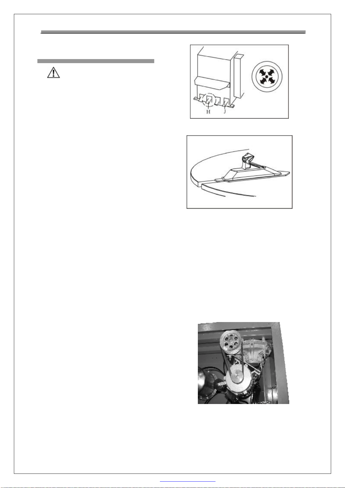
lAs shown in the figure 22 use (air valve) locking
button Jonthe handle(k) tocontrol movement of
the clamping cylinder.Whenthumbeddown the
button, the external shellsof clamping cylinders
(b and g) arepushed out. Their external shells
touch lockingboards (candh). The tiltingof the
boards will lock thehorizontal arm and the
hexagonal column.
Fig.22
lWhen the button is pressed out by index finger,
the clamping cylinder (b andg) will be drawn
back. The tilting boards(c andh) willrelax to
loose the horizontal armand thehexagonal
column. When it doesn’twork, nuts (e and i)
can be tightened or loosened for adjustment.
SupplementaryArm
lFigure 02-1 shows structureof the
supplementary arm that consists of such three
main function units as roller,press block and disk.
The horizontal column unit, swivel armunit, disk
unit and sliding sleeve integrate them together
and can moveup and down alongthe sliding
column under controlof rise/fall control lever on
the control box.When therise/fall controllever is
lifted, the supplementary arm moves up along
with the sliding sleeve. Contrarily,when the
rise/fall controllever ispresseddown, the
supplementary arm moves down. If it causes
flutter when supplementary arm moves up and
down, adjust the four locking screws on the side.
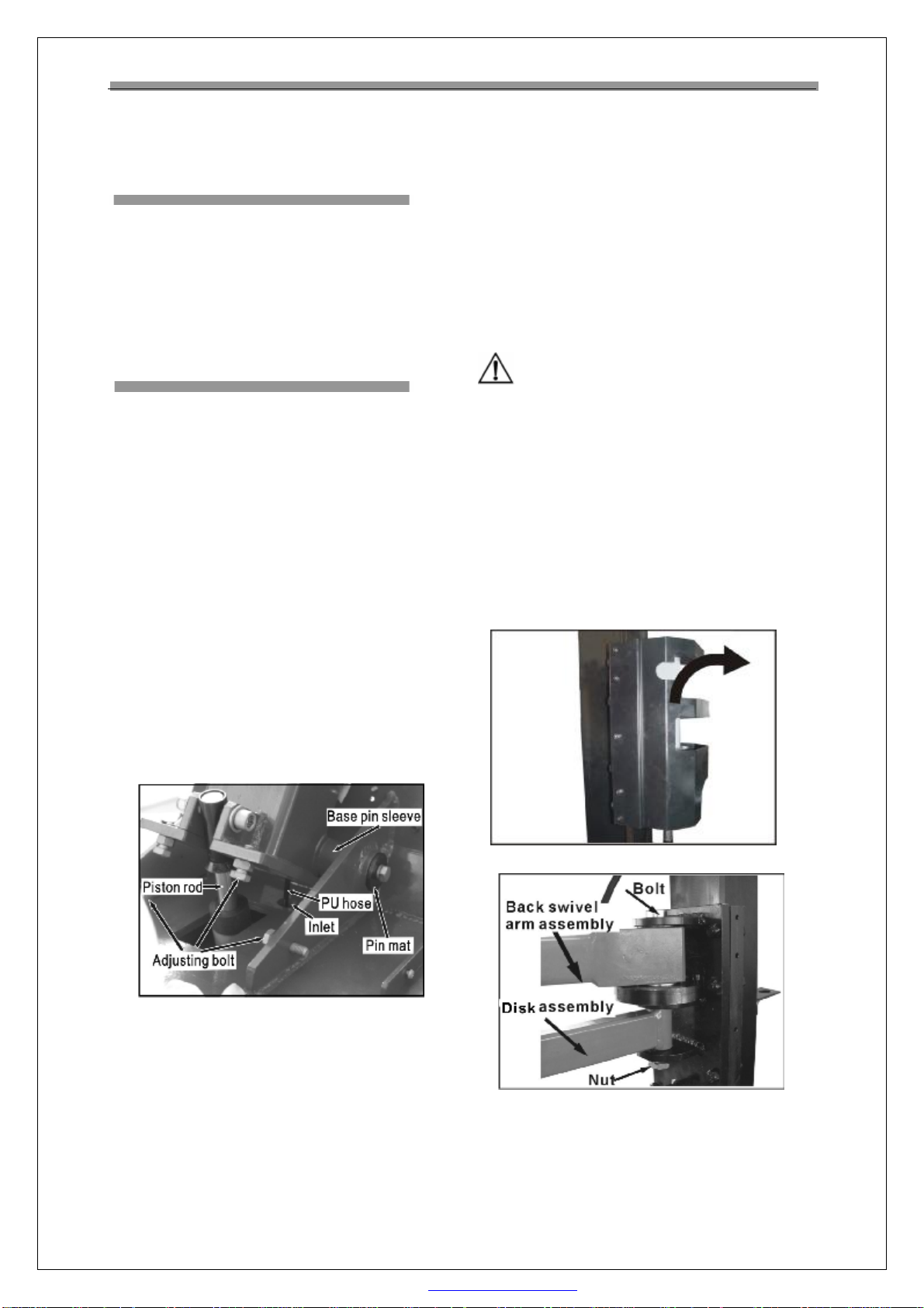
lGroup aof supplementary arm (fig.23). fore
swivel arm (a1) and middle swivel arm(a2) both
can turn freely around corresponding axis of back
swivel arm(a3). press block(h)can move on fore
swivel arm (a1)and fixed on back offore swivel
arm (a1) for centering and pressing rim.
Fig.23
lGroup bof supplementary arm(fig24).roller of
disk arm(b1),with pressblock(h)and roller 1(c1)
is used to mount upper tyre bead under condition
without using mounting head.It also has other
functions. disk(b2) is used to demount tyre by
lifting tyre.switch between roller ofdisk arm (b1)
and disk (b2) by knob (b5).On control box(b6),
there is lockbutton(b8)and rise/fall control
lever(b9). disk arm is controlled by lock
button(b8). lock cylinder(b7) can lock by locking
slide bar(b4), so to control movement of disk arm.
Rise/fall control lever(B9) isto control movement
up and down of the supplementary arm.
Fig.24
lGroup cof supplementary arm as in
fig.25.Choose roller 1(c1) according to need and
fix it on fore part ofslide rod(c4) by knob(c3).
Turn lock bar(c5) to lock slide rod (c4.)
PDF 件使用 "pdfFactory Pro" 试用版本创建 www.fineprint.cn

LAUNCH TyreChanger(TWC-502RMB)
10
Fig.25
Mount/ demountHead
Checking
lMount a15 inch diameter aluminium alloy rim
(preferably new) onto the turntable.
lLower the mount /demount head onto the rim
and lock.
lBy means ofthe appropriate gaugekit, check
measurements as indicatedin Fig.26 for
mount/demount head withroller) and
fig.27(mount / demount head with insert).
If the measurementsdo not correspond proceed as
follows:
Calibration
lLoosen all screws securing themount/demount
head.
lLower the mount/demounthead ontothe rim
and lock.
lFinger-tighten screws A3-A4(Fig.30 and Fig.31in
order to turnthe mount/demounthead and
obtain the correct position.
lTighten screws A1-A2(Fig.28,32)
mount/demount head with roller; Fig.29, 33
mount /demount head with insert) to tilt the
mount /demount head and obtain the correct
position and then finger-tighten screw B.
lUnlock and raise thehexagonal column, then
lower it onto the rim and lock again.
lFirst tighten screws A1-A2-A3-A4 in torque of
50Nm and check by meansof gauges that the
measurements remain the same.
lLastly,tighten screw Btoatorque of 50Nm and
carry out checks once again with the gauges.
Periodic checks
After use of themachine for half ayear,doregular
check to ensure correct measurements as stated in
Checking. If they are incorrect proceed as follows:
lCheck that the screws(A1-A2-A3-A4-B) are
tightened properly and repeatcalibration as per
Calibration.
lIf measurement 2(roller,Fig.28) or measurement
1(insert, Fig.29)are changed,the causemay be
that nut i(Fig.25) has loosened.
lTighten or loosen nutito increaseor reduce
lifting range.
lIf measurement 2(Fig.30) has changed, this may
be due to loose nut e(Fig.22)or deformation of
locking plate c(Fig.22).in both casesimply adjust
the nut, tighten or slackento increaseor reduce
movement range.Securenuts withminimum
tightening torque 70Nm.
Fig.26
PDF 件使用 "pdfFactory Pro" 试用版本创建 www.fineprint.cn

LAUNCH TyreChanger(TWC-502RMB)
13
Fig.32 Fig.33
AirPressureRegulator,Gaugeand
LubricatorAssembly
lAs shown in Fig.34,there is abutton on the
regulator.When pulled up, the pressure can be
increased ordecreasedby turnit clockwise or
counter-clockwise. Afteradjusting the operation
pressure, press the button downto lock it.
lThe air cleaner works to filter thewater and
impurity in the compressed air.When water
and impurities run beyond thered line, turn open
the draining valve to release them.
lThe lubricator is used to add acertain amount of
lubricant into gas for the moving parts inthe
cylinder and regulator.Depress pedal Hor J
3~5times, adrop of lubricant will fall intothe
cup in the regulator.If it does not happen, the
adjusting screw need to be adjusted.
Fig.34
Directionoftheswitch’sinstallation
Fig35
PDF 件使用 "pdfFactory Pro" 试用版本创建 www.fineprint.cn

LAUNCH TyreChanger(TWC-502RMB)
15
PartsList
This list isonlyfor thereferenceofthe maintenance personnel.The manufacturer will notbe held responsible forany
use other than the designed purpose.
In case any damage occurs, please contact your dealer or LAUNCH with the corresponding codes in the list.
Note: Thewearing partsareindicatedby*.
PDF 件使用 "pdfFactory Pro" 试用版本创建 www.fineprint.cn
Table of contents
Other Launch Tyre Changer manuals
Popular Tyre Changer manuals by other brands

Butler
Butler KENDO.30LIGHT instruction manual

Base Line
Base Line 300 Safety Instructions, Set Up Instructions, Operation Instructions, Maintenance Instructions

Jema Autolifte
Jema Autolifte DWC user manual

SICE
SICE TRI instruction manual

M&B Engineering
M&B Engineering DIDO XXL-L Original instruction manual

Aston Global
Aston Global ATC-T5 Installation, operation and maintenance