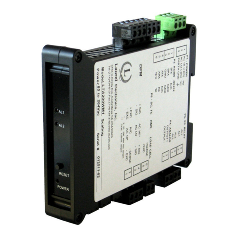
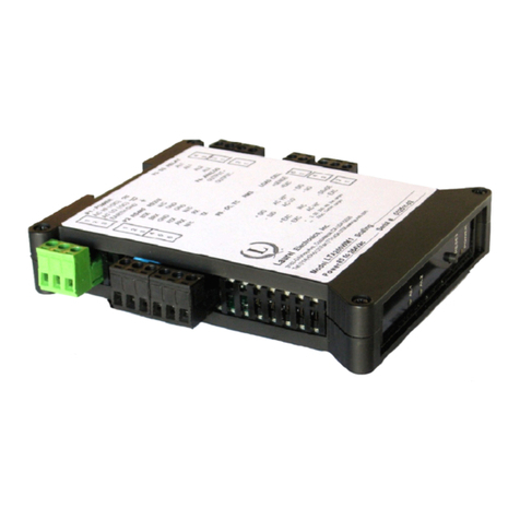
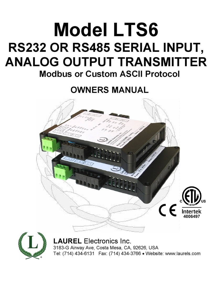
LAUREL LTS6 Series User manual

Model LTS6
RS232 OR RS485 SERIAL INPUT,
ANALOG OUTPUT TRANSMITTER
Modbus or Custo ASCII Protocol
OWNERS MANUAL
LAUREL Electronics Inc.
3183-G Airway Ave, Costa Mesa, CA, 92626, USA
el: (714) 434-6131 Fax: (714) 434-3766 • Website: www.laurels.com

- 2 -
1. ORDERING GUIDE, SERIAL INPUT TRANSMITTER
Configure a model number in this format: LTS60, CBL04
LTS
6
…Transmitter with 4-20 mA, 0-20 mA,
0-10V
or
-10V
to
+10V isolated analog
out ut, RS232 or RS485 serial data
in ut, and dual 120 mA solid state
relays. Default jum ered for RS232.
LTSE6E… Transmitter with 4-20 mA, 0-20
mA, 0-10V or -10V to +10V isolated
analog out ut, Ethernet serial data
in ut, and dual 120 mA solid state
relays.
Power
0............................. 85-264 Vac or 90-300 Vdc
1................................. 12-30 Vac or 10-
48 Vdc
ACCESSORIES
CBL04……RS232 cable, two 3- in connec-
tors on transmitter end, DB9
connector on com uter end.
CBL02……USB to DB9 ada ter cable. Can
be used with CBL01 or CBL04.

- 3 -
2. TABLE OF CONTENTS
1. ORDERING GUIDE, SERIAL INPUT TRANSMITTER .......................................................... 2
2. TABLE OF CONTENTS ....................................................................................................... 3
3. INTRODUCTION, SERIAL INPUT TRANSMITTER .............................................................. 4
4. RECEIVING & UNPACKING YOUR TRANSMITTER ........................................................... 5
5. SAFETY CONSIDERATIONS .............................................................................................. 6
6. TRANSMITTER FIELD WIRING ......................................................................................... 7
7. JUMPER SETTINGS .......................................................................................................... 8
8. PROGRAMMING YOUR TRANSMITTER ............................................................................ 10
9. CUSTOM ASCII PROTOCOL TRANSMITTER COMMUNICATIONS .................................... 20
10. SPECIFICATIONS, SERIAL INPUT TRANSMITTER ............................................................ 23
11. WARRANTY ...................................................................................................................... 24

- 4 -
3. INTRODUCTION, RS232 OR RS485 SERIAL INPUT TRANSMITTER
The LTS6 seri l input to n log output tr nsmitter (or serial-to-analog converter) acce ts
numeric readings embedded in streaming RS232 or RS485 ASCII serial data, and converts
these to an isolated, scalable 4-20 mA, 0-20 mA, 0-10V or -10V to +10V analog out ut. The
LTS6 utilizes an LT counter transmitter board, but no signal conditioner board. The unit fits on
a 35 mm DIN rail and is only 22.5 mm (0.89") thick. It is normally owered by AC (85-264 Vac),
but can o tionally be owered by low voltage AC or DC, such as 24 Vdc. All electrical
connections are via detachable screw-clam lugs.
The current or volt ge tr nsmitter output is jum er selectable and is transformer isolated to
avoid ground loo s. Either out ut rovides 16-bit resolution of the out ut s an and is ultra-
linear to within one bit. The out ut is scaled to the serial in ut in software. Out ut accuracy is
±0.02% of s an.
Du l solid st te rel ys rated 120 mA at 140 Vac or 180 Vdc are standard. The relays can
res ond to the transmitted serial values or to transmitted control characters, which override the
internal set oints. The relays can also be controlled inde endently of the serial in ut by
a lying signals to control in uts 1 and 2.
Isol tion to 250V rms is rovided for ower, the serial data in ut, analog out ut, and relay
out uts. Isolation adds safety and avoids ossible ground loo s.
Seri l d t input selections are RS232, half-du lex RS485, or full-du lex RS485. Selection is
via jum ers and/or at the connector.
Tr nsmitter setup is via the unit’s serial ort using an external PC and Instrument Setu
software, which can be downloaded from our website at no charge. The required 3-wire
transmitter-to-PC interface RS232 cable (CBL04) is easy to build and is also available for
urchase.
The LTS6 is not plug nd pl y. The format of the strings being received must be known in
advance, including non- rinting control characters. If you do not know the format of your ASCII
data, contact tech su ort of the manufacturer of the sending device. Or use a terminal
emulator PC rogram, like HyperTermin l or Re lTerm, to view the received data on your PC.
The LTSE6 Ethernet input to n log output tr nsmitter acce ts streaming Ethernet data and
converts it to an isolated, scalable 4-20 mA, 0-20 mA, 0-10V or -10V to +10V analog out ut.
That transmitter is covered by a se arate user manual.

- 5 -
4. RECEIVING & UNPACKING YOUR TRANSMITTER
Your transmitter was carefully tested and ins ected rior to shi ment. Should the transmitter be
damaged in shi ment, notify the freight carrier immediately. In the event the transmitter is not
configured as ordered or is ino erable, return it to the lace of urchase for re air or re lacement.
Please include a detailed descri tion of the roblem.

- 6 -
5. SAFETY CONSIDERATIONS
W rning: Use of this transmitter in a manner other than s ecified may im air the rotection
of the device and subject the user to a hazard. Visually ins ect the unit for signs of damage. If the
unit is damaged, do not attem t to o erate.
C ution:
• This unit may be owered with AC (mains) from 85-264 Vac or 90-300 Vdc with the high
voltage ower su ly o tion, or 12-30 Vac or 10-48 Vdc with the low voltage ower su ly
o tion. Verify that the ro er ower o tion is installed for the ower to be used. This
transmitter has no AC (mains) switch. It will be in o eration as soon as ower is a lied.
• The 85-264 Vac or 90-300 Vdc mains connector (P1 Pins 1-3) is colored green to differentiate
it from other in ut and out ut connectors. The 12-30 Vac or 10-48 Vdc mains connector is
colored bl ck.
• The analog out ut is sourcing. Do not connect the 4-20 mA analog out ut to a load designed
to a ly 24 Vdc to a two-wire transmitter. A lying 24 Vdc will burn out the main board.
• To avoid dangers of electrocution and/or short circuit, do not attem t to o en the case while
the unit is under ower. However, signal wiring changes external to the case can be made
safely while the unit is under ower.
• To revent electrical or fire hazard, do not ex ose the transmitter to excessive moisture.
• Do not o erate the transmitter in the resence of flammable gases or fumes. Such an environ-
ment constitutes an ex losion hazard.
• Secure the transmitter to a 35 mm DIN rail.
Symbols used:
Caution (refer to accom anying
documents)
Caution, risk of electric shock.
Equi ment rotected throughout
by double insulation or reinforced
insulation.
Earth (ground) terminal.
Both direct and alternating current.
Oper ting environment:
• Class II (double insulated) equi ment
designed for use in Pollution degree 2.
PROVISION FOR COOLING
PROVISION FOR COOLINGPROVISION FOR COOLING
PROVISION FOR COOLING
AL 1
AL 2
RESET
POWER
AL 1
AL 2
RESET
POWER
AL 1
AL 2
RESET
POWER
AL 1
AL 2
RESET
POWER
AL 1
AL 2
RESET
POWER
To avoid overheating, mount transmitters
with ventilation holes at to and bottom.
Leave a minimum of 6 mm 1/4”
) between
transmitters, or force air with a fan.

- 7 -
6. TRANSMITTER FIELD WIRING

- 8 -
7. JUMPER SETTINGS
Seri l Sign l
Duplex
Jumpers
Termin tion Resistor*
RS485 Full None E6 a = Transmit
E6 c = Receive
Half E6 b + d** E6 c
RS232 Full None None
* The termination resistor jum er settings should only be selected if the transmitter is the last
device on an RS485 line longer than 200 feet (60 m).
** Or connect external BTX to BRX and ATX to ARX (same effect as internal jum ers).
To reset communic tions to 9600 baud, command mode, Custom ASCII rotocol, and Address 1,
lace a jum er at E1, cycle ower, remove the jum er, and restart the transmitter.
An log Output
J4 Pins
Jumpers
Current, 4-20 mA 1 Lo, 2 Hi E2 a + d
Voltage, 0-10V 1 Lo, 2 Hi E2 b + c
Voltage, -10V to +10V 3 Lo, 2 Hi E2 b + c
Excit tion Output
Jumpers
5V, 100 mA E3 a + c; E4 a
10V, 120 mA E3 a + c; E4 b
24V, 50 mA E3 b, E4 none
Notes:
Notes:Notes:
Notes: 1.
1.1.
1. Jum ers for 4-20 mA out ut are shaded. Jum er settings are for main board Rev J.
2.
2.2.
2. Attem ting to draw more than rated excitation out ut current will shut down the out ut.
3.
3.3.
3. The n log output is sourcing. Do not a ly an external voltage. A lying an external
voltage of 24 Vdc will burn out the transmitter main board.

- 9 -
WHEN TO CHANGE JUMPERS
Your transmitter case does not need to be o ened if jum ers have already been set by your
distributor. Otherwise you will need to o en the case and either set jum ers or verify that the
factory default jum ers ositions will meet your needs. Factory default jum er settings are for
RS232 in ut and 4-20 mA out ut.
HOW TO OPEN & CLOSE THE CASE
The two clamshell halves of the case are held together with a bolt and a nut at each of the four
corners. Use a Philli s screwdriver to remove the four bolts. The nut will then dro off, and the
clamshell halves will se arate. When closing the case, make sure that the ventilation grills are
ro erly aligned.
C ution: The nuts at each corner are not ca tive and are black. Take recautions
so that the nuts do not get lost.

- 10 -
8. PROGRAMMING YOUR TRANSMITTER
OVERVIEW
Serial in ut transmitters are rogrammed using a PC with an RS232 ort and Instrument Setu
(IS) software, which rovides a gra hical user interface. The software allows u loading, editing,
downloading and saving of setu data.
CONNECTING TO YOUR PC
Use a 3-wire RS232 cable (P/N CBL04) to connect your transmitter to the COM ort of your PC.
Download the file ISx_x_x.exe from our website and double-click on the file name. Click on
“Install Instrument Setu Software” and follow the rom ts. To launch IS software, ress on
Start => Programs => IS2 => Instrument Setu or on the deskto icon that you may have
created. Following a brief s lash screen, the Communications Setu screen will a ear.
ESTABLISHING COMMUNICATIONS
In the Communications Setu screen, select Custom ASCII as the Protocol, as this is the
factory default setting. Select Transmitter LT as the Device Ty e. Then click on the RS-232
(USB) button. In the resulting Establish Communications screen, select your Com Port and

- 11 -
9600 as the Baud Rate. You will be able to change your rotocol and baud rate later under the
Communication setu tab. Click on Establish, and the two fields at the bottom of the screen
should turn green and dis lay your communication arameters and the counter-transmitter
revision level. Click on Main Menu. The com uter will remember your communication settings
for the next time that you run IS software.
The best way to learn IS software is to ex eriment with it. From the Main Menu, click on
Counter => Get Setu to retrieve (or get) the existing setu data from your counter-transmitter.
Click on View => Setu to bring u screens which allow you to easily edit the setu file using
ull-down menus and other selection tools. You can download (or ut) your edited file into the
transmitter by clicking on Counter => Put Setu . You can save your setu file to disk by clicking
on File => Save Setu and retrieve a reviously saved file from disk by click on File => O en.
After selecting a screen in ut field, ressing the F1 key will bring u detailed hel information
for that field.
Note the LTS6 serial-to-analog converter needs to receive continuous streaming serial data,
which can be RS232 or RS485. It cannot issue request commands.

- 12 -
SETTING UP BASIC OPERATION
Set Sign l input to None. Set Time Out to 000.00 Secs if you want the analog out ut to be held
indefinitely in the absence of a new serial in ut, or s ecify another time in seconds. Ignore
Signal In ut, Gate Time, Filter and Power-On Total, as these arameters do not a ly to the
serial out ut transmitter.
Under Displ y, select one of the Remote o erating modes shown. These modes are further
ex lained under the “Custom ASCII Protocol Transmitter Communications” section of this
manual. In the modes below:
Remote A = Addressable remote dis lay mode for string *#LSDDDD.DDA<CR><LF>, where * is
the recognition character, # is the address, L is a command character which can be H, K or L, S
is sign (s ace or + for ositive, - for negative), D is a digit from 0 to 9, A is an o tional alarm
character which overrides internal alarm com arisons, <CR> is the carriage return character,
and <LF> is an o tional line-feed character, which is ignored. The following modes are
available:
Remote S = Single value, non-addressable remote dis lay for SDDDD.DDA<CR> <LF>
Remote 1 = 1st value of value sequence SDDDD.DDSDDDD.DDSDDDD.DDSDDDD.DD
Remote 2 = 2nd value of value sequence SDDDD.DDSDDDD.DDSDDDD.DDSDDDD.DD
Remote 3 = 3rd value of value sequence SDDDD.DDSDDDD.DDSDDDD.DDSDDDD.DD
Remote 4 = 4th value of value sequence SDDDD.DDSDDDD.DDSDDDD.DDSDDDD.DD

- 13 -
Remote 1-4 allow multi le value to be extracted from Laureate transmissions. Data sequences
with u to three data values can be generated by Laureate digital anel meters and transmitters
(current reading, Peak, Valley). Data sequences with u to four data values can be generated by
Laureate counters (Items 1, 2, 3, Peak). Please refer to our DPM and counter manuals.
Remote C = Masked remote dis lay. Allows data extraction from a long string as s ecified
under the Communication tab. The required data entry fields will only a ear under the
Communication tab if Dis lay Ty e has been s ecified as Remote C under the In ut+Scaling
tab. Works only with the Custom ASCII rotocol, not the Modbus rotocol, since a transmitter
cannot listen to commands while in the Remote C dis lay ty e. For more information on
Remote C, see the manual section for the Communication tab.
After you have entered all settings in Instrument Setu Software, click on the Main Menu
button. Click on the Counter tab and do a Put Setu . This will download your setu from the PC
into the LTS6. Then exit Instrument Setu Software com letely and disconnect your LTS6.
The Control Inputs pull-down menu controls the effect of grounding Control In ut 1, Control
In ut 2, or both. Selections a licable to the serial in ut transmitter are the following:
• Meter Reset, Function Reset, Meter Reset (first row). When this row is selected,
grounding Control In ut 2 (causes a function reset, which resets latched alarms.
• Activ te Al rm 1, Activ te Al rm 2, Activ te Al rm 1&2. When this row is selected,
grounding Control In ut 1 activates relay 1, grounding Control In ut 2 activates relay 2, and
grounding both in uts activates Alarms 1 & 2.
• T re En ble, T re if En bled, T re (last row). When this row is selected, grounding Control
In ut 1 (normally with a ermanent connection) enables the Tare function. Momentarily
grounding Control In ut 2 stores the current digital value as an offset and subtracts this
offset from the digital reading sent to the transmitter, resulting in a zero value for alarms and
the analog out ut. This offset will also be subtracted from all new readings sent to the
transmitter. To change the offset, momentarily ground Control In ut 2 for the new in ut.
REMOTE C WARNING:
Do not execute a Main Menu > Counter > Get Setu command if you have laced the
transmitter into the Remote C mode, since that mode does not su ort Instrument Setu
communications. Instrument Setu Software will reset the transmitter to Remote A so that
it can retrieve setu information from the transmitter. Reconnecting the LTS6 to a PC and
using Instrument Setu Software, for exam le to check on reviously rogrammed
settings, will also take the LTS6 out of Remote C back into the Remote A. In that case, you
will need to reset the LTS6 to Remote C and do a Put Setu to re-download your setu
into the LTS6.

- 14 -
SETTING UP COMMUNICATIONS (REMOTE A & S MODES)
The above screen will a ear under the Communication tab if Remote A or Remote S has been
selected as Dis lay Ty e under the In ut+Dis lay tab. These two modes are not able to extract
data from an ASCII string that contains multi le data values and non-numeric characters.
Under this tab, you can reselect your Baud Rate, Device Address, Serial Protocol, and Full/Half
Du lex, even though you may have selected different values to establish initial communications
with your PC.
Set Out ut Mode to Command. Ignore the setting for CR(LF), Out ut Items, Out ut Filter, and
Out ut Rate, as these items a ly to digital transmission by a counter-transmitter, not to
digital-to-analog conversion by the serial in ut transmitter.

- 15 -
SETTING UP COMMUNICATIONS (REMOTE C MODE)
The above screen will a ear under the
Communication tab if Remote C has
been selected as Dis lay Ty e under the
In ut+Dis lay tab. This mode is able to
extract data from ASCII strings that
contain multi le data values and non-
numeric characters. Please see the F1
Hel screen to the right.
Under this tab, you can reselect Baud
Rate, Device Address, Serial Protocol,
and Full/Half Du lex, even though you
may have selected different values to es-
tablish initial communications with your PC.
Set Out ut Mode to Command. Ignore CR(LF), Out ut Items, Out ut Filter and Out ut Rate, as
these items a ly to digital transmission by a counter-transmitter, not to digital-to-analog
conversion by the serial in ut transmitter.
The number of characters shown can be u to 7, including 6 digits and a decimal oint. Include
leading zeros, such as 00300.0

- 16 -
SETTING UP THE ANALOG OUTPUT
Under the Analog Out tab, set Source to Item 3. Under Range, select 0-20 mA, 4-20 mA, 0-10V
or -10V to +10V as your desired analog out ut. Enter your Lo Range Reading and Hi Range
Reading. These will create the two end oint values of your analog out ut range. Only enter the
numerical values. The decimal oint is ignored. The s an between the two values should be at
least 256 counts to minimize the size of analog out ut ste s.

- 17 -
SETTING UP RELAY ALARMS OPERATION
Du l AC/DC solid st te rel ys rated 120 mA are standard for alarm or set oint control and are
inde endently set u via the “Relay Alarms” tab. Set “Alarm Source” to “Item 3” as illustrated.
For online hel with any data entry field, ress the F1 key.
• Setpoint. The number to which the current reading is com ared if deviation is set to zero. The
reading is the count in engineering units that is transmitted digitally and is also used for analog
out ut. For exam le, if the transmitted reading is in gallons/minute, the set oint will be
referenced to that reading, not to the raw ulse rate sent from a turbine flow meter.
ime
1000
Digital Reading
Setpoint
OFF OFF
ON
ime
1000 Setpoint OFF
ONON
Digital Reading
“Active High” On/Off setpoint control
with deviation =0
“Active Low” On/Off setpoint control
with deviation = 0

- 18 -
• Devi tion. A ositive number that can be added or subtracted from the set oint, de ending on
the Deviation Ty e, to determine when an alarm becomes Active or Inactive.
• Al rm Source. De ending on the Signal In ut Mode and Function selected under the In ut+
Dis lay tab, the alarm can be assigned to any of u to three Items, for exam le to Item 1
(A rate / B rate), Item 2 (A rate), or Item 3 (B rate).
• Al rm St te. If “Active High” is selected, the Active Alarm State is defined as being above the
set oint. If “Active Low” is selected, the Active Alarm State is defined as being below the
set oint. If “Disabled” is selected, the Alarm State is always inactive.
• Rel y St te. A setting with ties the Relay State to the Alarm State. If “Active On” is selected,
the relay will be closed when the Alarm State is 1. If “Active Off” is selected, the relay will be
o en when the Alarm State is 1.
• Devi tion Type. Three choices are offered: S lit Hysteresis, S an Hysteresis, and Band
Deviation. These define how Set oint and Deviation are to be combined to set Alarm State.
Span Hysteresis for heater control Band Deviation for co ponent testing
In Split Hysteresis, the relay o ens (or closes) when the reading goes above the Set oint lus
one Deviation, and closes (or o ens) when the reading falls below the Set oint less one
Deviation. Two Deviation limits lie symmetrically around the Set oint to create a deviation
band. A narrow hysteresis band is often used to minimize relay chatter. A wide band can be
used for on-off control.
In Sp n Hysteresis, o eration is as for S lit Hysteresis, exce t that the Set oint is always on
the high side, and a single Deviation lies below the Set oint to create the hysteresis band.
S an Hysteresis is considered by some to be more intuitive than S lit Hysteresis.
In B nd Devi tion, the relay o ens (or closes) when the reading falls within the deviation
band, and closes (or o ens) when the reading falls outside. Two deviation limits lie symmetric-
ally around the set oint to create the deviation band. Passbands around a set oint are often
used for go-no-go com onent testing.

- 19 -
• Al rm Type. Selections are Non-Latching and Latching. Under Non-Latching, the relay is only
closed (or o en) while the Alarm State is Active. Under Latching, the activated relay remains
closed (or o ens) until reset regardless of the Alarm State. Resetting is normally achieved by
tem orarily grounding one of the transmitter’s control in uts, which has been set to Function
Reset under the “In ut+Dis lay” tab.
• Al rms 1,2 No. Rdgs to Al rm. Selections are binary ste s from 1 to 128. This is the number
of consecutive alarm readings that must occur to create an Active alarm. Numbers higher than
2 rovide some Alarm filtering so that 1 or 2 noisy readings do not cause an Active Alarm. The
Alarm becomes Inactive if one of the consecutive readings fails to be an Alarm reading. The
Alarm readings counter then resets to 0.

- 20 -
9. CUSTOM ASCII PROTOCOL TRANSMITTER COMMUNICATIONS
All setu arameters are entered into the transmitter via Instrument Setu (IS) software,
including the serial communication format, digital address, o erating mode, analog out ut
scaling, and relay o erating modes and set oints.
1. SERIAL COMMUNICATION FORMAT
The Custom ASCII serial communication format for both RS232 and RS485 is the following:
Modes ............... Full Du lex (se arate transmit and receive lines) or Half Du lex (RS485 only).
Baud Rate ......... 300, 600, 1200, 2400, 4800, 9600, 19200 selectable with IS software.
Data Format ...... 8 data bits, no arity, 1 sto bit
2. DATA FORMAT
The basic in ut data format consists of 9 or 10 ASCII characters, such as +9999.99A<CR>. The
first character is always a lus or minus sign. There are 6 numeric digits. A decimal oint is
always required, even when it follows the last digit. The letter “A” is an o tional alarm
character. <CR> is the carriage return character. A line feed <LF> character at the end of the
string is ignored.
3. NETWORK CONFIGURATIONS
Using the Custom ASCII rotocol, serial in ut transmitters can o erate in a oint-to- oint mode
using RS232 or RS485, or in a multi- oint mode using RS485:
The point-to-point mode is a direct connection between a com uter (or other digital device)
and the transmitter. It is suggested that address 1 be selected for the oint-to- oint mode.
The multi-point mode is a connection from a host com uter to multi le transmitters bused
together with their in uts and out uts connected in arallel. It is necessary to set u each
device on the bus with a different address from 1 to 31. To write to a articular device, its
address is used in conjunction with the data, and only that device will res ond. The out uts of
all devices on the bus are set to a high im edance state, exce t the device being addressed.
Zero (0) is a s ecial address to which a device res onds only internally (e.g. Reset), but it does
not transmit any res onse on the out ut lines. All devices may be written to simultaneously
with a 0 address, and there will not be any out ut res onse contention.
4. OPERATING MODES
The serial in ut transmitter has multi le serial in ut modes, which are dedicated to the analog
out ut and relays based on serial data received via RS232 or RS485:
Remote A is an addressable in ut mode (u to 31 units) that uses the K command letter. It can
convert remote data on one or more transmitters having the command address in a multi- oint
or oint-to- oint configuration.
Other manuals for LTS6 Series
1
This manual suits for next models
2
Table of contents
Other LAUREL Transmitter manuals