Lauterbach C5000 Debugger User manual

MANUAL
Release 02.2022
C5000 Debugger

C5000 Debugger | 2
©1989-2022 Lauterbach
C5000 Debugger
TRACE32 Online Help
TRACE32 Directory
TRACE32 Index
TRACE32 Documents ......................................................................................................................
ICD In-Circuit Debugger ................................................................................................................
Processor Architecture Manuals ..............................................................................................
TI DSPs .....................................................................................................................................
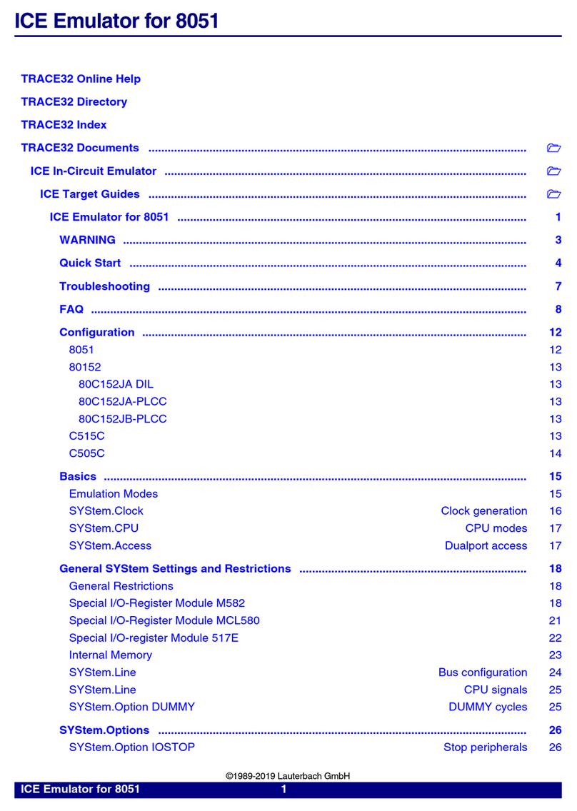
C5000 Debugger ................................................................................................................... 1
Brief Overview of Documents for New Users ................................................................. 5
Converter from GEL to PRACTICE .................................................................................. 5
Warning .............................................................................................................................. 6
DSP specific Implementations ......................................................................................... 7
Trigger 7
Breakpoints 7
Software Breakpoints 7
On-chip Breakpoints for Instructions 7
On-chip Breakpoints for Data 7
Memory Classes 8
DSP specific SYStem Commands ...................................................................................9
SYStem.Option.IMASKASM Disable interrupts while single stepping 9
SYStem.Option.IMASKHLL Disable interrupts while HLL single stepping 9
SYStem.CPU Select the used CPU 9
SYStem.JtagClock Define JTAG frequency 10
SYStem.MemAccess Run-time memory access 11
SYStem.Mode Establish the communication with the target 12
SYStem.CONFIG.state Display target configuration 13
SYStem.CONFIG Configure debugger according to target topology 15
<parameters> describing the “DebugPort” 20
<parameters> describing the “JTAG” scan chain and signal behavior 23
<parameters> describing a system level TAP “MultiTap” 27
<parameters> configuring a CoreSight Debug Access Port “AP” 29
<parameters> describing debug and trace “Components” 35
<parameters> which are “Deprecated” 44
SYStem.Option.AHBHPROT Select AHB-AP HPROT bits 48
SYStem.Option.AXIACEEnable ACE enable flag of the AXI-AP 48
SYStem.Option.AXICACHEFLAGS Configure AXI-AP cache bits 48

C5000 Debugger | 3
©1989-2022 Lauterbach
SYStem.Option.AXIHPROT Select AXI-AP HPROT bits 49
SYStem.Option.ByteMode Define byte mode 49
SYStem.Option.DAPDBGPWRUPREQ Force debug power in DAP 49
SYStem.Option.DAPSYSPWRUPREQ Force system power in DAP 50
SYStem.Option.DAPREMAP Rearrange DAP memory map 51
SYStem.Option.DEBUGPORTOptions Options for debug port handling 51
SYStem.Option.DAPNOIRCHECK No DAP instruction register check 52
SYStem.Option.DUALPORT Implicitly use run-time memory access 53
SYStem.Option.EnReset Allow the debugger to drive nRESET (nSRST) 53
SYStem.LOCK Tristate the JTAG port 53
SYStem.Option.EnTRST Control TAP reset 54
SYStem.Option.INTDIS Disable all interrupts 54
SYStem.Option.MUHP High-priority memory access 54
SYStem.Option.OVERLAY Enable overlay support 55
SYStem.Option.PWRDWN Allow power-down mode 55
SYStem.Option.TargetServer Use target server from TI 56
SYStem.Option.TURBO Use DMA for write accesses 56
SYStem.RESetOut Reset the DSP 56
SYStem.Option.CToolsDecoder Use TI’s trace decoder software 57
SYStem.Option.CtoolsNoSync CToolsNoSync 57
CPU specific BenchMarkCounter Commands ................................................................ 58
BMC.<counter>.ATOB Advise counter to count within AB-range 58
BMC.<counter>.EVENT Assign event to counter 59
TrOnchip Commands ........................................................................................................ 60
TrOnchip.state Display on-chip trigger window 60
TrOnchip.CONVert Adjust range breakpoint in on-chip resource 60
C55X specific TrOnchip Commands ............................................................................... 61
TrOnchip.ATOB Activate on-chip breakpoints in AB-range 61
TrOnchip.BMCTR Configure the benchmark counter 61
TrOnchip.CLOCK Set the clock for the benchmark counter 65
TrOnchip.CoefficientAccess AET trigger optimization 65
TrOnchip.DualAccess AET trigger optimization 65
TrOnchip.PROfile Display the benchmark data 65
TrOnchip.RESet Set on-chip trigger to default state 66
Tracing ............................................................................................................................... 67
Controlling the Trace Capture 67
Trace Breakpoints 67
JTAG Connection .............................................................................................................. 68
Mechanical Description of the 20-pin Debug Cable 68
Electrical Description of the 20-pin Debug Cable 69
Mechanical Description of the 14-pin Debug Cable 70
Electrical Description of the 14-pin Debug Cable 70

C5000 Debugger | 4
©1989-2022 Lauterbach
Mechanical Description of the TI Connector 71
FAQ ..................................................................................................................................... 71
Operation Voltage ............................................................................................................. 72

C5000 Debugger | 5
©1989-2022 Lauterbach
C5000 Debugger
Version 09-Mar-2022
Brief Overview of Documents for New Users
Architecture-independent information:
•“Training - Debugger Basics” (training_debugger.pdf): Get familiar with the basic features of a
TRACE32 debugger.
•“T32Start” (app_t32start.pdf): T32Start assists you in starting TRACE32 PowerView instances
for different configurations of the debugger. T32Start is only available for Windows.
•“General Commands” (general_ref_<x>.pdf): Alphabetic list of debug commands.
Architecture-specific information:
•“Processor Architecture Manuals”: These manuals describe commands that are specific for the
processor architecture supported by your debug cable. To access the manual for your processor
architecture, proceed as follows:
- Choose Help menu > Processor Architecture Manual.
•“OS Awareness Manuals” (rtos_<os>.pdf): TRACE32 PowerView can be extended for operating
system-aware debugging. The appropriate OS Awareness manual informs you how to enable the
OS-aware debugging.
Converter from GEL to PRACTICE
The General Extension Language (GEL) is an interpretive language similar to C that lets you create
functions to extend Code Composer Studio’s usefulness. The converter allows you to convert GEL language
into PRACTICE scripts (*.cmm), which can be used directly in TRACE32.
For more detailed information on that converter please refer to “Converter from GEL to PRACTICE”
(converter_gel.pdf).

C5000 Debugger | 6
©1989-2022 Lauterbach
Warning
WARNING: To prevent debugger and target from damage it is recommended to connect or
disconnect the Debug Cable only while the target power is OFF.
Recommendation for the software start:
1. Disconnect the Debug Cable from the target while the target power is
off.
2. Connect the host system, the TRACE32 hardware and the Debug
Cable.
3. Power ON the TRACE32 hardware.
4. Start the TRACE32 software to load the debugger firmware.
5. Connect the Debug Cable to the target.
6. Switch the target power ON.
7. Configure your debugger e.g. via a start-up script.
Power down:
1. Switch off the target power.
2. Disconnect the Debug Cable from the target.
3. Close the TRACE32 software.
4. Power OFF the TRACE32 hardware.

C5000 Debugger | 7
©1989-2022 Lauterbach
DSP specific Implementations
Trigger
A bidirectional trigger system allows the following two events:
• Trigger an external system (e.g. logic analyzer) if the program execution is stopped.
• Stop the program execution if an external trigger is asserted.
For more information refer to the TrBus command.
Breakpoints
Software Breakpoints
If a software breakpoint is used, the original code at the breakpoint location is temporarily patched by a
breakpoint code. There is no restriction in the number of software breakpoints.
On-chip Breakpoints for Instructions
If on-chip breakpoints are used, the resources to set the breakpoints are provided by the CPU. Those CPU
resources only allow to set single address instruction breakpoints.
On-chip Breakpoints for Data
To stop the CPU after a read or write access to a memory location on-chip breakpoints are required. In the
DSP notation these breakpoints are called watch points (WP).
Overview
•On-chip breakpoints: Total amount of available on-chip breakpoints.
•Instruction breakpoints: Number of on-chip breakpoints that can be used to set program
breakpoints into ROM/FLASH/EPROM.
•Read/Write breakpoints: Number of on-chip breakpoints that can be used as Read or Write
breakpoints.
•Data Value breakpoint: Number of on-chip data breakpoints that can be used to stop the
program when a specific data value is written to an address or when a specific data value is read
from an address.

C5000 Debugger | 8
©1989-2022 Lauterbach
Memory Classes
The following DSP specific memory classes are available.
To access a memory class, write the class in front of the address.
Example:
Core
On-chip
breakpoints
Instruction
breakpoints
Read/Write
breakpoint
Data Value
breakpoints
C54x 2 2 single address — —
C55x 4 up to 4 single
address
up to 3 data,
1 breakpoint
range and 2 bit
masks
up to 3
Memory Class Description
P Program Memory
D Data Memory
IO Input/Output Area
VM Virtual Memory (memory on the debug system)
E Emulation Memory, Pseudo Dualport Access to Memory
(see SYStem.CpuAccess)
Data.dump IO:0- -3

C5000 Debugger | 9
©1989-2022 Lauterbach
DSP specific SYStem Commands
SYStem.Option.IMASKASM Disable interrupts while single stepping
Default: OFF.
Interrupts are disabled during an assembler single-step operations, if this option is "ON".
SYStem.Option.IMASKHLL Disable interrupts while HLL single stepping
Default: OFF.
Interrupts are disabled during HLL single-step operations, if this option is "ON".
SYStem.CPU Select the used CPU
Default selection: C55XX. Selects the processor type. If your ASIC is not listed, select the type of the
integrated DSP core.
Format: SYStem.Option.IMASKASM [ON | OFF]
Format: SYStem.Option.IMASKHLL [ON | OFF]
Format: SYStem.CPU <cpu>
<cpu>:C55XX | C5510 | OMAP1510 | OMAP1610 | LEAD3PH2 | LEAD3PH3 | …

C5000 Debugger | 10
©1989-2022 Lauterbach
SYStem.JtagClock Define JTAG frequency
Default frequency: 10 MHz.
Selects the JTAG port frequency (TCK) used by the debugger to communicate with the processor. The
frequency affects e.g. the download speed. It could be required to reduce the JTAG frequency if there are
buffers, additional loads or high capacities on the JTAG lines or if VTREF is very low. A very high frequency
will not work on all systems and will result in an erroneous data transfer. Therefore we recommend to use
the default setting if possible.
Format: SYStem.JtagClock [<frequency> | RTCK | RTCK <frequency>] |
ARTCK <frequency>]
<frequency>:10000. … 80000000.
<frequency> The debugger cannot select all frequencies accurately. It chooses the
next possible frequency and displays the real value in the "System
Settings" window.
Besides a decimal number like "100000." short forms like "10kHz" or
"15MHz" can also be used. The short forms imply a decimal value,
although no"." is used.
RTCK The JTAG clock is controlled by the RTCK signal (Returned TCK).
On some processor derivatives including an ARM core (e.g. OMAP)
there is the need to synchronize the processor clock and the JTAG clock.
In this case RTCK shall be selected. Synchronization is maintained,
because the debugger does not progress to the next TCK edge until after
an RTCK edge is received.
When RTCK is selected, the maximum reachable frequency is limited to
10 MHz. This limit can be changed by adding the frequency parameter. A
limitation is required that the JTAG clock speed can not become higher
than the physical interface can manage.
Example: SYStem.JtagClock RTCK 20MHz
ARTCK Accelerated method to control the JTAG clock by the RTCK signal
(Accelerated Returned TCK).
RTCK mode allows theoretical frequencies up to 1/6 of the processor
clock. For designs using a very low processor clock we offer a different
mode (ARTCK) which does not work as recommended by ARM and
might not work on all target systems. In ARTCK mode the debugger uses
a fixed JTAG frequency for TCK, independent of the RTCK signal. This
frequency must be specified by the user and has to be below 1/2 of the
processor clock speed. The signal RTCK clocks TDI and TMS and
controls the sampling of TDO.

C5000 Debugger | 11
©1989-2022 Lauterbach
SYStem.MemAccess Run-time memory access
Default: Denied.
CTCK With this option higher debug port speeds can be reached. The
TDO/SWDIO signal will be sampled by a signal which derives from
TCK/SWCLK, but which is timely compensated regarding the debugger-
internal driver propagation delays (Compensation by TCK). This feature
can be used with a debug cable version 3 or newer. If it is selected,
although the debug cable is not suitable, a fixed frequency will be
selected instead (minimum of 10 MHz and selected clock).
CRTCK With this option higher debug port speeds can be reached. The
TDO/SWDIO signal will be sampled by the RTCK signal. This compensates
the debugger-internal driver propagation delays, the delays on the cable and
on the target (Compensation by RTCK). This feature requires that the target
provides an RTCK signal. In contrast to the RTCK option, the TCK/SWCLK
is always output with the selected, fixed frequency.
Format: SYStem.MemAccess <mode>
<mode>: Enable
Denied
StopAndGo
Enable
CPU (deprecated)
Access is made without CPU intervention. This is only possible on the
instruction set simulator.
StopAndGo Temporarily halts the core(s) to perform the memory access. Each stop
takes some time depending on the speed of the JTAG port, the number of
the assigned cores, and the operations that should be performed. For
more information, see below.
Denied No memory access is possible without stopping the CPU.

C5000 Debugger | 12
©1989-2022 Lauterbach
SYStem.Mode Establish the communication with the target
Default: Down.
Configures how the debugger connects to the target and how the target is handled.
Format: SYStem.Mode <mode>
SYStem.Attach (alias for SYStem.Mode Attach)
SYStem.Down (alias for SYStem.Mode Down)
SYStem.Up (alias for SYStem.Mode Up)
<mode>:Down
NoDebug
Prepare
Go
Attach
StandBy
Up
Down Disables the debugger. The state of the CPU remains unchanged. The
JTAG port is tristated.
NoDebug Disables the debugger. The state of the CPU remains unchanged. The
JTAG port is tristated.
Prepare The debugger initializes the debug port (JTAG, SWD, cJTAG) and
CoreSight DAP interface, but does not connect to the CPU.
This debug mode is used if the CPU shall not be debugged or bypassed,
i.e. the debugger can access the memory busses, such as AXI, AHB and
APB, directly through the memory access ports of the CoreSight DAP.
Typical use cases:
• The debugger accesses (physical) memory and bypasses the CPU
if a mapping exists. Memory might require initialization before it can
be accessed.
• The debugger accesses peripherals, e.g. for configuring registers
prior to stopping the CPU in debug mode. Peripherals might need to
be clocked and powered before they can be accessed.
• Third-party software or proprietary debuggers use the TRACE32
API (application programming interface) to access the debug port
and DAP via the TRACE32 debugger hardware.
Go Resets the target via the reset line, initializes the debug port (JTAG, SWD,
cJTAG), and starts the program execution. For a reset, the reset line has to
be connected to the debug connector.
Program execution can, for example, be stopped by the Break command.

C5000 Debugger | 13
©1989-2022 Lauterbach
SYStem.CONFIG.state Display target configuration
Opens the SYStem.CONFIG.state window, where you can view and modify most of the target
configuration settings. The configuration settings tell the debugger how to communicate with the chip on
the target board and how to access the on-chip debug and trace facilities in order to accomplish the
debugger’s operations.
Alternatively, you can modify the target configuration settings via the TRACE32 command line with the
SYStem.CONFIG commands. Note that the command line provides additional SYStem.CONFIG
commands for settings that are not included in the SYStem.CONFIG.state window.
Attach No reset happens, the mode of the core (running or halted) does not
change. The debug port (JTAG, SWD, cJTAG) will be initialized.
After this command has been executed, the user program can, for
example, be stopped with the Break command.
StandBy Keeps the target in reset via the reset line and waits until power is
detected. For a reset, the reset line has to be connected to the debug
connector.
Once power has been detected, the debugger restores as many debug
registers as possible (e.g. on-chip breakpoints, vector catch events, trace
control) and releases the CPU from reset to start the program execution.
When a CPU power-down is detected, the debugger switches
automatically back to the StandBy mode. This allows debugging of a
power cycle because debug registers will be restored on power-up.
NOTE: Usually only on-chip breakpoints and vector catch events can be
set while the CPU is running. To set a software breakpoint, the CPU has to
be stopped.
Up Resets the target via the reset line, initializes the debug port (JTAG, SWD,
cJTAG), stops the CPU, and enters debug mode.
For a reset, the reset line has to be connected to the debug connector.
The current state of all registers is read from the CPU.
Format: SYStem.CONFIG.state [/<tab>]
<tab>:DebugPort | Jtag | MultiTap | AccessPorts | COmponents

C5000 Debugger | 14
©1989-2022 Lauterbach
<tab> Opens the SYStem.CONFIG.state window on the specified tab. For tab
descriptions, see below.
DebugPort
(default)
The DebugPort tab informs the debugger about the debug connector
type and the communication protocol it shall use.
For descriptions of the commands on the DebugPort tab, see
DebugPort.
Jtag The Jtag tab informs the debugger about the position of the Test Access
Ports (TAP) in the JTAG chain which the debugger needs to talk to in
order to access the debug and trace facilities on the chip.
For descriptions of the commands on the Jtag tab, see Jtag.
MultiTap Informs the debugger about the existence and type of a System/Chip
Level Test Access Port. The debugger might need to control it in order to
reconfigure the JTAG chain or to control power, clock, reset, and security
of different chip components.
For descriptions of the commands on the MultiTap tab, see MultiTap.
AccessPorts This tab informs the debugger about an Arm CoreSight Access Port (AP)
and about how to control the AP to access chip-internal memory busses
(AHB, APB, AXI) or chip-internal JTAG interfaces.
For a descriptions of a corresponding commands, refer to AP.
COmponents The COmponents tab informs the debugger (a) about the existence and
interconnection of on-chip CoreSight debug and trace modules and (b)
informs the debugger on which memory bus and at which base address
the debugger can find the control registers of the modules.
For descriptions of the commands on the COmponents tab, see
COmponents.

C5000 Debugger | 15
©1989-2022 Lauterbach
SYStem.CONFIG Configure debugger according to target topology
Format: SYStem.CONFIG <parameter>
SYStem.MultiCore <parameter> (deprecated)
<parameter>:
(DebugPort)
CJTAGFLAGS <flags> (C7000 only)
CONNECTOR [MIPI34 | MIPI20T] (C7000 only)
CORE <core> <chip>
CoreNumber <number>
DEBUGPORT [DebugCable0 | DebugCableA | DebugCableB]
DEBUGPORTTYPE [JTAG | SWD | CJTAG | CJTAGSWD]
Slave [ON | OFF]
SWDP [ON | OFF] (C7000 only)
SWDPIdleHigh [ON | OFF]
SWDPTargetSel <value>
TriState [ON | OFF]
<parameter>:
(JTAG cont.)
DAPDRPOST <bits>
DAPDRPRE <bits>
DAPIRPOST <bits>
DAPIRPRE <bits>
DRPOST <bits>
DRPRE <bits>
ETBDRPOST <bits> (C5000 only)
ETBDRPRE <bits> (C5000 only)
ETBIRPOST<bits> (C5000 only)
ETBIRPRE <bits> (C5000 only)
<parameter>:
(JTAG cont.)
IRPOST<bits>
IRPRE <bits>
Slave [ON | OFF]
TAPState <state>
TCKLevel <level>
TriState [ON | OFF]
<parameter>:
(MultiTap)
DAPTAP <tap>
DEBUGTAP <tap>
ETBTAP <tap> (C5000 only)
MULTITAP [NONE |IcepickA |IcepickB |IcepickC |IcepickD |IcepickBB |
IcepickBC |IcepickCC |IcepickDD |
JtagSEQuence <sub_cmd>]
NJCR <tap>
SLAVETAP <tap>

C5000 Debugger | 16
©1989-2022 Lauterbach
<parameter>:
(AccessPorts
)
AHBAPn.Base <address>
AHBAPn.HPROT [<value> | <name>]
AHBAPn.Port <port>
AHBAPn.RESet
AHBAPn.view
AHBAPn.XtorName <name>
APBAPn.Base <address>
APBAPn.Port <port>
APBAPn.RESet
APBAPn.view
APBAPn.XtorName <name>
AXIAPn.ACEEnable [ON |OFF]
AXIAPn.Base <address>
AXIAPn.CacheFlags <value>
AXIAPn.HPROT [<value> | <name>]
AXIAPn.Port <port>
AXIAPn.RESet
AXIAPn.view
AXIAPn.XtorName <name>
DEBUGAPn.Port <port>
DEBUGAPn.RESet
DEBUGAPn.view
DEBUGAPn.XtorName <name>
JTAGAPn.Base <address>
JTAGAPn.Port <port>
JTAGAPn.CorePort <port>
JTAGAPn.RESet
JTAGAPn.view
JTAGAPn.XtorName <name>
<parameter>:
(AccessPorts
cont.)
MEMORYAPn.HPROT [<value> | <name>]
MEMORYAPn.Port <port>
MEMORYAPn.RESet
MEMORYAPn.view
MEMORYAPn.XtorName <name>
<parameter>:
(COmponents)
ADTF.Base <address>
ADTF.RESet
ADTF.Type [NONE |ADTF |ADTF2 |GEM]
ADTF.view
AET.Base <address> (C5000, C6000, C7000 only)
AET.RESet (C5000, C6000, C7000 only)
AET.view (C5000, C6000, C7000 only)

C5000 Debugger | 17
©1989-2022 Lauterbach
<parameter>:
(COmponents
cont.)
CMI.Base <address>
CMI.RESet
CMI.TraceID <id>
CMI.view
COREDEBUG.Base <address> (C7000 only)
COREDEBUG.RESet (C7000 only)
COREDEBUG.view (C7000 only)
CTI.Base <address>
CTI.Config [NONE | ARMV1 | ARMPostInit | OMAP3 | TMS570 | CortexV1 |
QV1]
CTI.RESet
CTI.view
DRM.Base <address>
DRM.RESet
DRM.view
EPM.Base <address>
EPM.RESet
EPM.view
ETB.ATBSource <source>
ETB.Base <address>
ETB.Name <string>
ETB.NoFlush [ON | OFF]
ETB.RESet
ETB.Size <size>
ETB.STackMode [NotAvailbale | TRGETM | FULLTIDRM | NOTSET | FULL-
STOP | FULLCTI]
ETB.view
<parameter>:
(COmponents
cont.)
FUNNEL.ATBSource <sourcelist>
FUNNEL.Base <address>
FUNNEL.Name <string>
FUNNEL.PROGrammable [ON | OFF]
FUNNEL.RESet
FUNNEL.view
OCP.Base <address>
OCP.RESet
OCP.TraceID <id>
OCP.view
PMI.Base <address>
PMI.RESet
PMI.TraceID <id>
PMI.view

C5000 Debugger | 18
©1989-2022 Lauterbach
<parameter>:
(Components
cont.)
REP.ATBSource <source>
REP.Base <address>
REP.Name <string>
REP.RESet
REP.view
SC.Base <address>
SC.RESet
SC.TraceID <id>
SC.view
STM.Base <address>
STM.Mode [None | SDTI | STP | STP64 | STPv2 | STPv2LE]
STM.Name <string>
STM.RESet
STM.Type [None | GenericARM | SDTI | TI]
STM.view
TBR.ATBSource <source>
TBR.Base <address>
TBR.Name <string>
TBR.NoFlush [ON | OFF]
TBR.RESet
TBR.STackMode [NotAvailbale | TRGETM | FULLTIDRM | NOTSET | FULL-
STOP | FULLCTI]
TBR.view
TPIU.ATBSource <source>
TPIU.Base <address>
TPIU.Name <string>
TPIU.RESet
TPIU.Type [CoreSight | Generic]
TPIU.view
<parameter>:
(Components
cont.)
TRACEPORT.Name
TRACEPORT.RESet
TRACEPORT.TraceSource
TRACEPORT.Type
TRACEPORT.view
TRC.Base <address> (C7000 only)
TRC.RESet (C7000 only)
TRC.view (C7000 only)
<parameter>:
(Deprecated)
COREBASE <address>
CTIBASE <address>
DEBUGBASE <address>
ETBBASE <address>
ETBFUNNELBASE <address>
ETFBASE <address>
ETMBASE <address>

C5000 Debugger | 19
©1989-2022 Lauterbach
The SYStem.CONFIG commands inform the debugger about the available on-chip debug and trace
components and how to access them.
This is a common description of the SYStem.CONFIG command group for the TI C2000, C5000, C6000
and C7000 DSPs. Each debugger will provide only a subset of these commands. Some commands need a
certain CPU type selection (SYStem.CPU <type>) to become active and it might additionally depend on
further settings.
Ideally you can select with SYStem.CPU the chip you are using which causes all setup you need and you do
not need any further SYStem.CONFIG command.
The SYStem.CONFIG command information shall be provided after the SYStem.CPU command, which
might be a precondition to enter certain SYStem.CONFIG commands, and before you start up the debug
session e.g. by SYStem.Up.
<parameter>:
(Deprecated cont.)
FUNNEL2BASE <address>
FUNNELBASE <address>
HTMBASE <address>
ITMBASE <address>
RTPBASE <address>
SDTIBASE <address>
STMBASE <address>
TIADTFBASE <address>
TIDRMBASE <address>
TIEPMBASE <address>
TIOCPBASE <address>
TIOCPTYPE <type>
TIPMIBASE <address>
TISCBASE <address>
TISTMBASE <address>
TPIUBASE <address>
TPIUFUNNELBASE <address>
TRACEETBFUNNELPORT <port>
TRACEFUNNELPORT<port>
TRACETPIUFUNNELPORT <port>
view
AHBACCESSPORT <port>
APBACCESSPORT <port>
AXIACCESSPORT <port>
COREJTAGPORT <port>
DEBUGACCESSPORT <port>
JTAGACCESSPORT <port>
MEMORYACCESSPORT <port>

C5000 Debugger | 20
©1989-2022 Lauterbach
<parameters> describing the “DebugPort”
CJTAGFLAGS <flags> Activates bug fixes for “cJTAG” implementations.
Bit 0: Disable scanning of cJTAG ID.
Bit 1: Target has no “keeper”.
Bit 2: Inverted meaning of SREDGE register.
Bit 3: Old command opcodes.
Bit 4: Unlock cJTAG via APFC register.
Default: 0
CONNECTOR
[MIPI34 | MIPI20T]
Specifies the connector “MIPI34” or “MIPI20T” on the target. This
is mainly needed in order to notify the trace pin location.
Default: MIPI34 if CombiProbe is used, MIPI20T if µTrace
(MicroTrace) is used.
CORE <core> <chip> The command helps to identify debug and trace resources which
are commonly used by different cores. The command might be
required in a multicore environment if you use multiple debugger
instances (multiple TRACE32 PowerView GUIs) to simultaneously
debug different cores on the same target system.
Because of the default setting of this command
debugger#1: <core>=1 <chip>=1
debugger#2: <core>=1 <chip>=2
...
each debugger instance assumes that all notified debug and trace
resources can exclusively be used.
But some target systems have shared resources for different
cores, for example a common trace port. The default setting
causes that each debugger instance controls the same trace port.
Sometimes it does not hurt if such a module is controlled twice.
But sometimes it is a must to tell the debugger that these cores
share resources on the same <chip>. Whereby the “chip” does not
need to be identical with the device on your target board:
debugger#1: <core>=1 <chip>=1
debugger#2: <core>=2 <chip>=1
Table of contents
Other Lauterbach Computer Hardware manuals
Popular Computer Hardware manuals by other brands
CNC4PC
CNC4PC C80 user manual
EK-Quantum
EK-Quantum Momentum2 ROG Strix X570-i Gaming D-RGB user guide
EK-Quantum
EK-Quantum Vector2 FTW3 RTX 3080 D-RGB manual
Hawking
Hawking HWC54DA Quick installation guide
Renesas
Renesas RA6 Series user manual
Avalue Technology
Avalue Technology ARC-21W34 Quick reference guide
