lavina 32R-S-E User manual

Superabrasive Owner’s Manual – Lavina® 32R-S-E 11/2014
1
LAVINA®32R -S-E User Manual
www.superabrasive.com / factory@superabrasive.com

Superabrasive Owner’s Manual – Lavina® 32R-S-E 11/2014
2
1.GENERALINFORMATION................................................3
Machinecharacteristics...........................................................................3
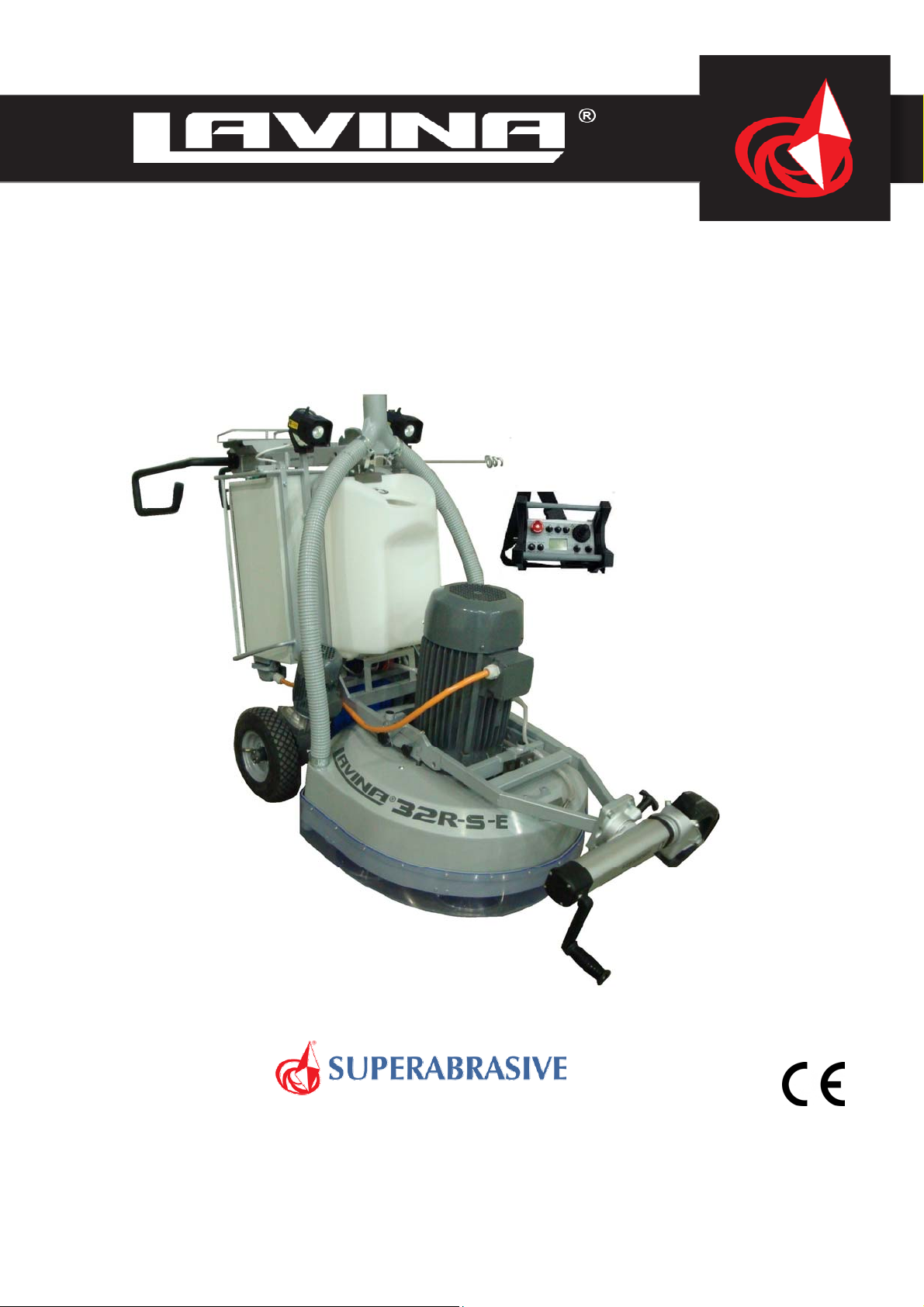
Lavina®32R‐S‐EMaindesign....................................................................3
EnvironmentalConditions........................................................................4
ElectricalConnection...............................................................................4
VacuumConnection.................................................................................4
TechnicalData..........................................................................................4
CE‐Certification........................................................................................4
Vibrations.................................................................................................4
SONOROUSEMISSIONS............................................................................4
LabelData................................................................................................4
CustomerService.....................................................................................4
2.SAFETYISTRUCTIONS......................................................5
RecommendedUse..................................................................................5
ProhibitedUse.........................................................................................5
Preparationforwork................................................................................5
ProtectionDevices...................................................................................5
ArrestFunctions.......................................................................................5
SafeUse...................................................................................................5
ResidualRisks...........................................................................................5
BeforeYouBegin......................................................................................5
OperatingMachine..................................................................................5
AfterWorkiscompleted..........................................................................5
TheWorkArea.........................................................................................5
PERSONALPROTECTIVEEquipment(ppe)................................................5
Operator..................................................................................................6
3.HANDLINGANDTRANSPORTATION................................6
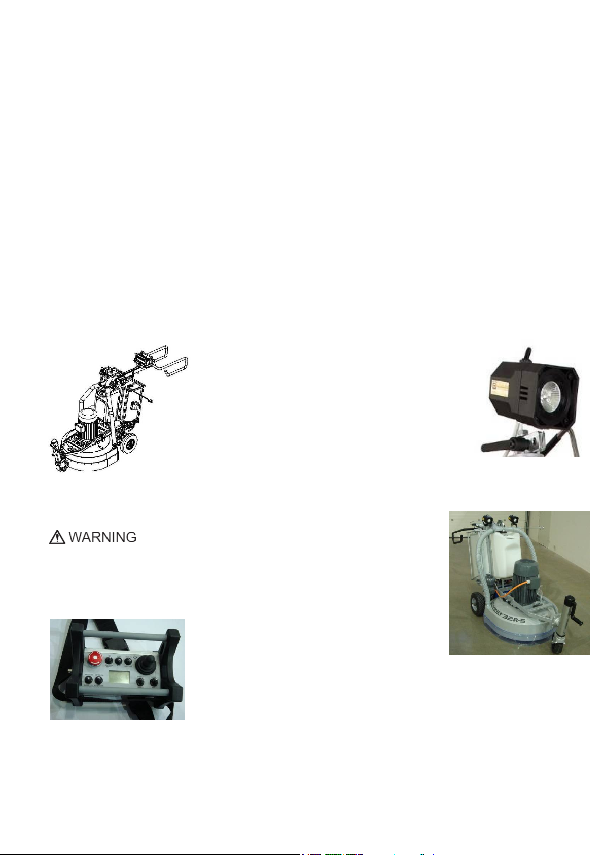
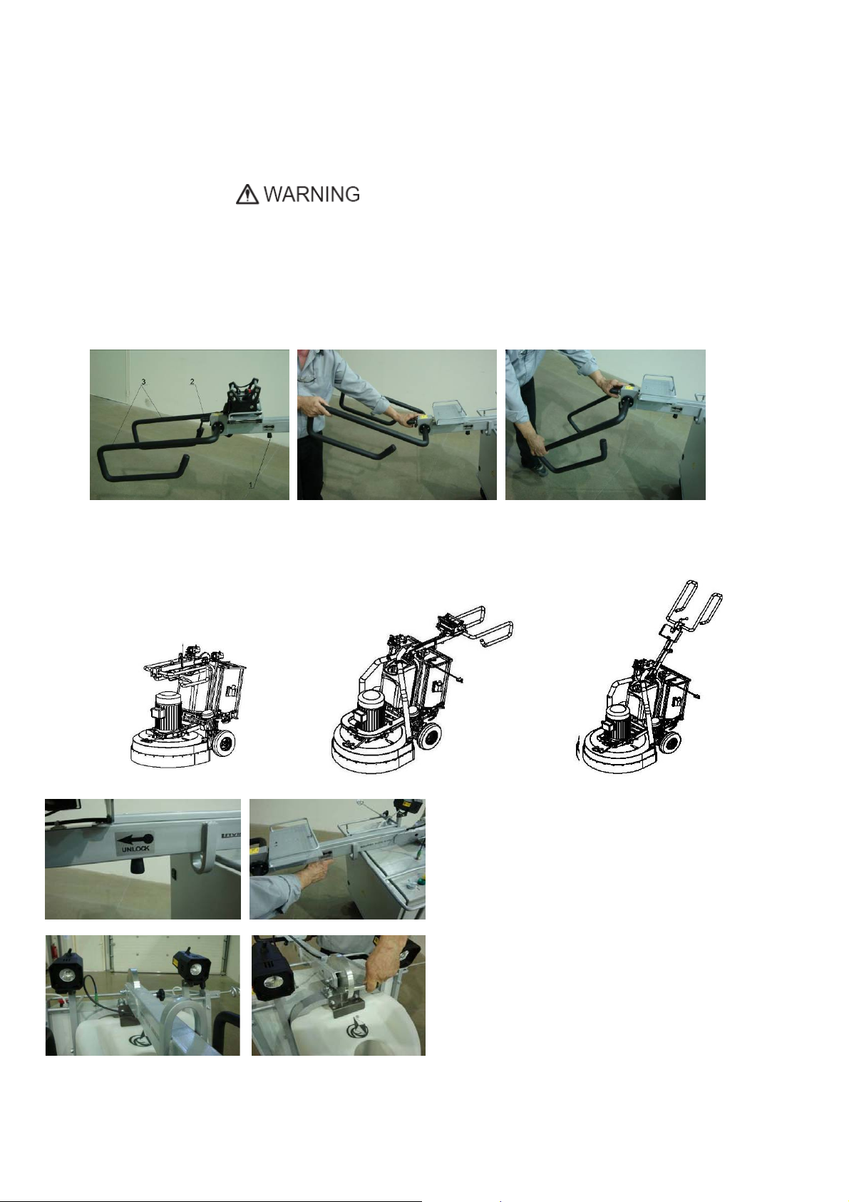
Positioningthehandle.............................................................................6
Flippingthemachineup...........................................................................7
Splittingthecarriagefromthemainhead...............................................7
Lifting.......................................................................................................7
Leadingpowercable................................................................................8
Thirdwheel..............................................................................................8
RELEASINGINGTHEWHEELSOFTHECARRIAGE......................................8
Storage.....................................................................................................8
4.OPERATION...................................................................10
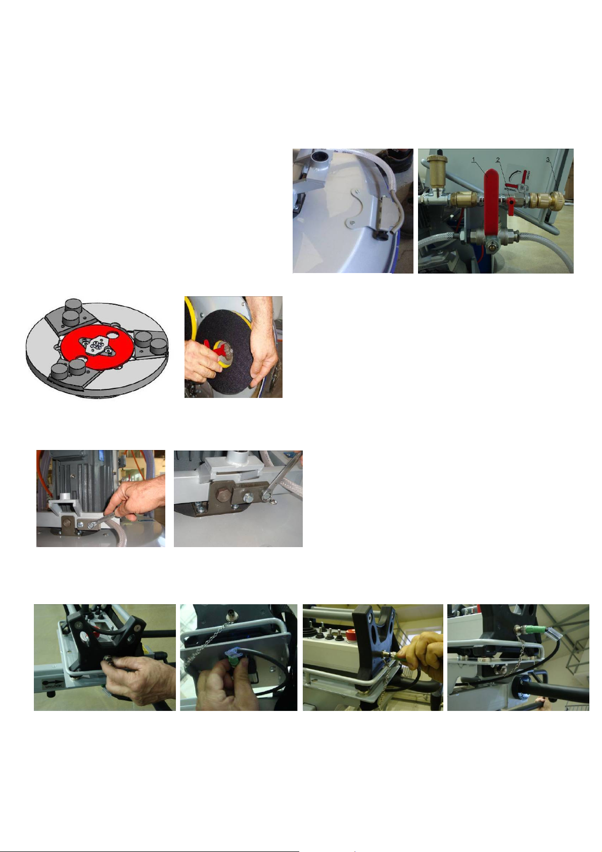
PreliminaryControls..............................................................................10
Controlofthewaterflow........................................................................10
AdjustingandMountingTools...............................................................10
FRAMEBLOCKING(u‐joint]....................................................................10
CONTROLPANEL....................................................................................10
OperatingtheMachine..........................................................................12
StoppingtheMachine............................................................................12
Alarm.....................................................................................................12
5.TOOLSANDACCESSORIES.............................................12
Weights..................................................................................................12
FoamPlate.............................................................................................12
SecurityplateforQuickchangepads......................................................12
6.POPULARTOOLS..........................................................13
7.EXPLODEDVIEW..........................................................14
GeneralExplodedView(fig.7.1)............................................................14
TOOLHOLDERFORMACHINESExplodedView(fig.7.2)........................14
BOTTOMCOVERASSEMBLYExplodedView(fig.7.3).............................14
PULLEYUNITExplodedView(fig.7.4)....................................................14
MOTORSUPPORTExplodedView(fig.7.5).............................................14
CENTRALSHAFTBEARINGExplodedView(fig.7.6)................................15
TopCoverExplodedView(fig.7.7).........................................................15
GUARDASSEMBLYExplodedView(fig.7.8)...........................................15
CarriageExplodedView(fig.7.9).............................................................15
STEERINGBRACKETExplodedView(fig.7.10).........................................15
ToolHolderExplodedView(fig.7.11).....................................................15
8.MAINTENANCEANDINSPECTION.................................16
Cleaning..................................................................................................16
CheckDaily.............................................................................................16
Checkafterthefirst15WorkingHours..................................................16
CheckEvery200WorkingHours............................................................16
CheckEvery400WorkingHours............................................................16
Vacuum..................................................................................................16
WaterLeaks............................................................................................16
ElectricalSystem....................................................................................16
MechanicalParts....................................................................................16
CARRIAGEWHEELS.................................................................................16
BATTERYOFTHEDRIVING......................................................................17
BaterryofthePANEL..............................................................................17
LAVINA®32R‐S‐EElectricalschemeswithYaskawaInverter380Volt.....18
9.TROUBLESHOOTING.....................................................21
IndexofProblemsandSolutions............................................................21
9.3TensioningusedplanetaryBelt........................................................22
9.4Mountingandtensioninganewplanetarybelt................................22
9.5tensioningandreplacingthebelts....................................................22
9.6replacingthePULLEYS......................................................................23
9.7replacingthewheel..........................................................................23
9.8replacingtheBATTERY......................................................................23
9.9Motorconnection.............................................................................23
FaultlistLAVINA®32R‐S‐E......................................................................24
FaultdiagnosisInverterYASKAWAV1000..............................................25
ReturnPolicyforLAVINA®32R‐S‐E..........................................................28
10.DISPOSAL...................................................................28
11.MANUFACTURER’SCONTACTS...................................28
12.SPAREPARTS..............................................................29
1.LAVINA®32R‐S‐EGeneralParts........................................................29
2.LAVINA®32R‐S‐ETOOLHOLDERFORMACHINESParts....................29
3.LAVINA®32R‐S‐EBOTTOMCOVERASSEMBLYParts.........................29
4.LAVINA®32R‐S‐EPULLEYUNITParts...............................................30
5.LAVINA®32R‐S‐EBOTTOMCOVERASSEMBLYParts.........................30
5a.LAVINA®32R‐S‐EFORALLPULLEYUNITS........................................31
6.LAVINA®32R‐S‐ECENTRALSHAFTBEARINGParts...........................31
8.LAVINA®32R‐S‐EGUARDASSEMBLYParts......................................31
9.LAVINA®32R‐S‐ECarriageParts.......................................................32
10.LAVINA®32R‐S‐ESTEERINGBRACKETParts....................................33
11.LAVINA®32R‐S‐EWaterSupplyParts.............................................33
12.LAVINA®32R‐S‐EToolHolderParts..................................................33
13.LAVINA®32R‐S‐EmotorFANParts..................................................33
14.Lavina®32R‐S‐EControlBoxParts380Volt.....................................34
LAVINA®32R‐S‐EControlBoxParts380Volt........................................34

Superabrasive Owner’s Manual – Lavina® 32R-S-E 11/2014
3
1. GENERAL INFORMATION
This owner’s manual is intended for the operation of the Lavina® 32R-S/32R-S-HV machine, the servicing
technician as well as for anyone involved with operating or servicing the machine. We recommend that you read
the instructions very carefully and follow them strictly. The manual includes information about assembling, using,
handling, adjusting and maintaining your Lavina® 32R-S/32R-S-HV floor grinding and polishing machine.
MANUFACTURER
Superabrasive was founded in 1987, as a manufacturer of high quality diamond tools for the stone and concrete
industry. Today, Superabrasive is one of the world’s leading companies in the production of diamond tools and
floor grinding machinery. At Superabrasive, we strive to deliver the very best solutions to our customers, and
enable them to work more efficiently.
GENERAL DESCRIPTION
The Lavina® 32R-S/32R-S-HV machine is intended for grinding, polishing and buffing concrete, marble, granite,
limestone and terrazzo surfaces with diamond tools.
The Lavina® 32R-S/32R-S-HV is a six-disc machine with remote control, and can be used dry as well
as wet. For best results, use only tools manufactured or recommended by Superabrasive and its
distributors.
WARNING!
The Lavina® 32R-S/32R-S-HV machine is manufactured and fitted for the above-mentioned applications only!
Every other use may possess risks to the persons involved.
MACHINE CHARACTERISTICS
The Lavina® 32R-S/32R-S-HV is made of two main
component sections:
LAVINA®32R-S-E MAIN DESIGN
The two main component sections, are the carriage and
the main head.
The wheels of the carriage are driven by two gear boxes
that allow the operator to work with the machine from a
distance. The handle on the frame is adjustable in height
and enables the operator to work in a correct and safe posture/position.
Two halogen spotlights (Fig.1.2) enable the operator to work in darker areas. The lamp holder can be adjusted in
different positions.
The machine’s existing lighting system does not replace the need for
adequate overhead lighting.
A frame (U-joint technology) on top of the motor base is providing the main head a
possible to move to all sides and it gives more grinding capacity.
Remote Control Unit (fig.1.3)
The electrical box (fig.1.4) contains the electric
switching devices and inverters. The motor feeding
cable is plugged into the socket, located on the bottom
of the box. The main feeding cable is connected with a plug and socket on the side of
the box. The battery is situated under the electrical box and allows the machine to
move without being connected to a current supply.
The water tank is on the opposite side of the frame so that the weight of the water
has no influence on the operation of the machine. The water tank is supplied by a
pump. The frame weight, on the other hand, is fully absorbed by the driving wheels. The working part of the motor is
mounted on the base plate and drives the six grinding heads with a two-belt system. The planetary head is driven by
a third flat belt. The machine has a third wheel (option) which ensures easier movement (Fig.1.4).
Figure 1.2
Figure 1.1
Figure 1.4
Figure 1.3

Superabrasive Owner’s Manual Original Language – Lavina ®32R-S-E 11/2014
4
ENVIRONMENTAL CONDITIONS
The temperature range for operating the Lavina® 32R-S/32R-S-HV outdoors is between 41°F and 86°F or 5°C and
30°C. Never use the Lavina® 32R-S/32R-S-HV during rain or snow when working outdoors. When working
indoors, always operate the machine in well-ventilated areas.
ELECTRICAL CONNECTION
The voltage (Volt) and power (Ampere) are displayed on a label on the electrical control box to avoid any incorrect
connection. Refer to these before connecting the power. To avoid electrical shocks, make sure the ground power
supply is functioning properly.
VACUUM CONNECTION
A connection for a vacuum dust extractor is located on the carriage. The Lavina® 32R-S/32R-S-HV does not include a
vacuum dust extractor. The customer must purchase the vacuum dust extractor separately. The hose of the vacuum
extractor must be Ø 76mm/3in and can be glided over the three-way pipe. The vacuum dust extractor must be adapted for
floor grinders and have a minimum air displacement of 500m3/h with a negative vacuum of 21 kPa.
TECHNICAL DATA
CE-CERTIFICATION
The Lavina®32R-S-E machine is
designed to operate correctly in an
electromagnetic atmosphere of
industrial type and is equipped with
all the mechanical and electrical
safety protections in conformity
with the following European CEE
rules and regulations:
The Lavina®32R-S-E machine
complies with the Safety Directive
for machines 2006/42/EC, the EMC
Directive 2004/108/EC and the Low
Voltage Directive 2006/95/EC.
Also complies with the norms in
use BDS EN ISO 12100, BDS EN
13862,BDS EN ISO 13857, BDS
EN 349, BDS EN ISO 13850,BDS
EN 13732-1, BDS EN 953, BDS
EN ISO 13849-1,BDS EN 1037,
BDS EN ISO 5349-1, BDS EN ISO
11201, BDS EN ISO 3744,BDS EN
1033:2002, BDS EN 60204-1,BDS
EN 1837, BDS EN 61000-6-4, BDS
EN 61000-6-2, BDS EN 61000-4-2,
BDS EN 61000-4-4, BDS EN
61000-4-5,BDS EN 61000-4-11, BDS EN 55016-2-1
Test results are a part of the machine’s technical information and can be sent upon a special request. The machine is
delivered with the CE mark exposed and provided with a EC declaration of conformity.
VIBRATIONS
The measured vibration value on the surface of gripping in case of guiding the machine is ahw=2,67m/s2. The
measurement is made in accordance with the BDS EN ISO 1033 and BDS EN ISO 5349-1.
SONOROUS EMISSIONS
The maximum noise level at distance of the machine of 1m in case of working at idle does not exceed 70 dB(A). The
measurement is made in accordance with the BDS EN ISO 11201 and BDS EN ISO 3744.
LABEL DATA
The data on the label provides the correct voltage and kW (needed for operational purposes);
Weight (needed for transportation purposes); production year and serial number (needed for maintenance purposes).
CUSTOMER SERVICE
For customer assistance and technical support contact your local distributor or contact the producer Superabrasive Ltd.
or visit us at www.superabrasive.com , where you can download a copy of this manual.
Lavina
®
32R-S-E
Voltage/Hz 3ph x 380 V 50/60Hz
Amperage 31 Amps
Power 15.75 kW 21 hp
Tool holder rpm 300-1100 rpm
Working width 811mm 32”
Tool holder diameter 6 x 225 mm 6 x 9”
Weight 579 kg 1278lbs
Grinding pressure 286 kg 631 lbs
Additional weight max 2x29kg 2x64 lbs
Application wet and dry
Vacuum hose port 76 mm 3”
Water attachment Quick change for ¾” hose
Water tank capacity 46 l 12 gal
Water feed Peripheral and front stream with pump
Cable length 17.4 m 57 ft
Third wheel yes
AMG Battery 12V/85AH
Duration of movement of the machine
without re-charging the battery Max 30 minutes
Remote control battery Rechargeable battery size AA 1.2V
Machine LxWxH 2335x850x1260 mm 92”x34”x50”
Packing LxWxH 1430x950x1280 mm 56”x37”x51”

Superabrasive Owner’s Manual Original Language – Lavina ®32R-S-E 11/2014
5
2.SAFETY ISTRUCTIONS
RECOMMENDED USE
The Lavina® 32R-S/32R-S-HV machine is designed
and manufactured to grind and polish concrete, terrazzo
and natural stone floors. It can be used for renovations as
well as for polishing. The machine is designed for dry or
wet use. When using it dry, use a vacuum of appropriate
size. For more information, please refer to the chapter on
handling the vacuum connection.
PROHIBITED USE
The machine MUST NOT be used:
For applications different from the ones stated in the
General Description chapter
For/with non-suitable materials
In environments which:
oPossess risks of explosion
oPossess high concentration of powders or oil
substances in the air
oPossess risks of fire
oFeature inclement conditions
oPossess electromagnetic radiation.
PREPARATION FOR WORK
Make sure that:
You have closed the work area, so that no person
unfamiliar with operating the machine can enter the area
The tool plate and tools are adjusted to the machine
properly
There are no missing parts of the machine
The machine is in upright working position
The protection devices are working properly.
The electrical cable is free to move and follow the
machine easily.
In order to keep the electrical cable from being
damaged, no vehicle should cross the zone where
electrical cables are situated.
PROTECTION DEVICES
The machine is equipped with
several protection devices including the following:
An emergency stop button
A protection skirt and a hood for protecting the tool
plates.
These devices protect the operator and/or others persons
from potential injuries. Do not remove them. On contrary,
before using the machine, please ensure that all
protection devices are mounted and function properly.
ARREST FUNCTIONS
Functions of arresting of the
machine are following:
1.Button to stop the motor (category 1)
2.Emergency button (category 1)
SAFE USE
The Lavina® 32R-S/32R-S-HV is designed to eliminate all
risks correlated with its use. However, it is not possible to
eliminate the risks of an eventual accident with the
machine. Unskilled or uninstructed operation may cause
correlated residual risks. Such risks are:
Position Risks due to the operator’s incorrect working
position.
Tangling up risks due to wearing inappropriate working
clothes.
Training risks due to lack of operational training.
NOTE: In order to reduce all consequences of the before-
mentioned risks, we advise that machine operators follow the
instructions in this manual at all times.
RESIDUAL RISKS
During the normal operating and maintenance cycles, the
operator is exposed to few residual risks, which cannot be
eliminated due to the nature of the operations.
BEFORE YOU BEGIN
Working area must be clear from any debris or objects.
A first-time operator must always read the manual and pay
attention to all safety instructions.
All electric connections and cables must be inspected for
potential damages.
Ground wire system of the power supply must be also
inspected.
Perform general daily inspections of the machine and inspect
the machine before each use.
Always inspect the safety devices:
The emergency break must be clear and working
The tool protector must be working
The machine must be clean
Never operate the machine in the rain!
Confirm that there are no missing parts especially after
transportation, repair or maintenance.
Before filling the water tank with water make sure the machine
is not working and the main switch is turned off. Before turning
on the machine make sure that the base is placed on the floor,
the machine MUST NOT be in an
upright position when turned on!
OPERATING MACHINE
Never work with the machine without having at least visual
contact with it.
Never run the machine when you are situated between the
handles of the wheel.
When operating the Lavina® 32R-S/32R-S-HV, make
certain that there is no one, but you around the machine.
Never leave the machine unattended while working.
The electrical cable must move freely and must be damage-
free.
The water hose must move freely and must be damage- free.
Check if the floor, you work on, is not too uneven. If this is the
case, it may damage the machine.
AFTER WORK IS COMPLETED
Clean the machine and its surroundings properly
Empty and clean the water tank
Unplug the machine and wind up the electrical cable
Store the machine in a safe place
THE WORK AREA
Make certain that people or vehicles do not enter the work
area.
Avoid cables and hoses being in the way.
Always check the floor for debris
PERSONAL PROTECTIVE
EQUIPMENT (PPE)
Always wear safety shoes when working with the
machine.

Superabrasive Owner’s Manual Original Language – Lavina ®32R-S-E 11/2014
6
All personnel in the immediate work area must wear safety
glasses with side shields.
.
Always wear safety gloves when changing the tools.
Always wear clothes suitable for the work environment.
OPERATOR
The operator Lavina® 32R-S/32R-S-HV machine
must have an adequate technical knowledge and
preparation.
The operator must know the machine’s work
environment.
Only one operator at a time can work with the machine.
The operator must be properly trained and well instructed
prior operating the machine.
The operator must understand all the instructions in this
manual.
The operator must understand and interpret all the
drawings and designs in manual.
The operator must know all sanitation and safety
regulations pertaining to the operation of
The operator must have floor grinding experience.
The operator must know what to do in case of emergency.
3. HANDLING AND TRANSPORTATION
POSITIONING THE HANDLE
USING THE STEERING BRACKET
By loosening the swivel bolt (Fig. 3.1-2), turn the steering bracket (Fig. 3.1-3) in position. To turn the steering bracket
down (Fig. 3.1-3) you have to turn loose the swivel bold (Fig. 3.1-2), and push it in, for security reasons.
The handle can be positioned in three positions: Transport
position to store or to transport or to hoist the machine (fig.
3.4)
Working position (fig. 3.5) and Flipping position
(Fig. 3.6)
To change the handle positions pull the knob
(Fig. 3.1-1, Fig. 3.7, and Fig. 3.8), move
the handle up or down.
To choose the transport-position pull the additional
security pin (Fig.3.9, Fig.3.10). To choose the transport-
position pull the additional the security pin (Fig. 3.9, Fig.
3.10) out and put it back in when the handle is in position.
Never lift the machine on the handle without mounting this
pin.
Figure 3.1 Figure 3.2 Figure 3.3
Figure 3.7
Figure 3.9
Figure 3.8
Figure 3.10
Figure 3.4 Figure 3.6Figure 3.5

Superabrasive Owner’s Manual Original Language – Lavina ®32R-S-E 11/2014
7
FLIPPING THE MACHINE UP
To change the tools put the handle in the flipping (upright) position (Fig. 3.11), grab the steering bracket and pull the
machine with all your bodyweight down (one foot on the control box can help) Put the bracket down on the floor (Fig.
3.12) and change tools. While putting the machine down a foot on the control box helps again.
SPLITTING THE CARRIAGE FROM THE MAIN HEAD
Unplug the motor cable plug from the control box (Fig. 3.13) and disconnect the water hose from the main head by
pulling it out (Fig. 3.14 and Fig. 3.15). Release the sets of pins (Fig. 3.16) and dismantle the third wheel. Release the
pin sets (Fig. 3.17) which attach the head to the carriage and divide the carriage from the main head (Fig. 3.18).
LIFTING
Lifting the machine by crane is possible by using the hoisting ring mounted on
the carriage (see Fig.3.19). The eye bolt and machine construction is rated
only for the weight of the machine. Do not lift any other loads on the machine.
Use always hoisting equipment rated for 600 kg or 1300 lbs. See to it the
security pin (Fig. 3.9, Fig. 3.10) is mounted.
Fi
g
ure 3.12Fi
g
ure 3.11
Figure 3.19
Figure 3.16 Figure 3.17 Figure 3.18
Figure 3.13 Figure 3.14 Figure 3.15

Superabrasive Owner’s Manual Original Language – Lavina ®32R-S-E 11/2014
8
LEADING POWER CABLE
It is possible to lead the power cable through a shackle mounted on the hoisting ring (fig. 3.20).
It is possible to lead the power cable on the side of the machine with a specially mounted bearer (fig. 3.21; fig.3.22).
On the side the cable can be lead to the left or to the right, according to the operators’ preference. The bearer is put
away when is not in use, as shown on fig. 3.23.
THIRD WHEEL
Lavina® 32R-S/32R-S-HV has a third wheel to make movement easier. Lift the operating part using the jack wheel and using the
battery’s energy, move the machine. Mounting/Dismounting with Pin assembly (see Fig. 3.25
1-2). While working it is possible to turn the wheel support 90º(Fig.3.25),Pull out the wheel support, turn it 90º
and fix again.
RELEASINGING THE WHEELS OF THE CARRIAGE
If for some reason the movement of the machine is not possible with its own battery (using the third wheel), it can be done on the
two wheels of the carriage by the operator. Each of the wheels can be released from gearing to the driven shaft by unscrewing the
bolt (Fig.3.26-1) by 3 revs. This way, releases the saw-edged bush, which transmits the movement between the shaft and the
wheel. To unscrew the bolt you need a wrench 19mm (3/4 in) (Fig.3.27). When turning on/off the connector of the wheel it is good
to lift the carriage so the wheel does not touch the floor and has free rotation (Fig.3.28).
STORAGE
Always store and transport the
Lavina® 32R-S/32R-S-HV
in a dry place. Never
transport the Lavina® 32R-
S/32R-S-HV
unprotected; it may be
damaged if transported
unprotected during rain or snow.
When storing the machine, the temperature may fall down to or to less than 32F (or 0o c) you should empty
the water from the system using following steps:
- Pull out the hose of the tank (Fig.3.29)
- Using compressed air blow out the water from the system for the two positions of the turn-cock (Fig. 3.30, Fig.
3.31).
Figure 3.21 Figure 3.22
Figure 3.20
Fi
g
ure 3.23 Fi
g
ure 3.24
Figure 3.
25
Fi
g
ure 3.27Figure 3.26 Fi
g
ure 3.28
Figure 3.29 Figure 3.30 Figure 3.31

Superabrasive Owner’s Manual Original Language – Lavina ®32R-S-E 11/2014
10
4.OPERATION
PRELIMINARY CONTROLS
Inspect the working area as explained in the safety instructions. For wet use, fill in the water tank when the electrical cable is
disconnected. Connect the vacuum extractor and ensure that the vacuum hose is clear and it will follow the machine easily. Plug
in the machine and make sure that the power cord is free to follow the working direction of the
Lavina® 32R-S/32R-S-HV.
CONTROL OF THE WATERFLOW
The operator can choose the water sprays with valve
(Fig.4.2 1)in the front (fig.4.1) when the level of the tap is in
the vertical position , when the level is in the horizontal
position water will spray under cover of the machine.
The valve (Fig. 4.2 2) is controlling the flow of
an external water supply. A ¾” water tube can be attached
to the quick connection (Fig. 4.2 3).
ADJUSTING AND MOUNTING TOOLS
Mount the tools only after ensuring that there is enough
diamond bond material left. Be sure that the plates are always
clean before mounting. WARNING: Always secure the
“QuickChange” pads with the security plate (Fig.4.3), lock with
the tool holder key (Fig.5.3). Diamond tools with Velcro are
attached on six 9in foam pads (Fig.4.4). The foam plates are
mounted on the key lock (butterfly). Always use the tool holder
key (Fig.5.3).
FRAME BLOCKING (U-JOINT]
The frame holds the working head and the trolley together
(U-Joint), which allows rotation of the two perpendicular
axes to better follow the profile of the floor.
The movement around one of axis can be blocked with
two screws to the plank, mounted on the front of the frame
(Fig.4.5). Unscrew the bolts and turn the plank so it fixes
the frame to the carrier with its tooth and then tighten the
bolts (Fig.4.6). Thus the lateral movement of the machine is
blocked.
CONTROL PANEL
The Control Panel can work while connected to the machine or as a remote control device.
When it is connected to the machine it has to be supported by the handle bar, with the transmitter panel located below.
Unscrew the protective cover of the panel (Fig.4.8), and then unscrew the nut of the plug (connecting the cable to the
transmitter) and connect the plug to the panel (fig 4.10). Put the protective cover back on the transmitter (fig 4.11).
When the panel is working as a remote control device the cable should be connected to the transmitter.
Figure 4.4
Figure 4.3
Figure 4.5 Figure 4.6
Figure 4.1 Figure 4.2
Figure 4.8 Figure 4.9 Figure 4.10 Figure 4.11

Superabrasive Owner’s Manual – Lavina® 32R-S-E 11/2014
11
1. Plug with closure used to connect the panel to the
machine through a cable
2. Emergency STOP button used in emergency
situations for stopping the machine. Turn on/off the panel.
3. Switch Reset
- forward position activates the initial setting on the
control panel
-back position resets the alarm of the inverters
4. Unassigned switch/button
5.Switch on/off the spotlights
6. Joystick presets the moving direction of the machine
7. Switch presets the rotation speed of the plates of the
tool holders
8. Switch presets moving speed of the machine
9. LCD – Display :
- indication of the preset rotation speed of the working
plates
- indication of the preset speed of the machine
- emergency stop button report
- report - "inverter fault"
- movement direction "forward"
- movement direction "back"
10 ON/OFF switch starts/stops the motor
11 ON/OFF switch control the water pump
CONTROL AND INDICATION UNITS ON THE ELECTRICAL CABINET
1 Emergency stop button used in Emergency situations for stopping the
machine.
2 Power led lights green when the machine is connected to the current
supply and is in running line.
3 Power switch „BATTERY-LINE”
In “BATTERY” position, the machine takes power from the battery
in case it is not connected to the power supply.
In “LINE” position, the machine takes power from the electric
network and charges the battery. In this position the machine should
stay after stopping and switch-off. In case the battery is not fully
charged (after transporting it on self move) leave the machine connected to
the power supply in order to charge the battery.
The time to move the machine without re-charging the battery is 30 minutes.
STARTING THE MACHINE
Strictly follow the instructions in chapter "SAFETY INSTRUCTOINS".
NEVER WORK WITH THE MACHINE WITHOUT HAVING VISUAL CONTACT WITH IT.
ATTENTION: Never run the machine when you are situated between the handles of the
wheel. First turn the handles as shown on Fig.4.14.
If working wet, pour water on the floor. If working on dry surface, skip that step and connect and switch on the vacuum
cleaner. Connect the machine to the electric network
and the light "POWER" will light and put the “BATTERY-LINE” switch (Fig.4.13-3 ) in
position "LINE" . Then check the "emergency stop buttons"(Fig.4.12-2 and Fig.4.13-1)
in order to be sure the machine is in working condition.
Preset the necessary rev with the switch (Fig.4.12-7) and the speed with the switch
(Fig.4.12-8).
Then start the motor by switching “Motor on" (Fig.4.12-10) and preset movement direction from the joystick
(Fig.4.12-6), by holding up the joystick for 1second in final position of the desired direction.
Figure 4.12
Figure 4.13
Figure 4.14

Superabrasive Owner’s Manual Original Language – Lavina ®32R-S-E 11/2014
12
OPERATING THE MACHINE
Guide the machine in straight lines across the floor, and with each new line overlap a little bit of the previously completed
surface. Work at a constant speed allowing the tools time to work at a speed appropriate for the tools’ grit size. Avoid
vibrations. Do not stop the machine in one spot while the tools are still working because they will leave marks on the floor
surface. When working wet, begin with the water tap, (Fig.4.2-1) position for the water feed and periodically start the pump
(Fig 4.12-11) to release water onto the floor surface. Starting the pump is only possible if the machine motor is on. When
working dry, check the floor surface periodically to ensure that dust is not accumulating on it. Regularly check to make
sure the vacuum works properly. In any case you may turn on the lights (Fig.4.12-5).
STOPPING THE MACHINE
The machine can stop by switching the joystick in opposite position of the moving direction.
The movement of the machine should only be stopped then the motor has completely stopped. Do not stop moving the
machine before stopping the motor rotation, otherwise it could damage the surface.
In order to stop the machine’s motor, use the “motor off” switch (Fig.4.12-1). Only use the “Emergency stop button” in an
emergency!
NOTE! Do not hold the machine in one spot until the motor completely stops turning!
ALARM
The machine stops when the emergency stop button is activated or the inverters are shut down by emergency. It
is indicated by a flickering lamp built into the switch “BATTERY-LINE".
The control panel display will show "Emergency stop" or "Inverter fault". After eliminating the accident, reset the
machine by releasing the emergency stop or turning on the "Inverter reset" ( Fig.4.12-3).
5.TOOLS AND ACCESSORIES
WEIGHTS
Superabrasive offers additional weights for increasing
the productivity of the machine (Fig.5.1). Each additional
weight weighs about 64 lbs or 29 kg. The number of
weights you choose to use will vary from none to two.
Each individual application, type and condition of
surface, power capacity of the outlet, etc. will determine
the number of weights you can use without tripping a
breaker. The first weight stacks onto the posts on the
frame around the outer bowl (Fig.5.2). The second
weight stacks onto the first.
The additional weights depend on the tools; it is not always possible to add weights. Some tools work too aggressively
and the machine can stop. Additional weights can be ordered with item number A08.00.00.00
TOOL HOLDER KEY
The tool holder key (Fig. 5.3) is used for adjusting, mounting, and dismounting the tools.
Always use the key for mounting. Item number is A03.00.00.00
FOAM PLATE
Diamond tools with Velcro are mounted on the 9” foam plate (Fig.5.4). The foam plate is
mounted on the flexible backer plate. Item number is LV-9-FP-S
SECURITY PLATE FOR QUICKCHANGE PADS
Plate (Fig.5.5) is used to secure the “QuickChange” pads.
Item number is A38.00.01
Fi
gu
r
e
5
.
3
Figure 5.4
Figure 5.5
Figure 5.1 Figure 5.2

Superabrasive Owner’s Manual Original Language – Lavina ®32R-S-E 11/2014
13
6. POPULAR TOOLS
RECOMMENDED TOOLS
QuickChange System and Tooling feature extremely fast and convenient tool changes,
and a long tool
life, providing for great longterm cost savings. The QuickChange pads
are produced in four different
bonds for super hard, hard, medium and soft concrete, in a
variety of grit sizes. They are offered with
1 or 2 buttons or rectangular segments, which allows you to customize the aggressiveness
of the cut.
Calibra grinding discs: our popular ceramic bond discs are designed for the removal of difficult
scratches
and they save you valuable time by eliminating the need for multiple passes with metal
tools. They can be
used wet or dry, and are best for hard concrete applications.
They are 3-inch, with included Velcro back attachment.
NATO®polishing discs feature a special resin formula designed for both wet and dry applications and a
unique design with
wide channels allowing for work on a cleaner surface and ensuring a quality polish.
Available in 3 and 4 in sizes. They are with
included Velcro attachment.
VHARR®Premium Polishing Pads are designed for mechanically polishing and restoring concrete; also
ideal for terrazzo and
hard stone floors. VHARR® pads are offered in a wide variety of diameters and grit
sizes to accommodate many applications.
Dry use is strongly recommended.
Shine Pro
®are high quality diamondimpregnated pads for floor maintenance. Available in a variety of sizes,
and are great for
daily use. When used wet, they require only water (no wax or chemicals needed) and are a very
environmentally friendly solution
for maintaining floors.
Use only Superabrasive’s recommended tools. For more tooling options, visit www.superabrasive.com

Superabrasive Owner’s Manual Original Language – Lavina ®32R-S-E 11/2014
14
7. EXPLODED VIEW
GENERALEXPLODEDVIEW(FIG.7.1)
TOOLHOLDERFORMACHINESEXPLODEDVIEW(FIG.7.2)
BOTTOMCOVERASSEMBLYEXPLODEDVIEW(FIG.7.3)
PULLEYUNITEXPLODEDVIEW(FIG.7.4)
MOTORSUPPORTEXPLODEDVIEW(FIG.7.5)
Figure 7.4
Fi
g
ure 7.3
Figure 7.2
Fi
g
ure 7.1
Figure 7.5

Superabrasive Owner’s Manual Original Language – Lavina ®32R-S-E 11/2014
15
CENTRALSHAFTBEARINGEXPLODEDVIEW(FIG.7.6)
TOPCOVEREXPLODEDVIEW(FIG.7.7)
GUARDASSEMBLYEXPLODEDVIEW(FIG.7.8)
CARRIAGEEXPLODEDVIEW(FIG.7.9)
STEERINGBRACKETEXPLODEDVIEW(FIG.7.10)
TOOLHOLDEREXPLODEDVIEW(FIG.7.11)
Figure 7.6
Figure 7.7
Figure 7.8
Figure 7.11
Figure 7.10
Fi
g
ure 7.9

Superabrasive Owner’s Manual Original Language – Lavina ®32R-S-E 11/2014
16
8. MAINTENANCE AND INSPECTION
CLEANING
Keep your machine clean. Cleaning the machine on a regular basis will help detect and solve potential problems
before they cause damage to the machine. Most importantly, check and clean the tool plate connections, power cord
and plugs, vacuum hoses and water tank.
CHECK DAILY
After operating the Lavina® 32R-S/32R-S-HV, the operator should
conduct a visual inspection of the machine. Any defect should be solved
immediately. Pay attention to power cords, plugs and vacuum hoses, loose bolts,
or screws.
Tool holders: Buffers and spiders are consumables and must be visually checked
on a daily basis and replaced if needed. The key lock holders (butterflies) on the
tool holders should be also checked.
Check the rubber buffers and make sure the holders are secure. The
flange holding the buffers (Fig.8.1-1 ) has to be firmly secured to the unit. If there
is a gap here, then the screws securing the holder are loose. The screws have to
be tightened immediately in order to safely operate the machine. Working with
loose screws can also cause serious damage to the machine. The tightening
force of the screws has to be 25-30N.m (18-22 ft/lbs).
It is very important to regularly check the screws (Fig.8.1, 2),that fix the
"QuickChange" holder to the safety part, so that holder will not fly away if the
buffers get damaged.
The “Quickchange” should be clean. The tension of the planetary belt can
be checked by moving the main head and feeling the resistance of the moving pulleys, tighten the belt if necessary
( Chapter Troubleshooting).
CHECK AFTER THE FIRST 15 WORKING HOURS
The low cover has a control cover (Fig. 9.4) that allows fast and easy control and correction of the belt. It is
recommended to check the tension of the belt after the first 15 hours and to tighten if necessary. For the correct
tension, see TROUBLESHOOTING “mounting the belt”.
CHECK EVERY 200 WORKING HOURS
Every 200 working hours, the operator should inspect all parts of the machine carefully. Most importantly, inspect and
clean the tool plate connections, power cord and plugs, vacuum hoses and water tank and filter. Also, check the water
flow of the pump. Check the guard assembly. Make certain the wheels are clean and rotate properly. Inspect the
control buttons. If there are defective control parts, they should be replaced immediately. Replace worn vacuum - and
water hoses. Check the tension of the belt and to tighten if necessary. For the correct tension, see TROUBLE
SHOOTING.
Carefully inspect the seal rings and bearings of the grinding units, and replace any showing signs of excessive
wear. For more information, refer to chapter troubleshooting below.
CHECK EVERY 400 WORKING HOURS
Besides the checks after 200 working hours, open up the bottom cover like described in the chapter “TROUBLE
SHOOTING REPLACING BELT TENSIONING.” Check if sealers, belt, and bearings are in good condition, change if
needed. Beware when tensioning the belt, not to “over tension”, because the belt will never regain his original tension.
VACUUM
As previously stated, frequently check hoses and other parts for clogging.
WATER LEAKS
Leaking parts should be replaced immediately, because the water could damage your machine.
ELECTRICAL SYSTEM
Dust should not enter the control box, as it will destroy the controls. Remove (blow out) any dust present.
MECHANICAL PARTS
Parts such as the belt, seal rings, cap rings, spiders, buffers, and guard assembly are subject to wear and should be
replaced as needed
CARRIAGE WHEELS
Check the pressure of the pneumatic tires and maintain it at the limits of 3.5-4 atm/50...60PSI/.
Fi
g
ure 8.1

Superabrasive Owner’s Manual Original Language – Lavina ®32R-S-E 11/2014
17
BATTERY OF THE DRIVING
The machine uses maintenance free battery. The battery charges
automatically during work. After long transportation on self move the
machine should be switched on to the power supply and the power
switch BATTERY-LINE to stay on LINE position, in order to recharge
the battery. The approximate battery charge level can be checked on
the Indicator Lights that is noted in the operating manual of the control
box built-in DC- to-AC Inverter/Chargers.
Upon long outage of the machine (more than one week) it
is recommended to switch off the battery of the system by the safety
switch on the bottom part of the board (Fig.8.2) or to unplug the battery
cables.
BATERRY OF THE PANEL
The condition of the panel battery is displayed on the right upper corner of the screen. In case the batteries are run
down they should be changed or the panel to be connected with the cable (see.Fig.4.8; Fig.4.9; Fig.4.10), then the
baterries start to recharge.
Figure 8.2

Superabrasive Owner’s Manual Original Language – Lavina ®32R-S-E 11/2014
18
LAVINA®32R-S-E ELECTRICAL SCHEMES WITH YASKAWA INVERTER 380 VOLT
Main Circuit

Superabrasive Owner’s Manual Original Language – Lavina ®32R-S-E 11/2014
19
Motion and Grinding Control
Power Supply

Superabrasive Owner’s Manual Original Language – Lavina ®32R-S-E 11/2014
20
Comunication
Control panel

Superabrasive Owner’s Manual Original Language – Lavina ®32R-S-E 11/2014
21
Figure 9.2.7 Figure 9.2.8 Figure 9.2.9 Figure 9.2.10
9. TROUBLESHOOTING
INDEX OF PROBLEMS AND SOLUTIONS
9.1 REPLACING POWER CORD AND PLUGS
When replacing the power cord or plugs always use cords and plugs with the same specifications as the
original ones. Never use lower quality or different types of cords and plugs.
9.2 DISMOUNTING AND MOUNTING TOOL HOLDER
TO CHANGE BUFFERS AND SPIDERS, CHANGING V-RINGS AND FELT-RINGS
To check or replace the buffers and the spiders, the tool holders have to be removed. Remove the countersunk screws
on top of the buffer (Fig.9.2.1). Take the disc off (Fig.9.2.2), now the spider can be removed or replaced (Fig.9.2.3). By
loosening the four Hex cap bolts (Fig.9.2.4), the disc comes loose (Fig.9.2.5) and the buffers can be replaced
(Fig.9.2.6). Attention, when mounting always use, the “blue” thread locking adhesive, except on the bolts to lock the
buffers (Fig.9.2.5). Always use original bolts.
Depending on the number (3, 4, or 6) of buffers, the holder can be more flexible or rigid.
When the tool holder is dismounted, you can change the sealers (V-Ring and Felt-Ring).
Take out Felt-Ring, Adaptor and V-Ring. Before mounting check on which side the
adaptor is fitting, remember the correct side. Mount the V-Ring with the smallest lip of
the V to inside (Fig.9.2.7) just push the V-ring so the top is on the same level as the
pulley top (Fig.9.2.8). Than take the adaptor in the correct way and push the V-Ring
down with the adaptor (Fig.9.2.9). The lowest lip of the V-Ring should only barely touch
its gliding surface; also never push the V-Ring down with fingers. Mount now the Felt-
ring on top (Fig.9.2.10). Close the sealers with the cap (Fig.9.2.11).
Figure 9.2.11
Figure 9.2.1 Figure 9.2.2 Figure 9.2.3
Figure 9.2.4 Figure 9.2.5 Figure 9.2.6
Table of contents
Other lavina Floor Machine manuals
Popular Floor Machine manuals by other brands

Kärcher
Kärcher FP 306 manual

RCm
RCm Brava 1000 ET Use and maintenance manual

Sinclair
Sinclair Super Stripper operating manual

Nilfisk-Advance
Nilfisk-Advance SC4000 Instructions for use

TYROLIT Hydrostress
TYROLIT Hydrostress FGE 250 Translation of the original operating instructions

Windsor
Windsor Admiral ADM8 operating instructions