lavina L25LM-S-E User manual

Superabrasive UserManual OriginalLanguageLavina®25LM‐S‐E 12/2014
LAVINA®L25LM-S-E User Manual
www.superabrasive.com / factory@superabrasive.com

Superabrasive UserManual OriginalLanguageLavina®25LM‐S‐E 12/2014
2
1.GENERALINFORMATION
Manufacturer 3
GeneralDescription 3
MachineCharacteristics 3
MainDesign 3
EnvironmentalConditions 3
ElectricalConnection 4
VacuumConnection 4
TechnicalData 4
Vibrations4
SonorousEmissions 4
LabelData4
CustomerService 4
2.SAFETYINSTRUCTIONS
RecommendedUse 4
ProhibitedUse 4
PreparationforWork 5
ProtectionDevices 5
ArrestFunctions 5
SafeUse5
ResidualRisks 5
BeforeYouBegin 5
OperatingtheMachine 5
AfterWorkisCompleted 5
TheWorkArea 5
PersonalProtectiveEquipment(Ppe) 5
Operator5
3.HANDLINGANDTRANSPORTATION
PreparingtheMachineforTransportation 6
LifttheMachinefromWorkingtoToolMounting
Position6
Lifting6
AdjustingtheHandle 6
Storage6
4.OPERATION
PreliminaryControls 7
WaterFlowControlUnit 7
AdjustingandMountingTools 7
FrameBlocking(U‐Joint) 7
ControlBoard 8
StartingtheMachine 8
OperatingtheMachine 8
StoppingtheMachine 8
Alarm8
5.TOOLSANDACCESSORIES
Weights9
ToolHolderKey 9
FoamPlate9
SecurityPlateforQuickchangePads 9
6.POPULARTOOLS 10
7.EXPLODEDVIEW
GeneralExplodedView(Fig.7.1) 11
TopCoverExplodedView1(Fig.7.2) 11
PlanetaryDriveExplodedView(Fig.7.3) 11
TopCoverExplodedView2(Fig.7.4) 11
BottomCoverExplodedView1(Fig.7.5) 12
BottomCoverExplodedView2(Fig.7.6) 12
PulleyUnitsExplodedView(Fig.7.7) 12
CarriageExplodedView(Fig.7.8) 12
ToolHolderExplodedView(Fig.7.9) 12
8.MAINTENANCEANDINSPECTION
Cleaning13
CheckDaily 13
CheckAndReplaceAfterTheFirst15WorkingHours 13
CheckEvery200WorkingHours 13
CheckEvery400WorkingHours 13
Vacuum13
WaterLeaks 13
MechanicalParts 13
ElectricalSystem 13
ElectricalSchemes 14
9.TROUBLESHOOTING
IndexofProblemsandSolutions
9.1ReplacingPowerCordandPlugs 15
9.2DismountingandMountingToolHoldertochangebuffers
andspiders,changingV‐RingsandFelt‐Rings15
9.3TensioningandReplacethePlanetaryBelt 16
9.4TensioningUsedPlanetaryBelt 16
9.5MountingandTensioninganewPlanetaryBelt 16
9.6CheckingtheTensionoftheBelt 17
9.7ReplacingofthePulleyUnits 18
9.8MountingtheBelt 19
9.9MotorConnection 19
9.9FaultDiagnosisInverterYASKAWAV1000 20
10.WARRANTYANDRETURNS
Warranty23
ReturnPolicy 23
11.DISPOSAL 23
12.MANUFACTURER’SCONTACTS 23
13.SPAREPARTS
13.1GeneralParts/formachinesproducedbeforeJan.12014/24
13.1GeneralParts/formachinesproducedafterJan.12014/24
13.2TopCoverParts1/formachinesproducedbefore
Jan.12014/ 25
13.2TopCoverParts1/formachinesproducedafterJan.12014/25
13.3TopCoverParts2 26
13.4PlanetaryDriveParts 26
13.5GuardParts 26
13.6BottomCoverParts1 27
13.7BottomCoverParts2 27
13.8PulleyUnitsParts 28
13.8a.PulleyUnitAssembly 28
13.8b.DrivingPulleyUnit 28
13.9WaterSupplyParts/formachinesproducedbefore
Jan.12014/ 28
13.9WaterSupplyParts/formachinesproducedafter
Jan.12014/ 28
13.10ToolHolderParts 29
13.11CarriageParts/formachinesproducedbefore
Jan.12014/ 29
13.11CarriageParts/formachinesproducedafterJan.12014/30
13.12ControlBoxParts380Volt 31

Superabrasive UserManual OriginalLanguageLavina®25LM‐S‐E 12/2014
3
1.GENERALINFORMATION
Thisowner’smanualisintendedfortheoperatoroftheLavina®25LM‐S‐Emachine,theservicingtechnicianaswellasforanyoneelse
involvedwithoperatingorservicingthemachine.Werecommendthatyoureadtheinstructionsverycarefullyandfollowthem
strictly.Themanualincludesinformationaboutassembling,using,handling,adjusting,andmaintainingyourLavina®25LM‐S‐Efloor
grindingandpolishingmachine.
MANUFACTURER
Superabrasivewasfoundedin1987,asamanufacturerofhighqualitydiamondtoolsforthestoneandconcreteindustry.Today,
Superabrasiveisoneoftheworld’sleadingcompaniesintheproductionofdiamondtoolsandfloorgrindingmachinery.At
Superabrasive,westrivetodelivertheverybestsolutionstoourcustomers,andenablethemtoworkmoreefficiently.
GENERALDESCRIPTION
TheLavina®25LM‐S‐Emachineisintendedforgrinding,polishing,andbuffingconcrete,marble,granite,limestone,andterrazzo
surfaceswithdiamondtools.TheMachineisdrivenmechanicallyandtheoperatorisabletodirectitwithoutpushingforward.The
Lavina®25LM‐S‐Emachineisathree‐discmachine,whichcanbeuseddryaswellaswet.
Forbestresults,useonlytoolsmanufacturedorrecommendedbySuperabrasiveanditsdistributors.Additionally,themachinecould
beusedforgrindingwoodfloorsurfaces.
TheLavina®25LM‐S‐Emachineismanufacturedandfittedfortheabove‐mentionedapplicationsonly!Every
otherusemaycauseriskstothepersonsinvolved.
MACHINECHARACTERISTICS
The
Lavina®25LM‐S‐Emachi
neis
ma
deoftwo
main
component
sections:
MAINDESIGN
Thetwomaincomponentsectionsarethecarriageandthemainhead.
Thehandle(Fig.1.1)onthe
frame
isadjustableinheightandallowstheoperatortoworkina
correctandsafeworkingposture.
Thehalogenspotlight(Fig.1.2)enablestheoperatortoworkindarkerareas.
Existinglightingsystemdoesnotreplaceadequateoverheadlighting.
Aframe(U‐jointtechnology)ontopofthemotorbaseisprovidingthemainhead
apossibletomovetoallsidesanditgivesmoregrindingcapacity.
Thecontrolsarepositionedontopoftheelectricalbox(fig.1.3)
Theelectricalbox(fig.1.3)containstheelectricswitchingdevicesandtheinverter.
Themainfeedingcableisconnectedwithaplugandsocketontop.Themotorfeeding
cableispluggedinthesocketlocatedonthebottomofthebox.
Thetankisontheoppositesideoftheframe,sothattheweightofthe
waterhasnoinfluenceontheoperationofthemachine.Theframeweight,ontheotherhand,
isfullyabsorbedbythedrivingwheels.Anelectricpumpspraysthewaterthroughafrontsprayeror
internal.
Themotorismountedonthebaseplateandisdrivingthethreeheadswithabeltsystem.
Theplanetaryheadisdrivenbyasecondflatbelt.
ThemachineisdrivenbynomaintenanceHelical‐bevelgearbox, assembledwith300Wmotorwith
individualfrequencycontrol.
ENVIRONMENTALCONDITIONS
ThetemperaturerangeforoperatingtheLavina®25LM‐S‐Emachineoutdoorsis
between41°Fand86°For5°Cand30°C.NeverusetheLavina®25LM‐S‐Emachine
duringrainorsnowwhenworkingoutdoors.Whenworkingindoors,alwaysoperate
themachineinwell‐ventilatedareas.
Figure 1.2
Fi
g
ure 1.1
Figure 1.3

Superabrasive UserManual OriginalLanguageLavina®25LM‐S‐E 12/2014
4
ELECTRICALCONNECTION
Thevoltage(Volt)andpower(Ampere)aredisplayedonalabelontheelectricalcontrolboxtoavoidanyincorrectconnection.
Refertothesebeforeconnectingthepower.Toavoidelectricalshocks,makesurethegroundpowersupplyisfunctioning
properly.
VACUUMCONNECTION
Aconnectiononavacuumdustextractorislocatedonthecarriage.TheLavina®25LM‐S‐Emachinedoesnotincludeavacuumdust
extractor.Thecustomermustpurchasethevacuumdustextractorseparately.ThehoseofthevacuumextractormustbeØ50mm
andcanbeglidedoverthepipe.Thevacuumdustextractormustbeadaptedforfloorgrindersandhaveaminimumair
displacementof320m3/hwithanegativevacuumof21kPa.
TECHNICALDATA
CE‐CERTIFICATION
TheLavina®25LM‐S‐Emachineisdesignedto
operatecorrectlyinanelectromagnetic
atmosphereofindustrialtypeandisequipped
withallthemechanicalandelectricalsafety
protectionsinconformitywiththefollowing
EuropeanCEErulesandregulations:
TheLavina®25LM‐S‐Emachinecomplieswiththe
SafetyDirectiveformachines2006/42/EC,the
EMCDirective2004/108/ECandtheLowVoltage
Directive2006/95/EC.
AlsocomplieswiththenormsinuseBDSENISO
12100,BDSEN13862,BDSENISO13857,BDSEN
349,BDSENISO13850,BDSEN13732‐1,BDSEN
953,BDSENISO13849‐1,BDSEN1037,BDSEN
ISO5349‐1,BDSENISO11201,BDSENISO
3744,BDSEN1033:2002,BDSEN60204‐1,BDSEN
1837,BDSEN61000‐6‐4,BDSEN61000‐6‐2,BDS
EN61000‐4‐2,BDSEN61000‐4‐4,BDSEN61000‐
4‐5,BDSEN61000‐4‐11,BDSEN55016‐2‐1
Testresultsareapartofthemachine’stechnicalinformationandcanbesentuponaspecialrequest.Themachineisdeliveredwith
theCEmarkexposedandprovidedwithaECdeclarationofconformity.
VIBRATIONS
Themeasuredvibrationvalueonthesurfaceofgrippingincaseofguidingthemachineisahw=3,42m/s2.Themeasurementismade
inaccordancewiththeBDSENISO1033andBDSENISO5349‐1.
SONOROUSEMISSIONS
Themaximumnoiselevelatdistanceofthemachineof1mincaseofworkingatidledoesnotexceed70dB(A).Themeasurementismadein
accordancewiththeBDSENISO11201andBDSENISO3744.
LABELDATA
ThedataonthelabelprovidesthecorrectvoltageandkW(neededforoperationalpurposes);Weight(neededfortransportation
purposes);productionyearandserialnumber(neededformaintenancepurposes).
CUSTOMERSERVICE
ForcustomerassistanceandtechnicalsupportcallyourlocaldistributororcallSuperabrasiveLtd.orvisitusat:
www.superabrasive.com,whereyoucandownloadacopyofthismanual.
2.SAFETYINSTRUCTIONS
RECOMMENDEDUSE
TheLavina®25LM‐S‐Emachineisdesignedandmanufacturedto
grindandpolishconcrete,terrazzo,andnaturalstonefloors.It
canbeusedforrenovationsaswellasforpolishing.The
machineisdesignedfordryorwetuse.Whenusingitdry,usea
vacuumofappropriatesize.Formoreinformation,pleaserefer
tothechapteronhandlingthevacuumconnection.
PROHIBITEDUSE
ThemachineMUSTNOTbeused:
ForapplicationsdifferentfromtheonesstatedintheGeneral
Descriptionschapter.
Fornot‐suitablematerials,
inenvironmentswhich:
Possessriskofexplosion,Possesshighconcentrationof
powdersoroilsubstancesintheair,Possessrisksoffire
Featureinclementconditions,possesselectromagnetic
radiation.
Lavina®25LM‐S‐E
Voltage/Hz3phx380V50‐60Hz
AmperageMax30Amps
Power11kW15HP
Toolholderrpm300‐1100rpm
Workingwidth655mm25”
Tooldiameter(QCPlate)3x225mm3x9”
Weight315kg695lbs
Grindingpressure169kg370lbs
Additionalweightmax2x29kgmax2x64lbs
Applicationwetanddry
VacuumhoseportYes
Watertankcapacity20l5.2gal
Waterfeedwithpump(peripheralandfront)
Cablelength17.4m57ft
MachineLxWxH1880x690x1180mm 76x27.2x46.5”
PackingLxWxHonskid1150x730x1660mm 45.3x28.7x60.2”
PackingLxWxHCrate11150x730x1100mm 45.3x28.7x43.3”
+Crate21150x730x900mm 45.5x28.7x35.4”
Driveunit370W0.41HP

Superabrasive UserManual OriginalLanguageLavina®25LM‐S‐E 12/2014
5
PREPARATIONFORWORK
Makesurethat:Youhaveclosed
theworkarea,sothatnopersonsunfamiliarwithoperatingthe
machinecanenterthearea.Thetoolplateandtoolsare
adjustedtothemachineproperly.Therearenomissingpartsof
themachine.Themachineisinuprightworkingposition.The
protectiondevicesareworkingproperly.Theelectricalcableis
freetomoveandfollowthemachineeasily.Inordertokeepthe
electricalcablefrombeingdamaged,novehicleshouldcrossthe
zonewhereelectricalcablesaresituated.
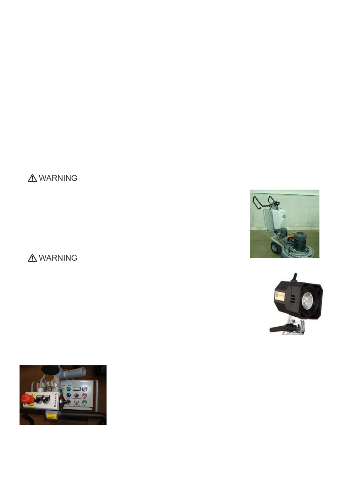
PROTECTIONDEVICES
Themachineisequippedwithseveralprotectiondevices
includingthefollowing:
Anemergencystopbutton
Aprotectionskirtandahoodforprotectingthetool
plates.
Thesedevicesprotecttheoperatorand/orotherpersonsfrom
potentialinjuries.Donotremovethem.Oncontrary,before
usingthemachine,pleaseensurethatallprotectivedevicesare
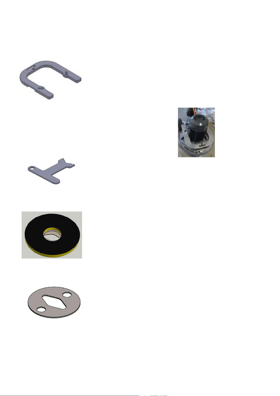
mountedandfunctionproperly.Thesecurityplatepreventsthe
QuickChangepadsfromlooseningduringwork.
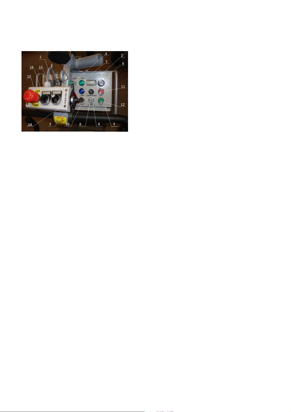
ARRESTFUNCTIONS
Functionsofarrestingofthemachinearefollowing:
Buttontostopthemotor(category1)
Emergencybutton(category1)
SAFEUSE
TheLavina®25LM‐S‐Eisdesignedtoeliminateallriskscorrelated
withitsuse.However,itisnotpossibletoeliminatetherisksof
eventualaccidentwiththemachine.Unskilledoruninstructed
operatormaycausecorrelatedresidualrisks.
Suchrisksare:
PositionRisksduetooperator’sincorrectworkingposition
TanglingupRisksduetowearinginappropriateworkingclothes
TrainingRisksduetolackofoperationaltraining
NOTE:Inordertoreduceallconsequencesoftheabove‐
mentionedrisks,weadvisethatmachineoperator’sfollowthe
instructionsinthemanualatalltimes.
RESIDUALRISKS
Duringthenormaloperatingandmaintenancecycles,the
operatorisexposedtofewresidualrisks,whichcannotbe
eliminatedduetothenatureoftheoperations.
BEFOREYOUBEGIN
Workingareamustbeclearfromanydebrisorobjects.
Afirst‐timeoperatormustalwaysreadthemanualandpay
attentiontoallsafetyinstructions.
Allelectricconnectionsandcablesmustbeinspectedfor
potentialdamages.
Groundwiresystemofthepowersupplymustalsobeinspected.
Performgeneraldailyinspectionsofthemachineandinspectthe
machinebeforeeachuse.
Alwaysinspectthesafetydevices:Mountthesecurityplateand
theQuickChangepads
Theemergencybreakmustbeclearandworking.
Thetoolprotectormustbeworking
Themachinemustbeclean
Neveroperatethemachineintherain!
Confirmthattherearenomissingpartsespeciallyafter
transportation,repair,ormaintenance.
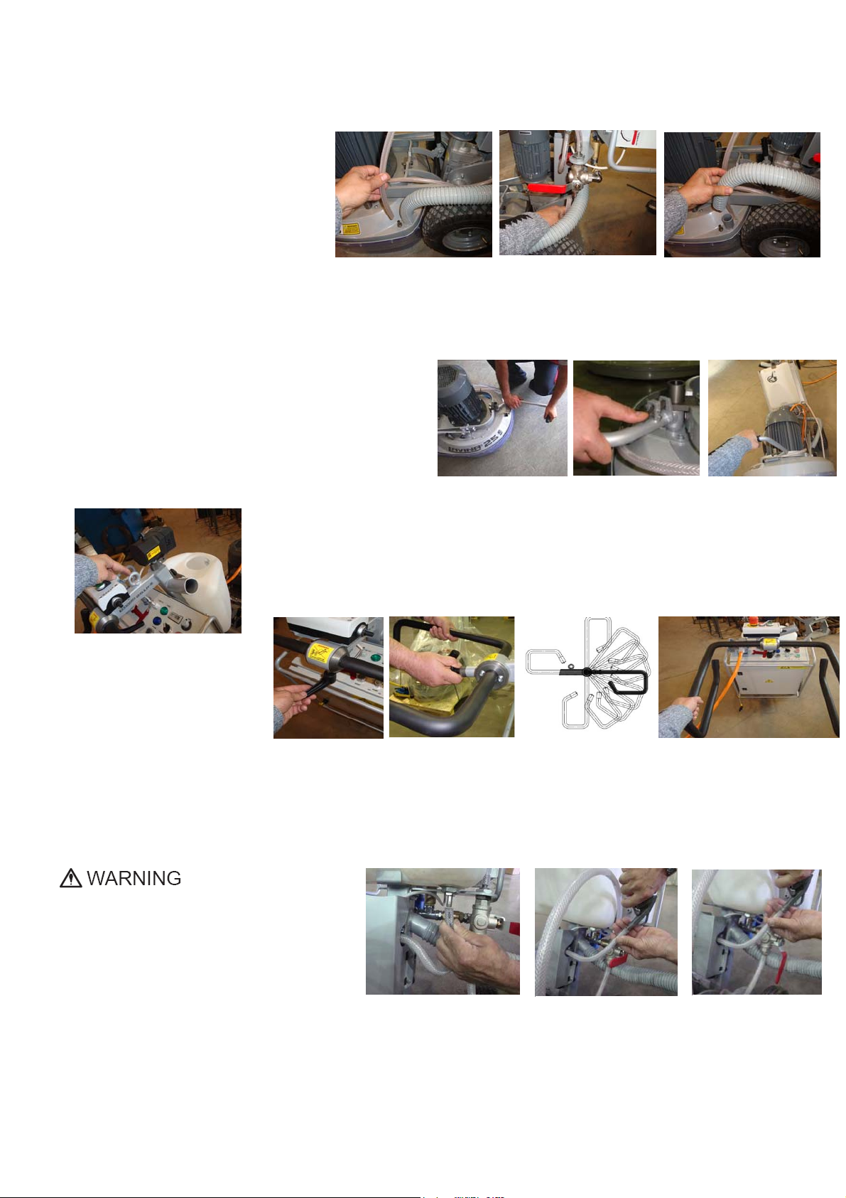
Beforefillingthewatertankwithwatermakesurethatthe
machineisnotworkingandthemainswitchisturnedoff.
Beforeturningonthemachinemakesurethatthebaseis
Placedonthefloor,themachineMUSTNOTbeinanupright
positionwhenturnedon!
OPERATINGMACHINE
WhenoperatingtheLavina®25LM‐S‐E,makecertainthatthere
isno
one,butyouaroundthemachine.
Neverleavethemachineunattendedwhileworking.
Theelectricalcablemustmovefreelyandmustbedamage‐
free.
Thewaterhosemustmovefreelyandmustbedamage‐free.
Checkifthefloor,youwillworkon,isnottoouneven.Ifthisis
the
case,itmaycausedamagetothemachine.
AfterWorkiscompleted
Cleanthemachineanditssurroundingsproperly
Emptyandcleanthewatertank
Unplugthemachineandwinduptheelectricalcable
Storethemachineinasafeplace
THEWORKAREA
Makecertainthatpeopleorvehiclesdonotenterthework
area.
Avoidcablesandhosesbeingintheway.
Alwayscheckthefloorfordebris.
PERSONALPROTECTIVE
EQUIPMENT(PPE)
Alwayswearsafetyshoeswhenworkingwiththemachine.
Alwayswearprotectorswhenworkingwiththemachine.
Allpersonnelintheimmediateworkareamustwearsafety
glasseswithsideshields.
Alwayswearsafetygloveswhenchangingthetools.
Alwayswearclothessuitablefortheworkenvironment.
OPERATOR
TheLavina®25LM‐S‐Emachine.
Theoperatormustknowthemachine’sworkenvironment.
Onlyoneoperatoratatimecanworkwiththemachine.The
operatormustbeproperlytrainedandwellinstructedprior
tooperatingthemachine.
Theoperatormustunderstandalltheinstructionsinthis
manual.
Theoperatormustunderstandandinterpretallthedrawingsand
designsinthemanual.
Theoperatormustknowallsanitationandsafetyregulations
pertainingtotheoperationoftheLavina25LM‐S.
Theoperatormusthavefloorgrindingexperience.
Theoperatormustknowwhattodoincaseofanemergency.
Theoperatormusthaveanadequatetechnicalknowledgeand
preparation.

Superabrasive UserManual OriginalLanguageLavina®25LM‐S‐E 12/2014
6
3.HANDLINGANDTRANSPORTATION
PREPARINGTHEMACHINEFORTRANSPORTATION
Unplugthemotorcableplugfromthe
controlboxanddisconnectthewaterhose
fromthemainheadbypullingitout(Fig.3.1)
(Fig.3.2).Windtheelectricalcableonthe
carriage.Releasethepinsets,whichattach
theheadtothecarriage.Pulloutthehoses
(Fig.3.3),anddismounttheheadfromthe
carriage.
TheheadoftheLAVINA®25LM‐S‐Emachine
hasonebarandsupporthandlesintendedforeasymovingandtransportation.
LIFTTHEMACHINEFROMWORKINGTOTOOLMOUNTINGPOSITION
Pushthefronthandledownandswivelittothefront(Fig.3.4).Pullthehandleupandensuretheheadisstableintheupright
position,for
Mounting/dismountingthetool.Ensurethatthewatertankis
empty
beforeflippingthemachine.Pulltheheadtouprightposition
(Fig.3.5).ThemachinesmanufacturedafterJan.12014are
withchangedlockingofthefronthandleasshownonthe
fig.3.4.1.
LIFTING
Liftingthemachinebycraneispossiblewiththeeyeboltthatismountedonthecarriage(seeFi
g.3.6).Theeyeboltandmachineconstructionisratedonlyfortheweightofthemachine.Donot
liftanyotherloadsonthemachine.Alwaysusehoistingequipmentratedfor300kgor660lbs
.
ADJUSTINGTHEHANDLE
TheHandleontheframeis
adjustableinheightandallows
theoperatortoworkinacorrect
andsafeposture.Themachines
manufacturedafterJan.12014
arewithchangedlockingofthe
handleontheframe.Theunlockingisbypullingthehandle(fig.3.4.1)Thelockingisautomaticallyunderactionofthe
spring.Fig.3.7.2showsallpossiblepositionofthehandle.Choosetheuprightpositiontomoveeasythemachine.
STORAGE
AlwaysstoreandtransporttheLavina®25LM‐S‐Emachineinadryplace.NevertransporttheLavina®25LM‐S‐Emachineunprotected;
itmaybedamagediftransportedunprotectedduringrainorsnow.
Whenstoringthemachine,thetemperaturemay
falltoorlessthan32F(or0°C),therefore,you
shouldemptythewaterfromthesystemusingthe
followingsteps:
‐ Pulloutthehoseofthetank(Fig.3.10)
‐ Usingcompressedair,blowoutthe
waterfromthesystemforthetwo
positionsoftheturn‐cock(Fig.3.11,Fig.
3.12).
Figure 3.1 Figure 3.2 Figure 3.3
Figure 3.6
Figure 3.10 Figure 3.11 Figure 3.12
Figure 3.5
Figure 3.4 Figure 3.4.1
Fi
g
ure 3.7 Figure 3.7.1 Figure 3.7.2 Figure 3.8

Superabrasive UserManual OriginalLanguageLavina®25LM‐S‐E 12/2014
7
4.OPERATION
PRELIMINARYCONTROLS
Inspecttheworkingareaasexplainedinthesafetyinstructions.Forwetuse,fillinthewatertankwhentheelectricalcableis
disconnected.Connectthevacuumextractorandensurethatthevacuumhoseisclearanditwillfollowthemachineeasily.Plugin
themachineandmakesurethatthepowercordisfreetofollowtheworkingdirectionoftheLavina®25LM‐S‐Emachine.
WATERFLOWCONTROLUNIT
Theoperatorcanchoosethewatersprayerinthefrontwhenthetapisinthehorizontalposition(Fig.4.1),thewaterwill
sprayunderthecoverofthemachinewhen
thelevelisintheverticalposition
(Fig.4.2).Theflowregulatingvalvelocatedon
thetank(Fig.4.2.1)isincreasingorreducing
thewaterflowtothe
working
area–infront
ofthemachineorunderthemainheadcover
ofthe
machine
/onlyformachinesproduced
afterJan.12014/
.
ADJUSTINGANDMOUNTINGTOOLS
Mountthetoolsonlyafterensuringthatthereisenoughdiamondbondmaterialleft.Besurethattheplatesarealwaysclean
beforemounting.WARNING:Alwayssecurethe“QuickChange”padswiththesecurityplate(Fig.4.3),lockwiththetoolholderkey
(Fig.5.3).DiamondtoolswithVelcroareattachedonthree9inchfoamplates(Fig4.4).Thefoamplatesaremountedonthekeylock
(butterfly).Alwaysusethetoolholderkey(Fig.5.3).
FRAMEBLOCKING(U‐JOINT]
Therelationbetweentheworkingheadandtrolleyistheframe(U‐joint),whichallowsrotationabout
twoperpendicularaxestobetterfollowtheprofileofthefloor.
Themovementalongtheoneaxiscanbefixedwithtwoscrews(Fig.4.5)andthatblockthelateral
movementofthemachine.
Figure 4.4
Figure 4.3
Figure 4.5
Figure 4.2.1
Figure 4.1 Figure 4.2

Superabrasive UserManual OriginalLanguageLavina®25LM‐S‐E 12/2014
8
THECONTROLBOARD
1. Powercableplug
2. DigitalRPMindicatorIndicatestherevolutionperminuteofthegrinding
plates(nottherevolutionperminuteoftheentireunit).
3. Electricalbox
4. Lampcablegland
5. InverteralarmledLightbluewhentheinvertergoesintoalarmmode.
6. WaterpumpswitchLightsorangewhenthewaterpumpisworking.
7. Powerledlightsgreenwhenthepowerison
8. Forward/Reverseswitchchooseforwardforclockwiserotationofthe
grindingplatesorreverseforcounterclockwiserotationofthegrinding
plates
9. PotentiometerchangestheRPMofthegrindingplatesfrom300‐1100
rpm
10. Resetbuttonresetsthealarmoftheinverter
11. OFFbuttonstopsthemotor
12. ONbuttonstartsthemotor
13. Emergencybuttonusedinemergencysituationsforstoppingthemotor
14.PotentiometerchangestheRPMoftheforwardmovementfrom0.1‐1km/h
15.Forward/Disengageswitch–fortheforwardmovementmotor
16.Start/Stopswitch–fortheforwardmovementmotor
STARTINGTHEMACHINE
First,followthedirectionsinthechapter:SafetyDevicesandSafetyInstructions.Next,pulltheemergencystop(13)toensurethat
themachineisinworkingcondition.Checkthepotentiometer(9)andPotentiometer(14)andensurethatitissetatthecorrect
workingspeed.Ifworkingwet,addwatertothefloor’ssurface.Ifworkingdry,omitthisstep,andinsteadswitchonthevacuum
unit.Finally,holdthemachinefirmlyandpushthestartbutton(12),turntheswitch(15)inforwardpositionandstartswitch(16)
instartposition.
OPERATINGTHEMACHINE
Guidethemachineinstraightlinesacrossthefloor,andwitheachnewlineoverlapalittlebitofthepreviouslycompletedsurface
line.Workataconstantspeedallowingthetoolstimetoworkataspeedappropriateforthetools’gritsize.Avoidvibrations.Donot
stoptheLavina®25LM‐S‐Emachineinonespotwhilethetoolsarestillworkingbecausetheywillleavemarksonthefloors’surface.
Whenworkingwet,firstchoosethewatertapposition(Fig4.2)forwaterfeedandperiodicallystartthepumptoreleasewateronto
thefloor’ssurface(Fig.4.6Pos.5).Whenworkingdry,checkthefloors’surfaceperiodicallytoensurethatdustisnotaccumulatingon
thesurface,alsocheckyourvacuumregularlytoensurethatitisworkingproperly.
Ifnecessarythemachinecanbemovedbackmanually,byputtingtheswitch(15)inthedisengageposition.
STOPPINGTHEMACHINE
Themachinemustbestoppedgraduallyuntilthemotorstops.Donotstopmovingthemachinebeforearrestingthemotor
becausethetoolscoulddamagethesurface.Tostop,turnthestopswitch(16)andpush(11).Usetheemergencybutton(13)only
inanemergency,oruseittoswitchthepowercompletelyoff.Remembernottoholdthemachineinonespotbeforeturningoff
themotor.
ALARM
Thealarmlight(5)willlightincasetheinvertergoesintoalarmmode.Themostcommonfailureismotoroverload.Toresetthe
mode,pushtheresetbutton(10).
Figure 4.6

Superabrasive UserManual OriginalLanguageLavina®25LM‐S‐E 12/2014
9
5.TOOLSANDACCESSORIES
WEIGHTS
Superabrasiveoffersadditionalweightsforincreasingtheproductivityofthemachine(Fig.5.1).
Eachadditionalweightweighsabout64lbsor29kg.Eachindividualapplication,typeand
conditionofsurface,powercapacityoftheoutlet,etc.willdeterminethenumberofweights
youcanusewithouttrippingabreaker.
Theadditionalweightsdependonthetools;itisnotalwayspossibletoaddweights.Some
toolsworktooaggressivelyandthemachinecanstop.Theweightcanbeordered
withitemnumberA08.00.00.00
TOOLHOLDERKEY
Thetoolholderkey(Fig.5.3)isusedforadjusting,mountinganddismountingofthefoam
plates.Alwaysusethekeyformounting.
ItemnumberisA03.00.00.00
FOAMPLATE
DiamondtoolswithVelcroaremountedonthefoamplate9“(Fig.5.4).Thefoamplateis
mountedonthe“QuickChange”System.
ItemnumberisLV‐9‐FP‐S
SECURITYPLATEFORQUICKCHANGEPADS
Plate(Fig.5.5)usedtoensurethe“Quickchange”pads.
ItemnumberisA38.00.01
Figure 5.5
Figure 5.3
Figure 5.4
Figure 5.1
Figure 5.2

Superabrasive UserManual OriginalLanguageLavina®25LM‐S‐E 12/2014
10
6.POPULARTOOLS
RECOMMENDEDTOOLS
QuickChangeSystemandToolingfeatureextremelyfastandconvenienttoolchanges,andalongtool
life,providingforgreatlong‐termcostsavings.TheQuickChangepadsareproducedinfourdifferent
bondsforsuperhard,hard,mediumandsoftconcrete,inavarietyofgritsizes.Theyareofferedwith
1or2buttonsorrectangularsegments,whichallowsyoutocustomizetheaggressivenessofthecut.
Calibragrindingdiscs:ourpopularceramicbonddiscsaredesignedfortheremovalofdifficultscratches
and
theysaveyouvaluabletimebyeliminatingtheneedformultiplepasseswithmetaltools.Theycanbe
usedwet
ordry,andarebestforhardconcreteapplications.
Theyare3‐inch,withincludedVelcrobackattachment.
NATO®polishingdiscsfeatureaspecialresinformuladesignedforbothwetanddryapplicationsandauniquedesignwith
widechannelsallowingforworkonacleanersurfaceandensuringaqualitypolish.Availablein3and4insizes.Theyarewith
includedVelcroattachment.
V‐HARR®PremiumPolishingPadsaredesignedformechanicallypolishingandrestoringconcrete;alsoidealforterrazzoand
hardstonefloors.V‐HARR®padsareofferedinawidevarietyofdiametersandgritsizestoaccommodatemanyapplications.
Dryuseisstronglyrecommended.
ShinePro®arehighqualitydiamond‐impregnatedpadsforfloormaintenance.Availableinavarietyofsizes,andaregreatfor
dailyuse.Whenusedwet,theyrequireonlywater(nowaxorchemicalsneeded)andareaveryenvironmentallyfriendlysolution
formaintainingfloors.
UseonlySuperabrasive’srecommendedtools.Formoretoolingoptions,visitwww.superabrasive.com

Superabrasive UserManual OriginalLanguageLavina®25LM‐S‐E 12/2014
11
7.EXPLODEDVIEW
LAVINA®25LM‐S‐EGENERALEXPLODEDVIEW(FIG.7.1)
LAVINA®25LM‐S‐ETOPCOVEREXPLODEDVIEW1(FIG.7.2)
LAVINA®25LM‐S‐EPLANETARYDRIVEEXPLODEDVIEW(FIG.7.3)
LAVINA®25LM‐S‐ETOPCOVEREXPLODEDVIEW2(FIG.7.4)
Figure 7.1 Figure 7.2
Figure 7.4
Figure 7.3

Superabrasive UserManual OriginalLanguageLavina®25LM‐S‐E 12/2014
12
LAVINA®25LM‐S‐EBOTTOMCOVEREXPLODEDVIEW1(FIG.7.5)
LAVINA®25LM‐S‐EBOTTOMCOVEREXPLODEDVIEW2(FIG.7.6)
LAVINA®25LM‐S‐EPULLEYUNITSEXPLODEDVIEW(FIG.7.7)
LAVINA®25LM‐S‐ECARRIAGEEXPLODEDVIEW(FIG.7.8)
LAVINA®25LM‐S‐ETOOLHOLDEREXPLODEDVIEW(FIG.7.9)
Figure 7.7
Figure 7.5 Figure 7.6
Figure 7.8 Figure 7.9

Superabrasive UserManual OriginalLanguageLavina®25LM‐S‐E 12/2014
13
8.MAINTENANCEANDINSPECTION
CLEANING
Keepyourmachineclean.Cleaningthemachineonaregularbasiswillhelpdetectandsolvepotentialproblemsbeforetheycan
causedamagetothemachine.Mostimportantly,checkandcleanthetoolplateconnections,powercordandplugs,vacuumhoses,
andwatertank.
CHECKDAILY
AfteroperatingtheLavinaSmachine,theoperatorshouldconductavisualinspectionofthe
machine.Anydefectshouldbesolvedimmediately.Payattentiontopowercords,plugsand
vacuumhoses,looseboltsorscrews.
Toolholders:Buffersandspidersareconsumablesandmustbevisuallycheckedeverydayand
replacedwhenneeded.Makesureflangesanddiscsaremountedandlockedwellinplace.The
keylockholders(butterflies)shouldbecheckedalso.
Checktherubberbuffersandthefixingoftheholdings.Theflangeholdingthebuffers(Fig8.11)
hastobefirmlyfixedtotheunit.Agapseentheremeansthatthereareloosescrewssecuring
theholder.Thescrewshavetobetightenedimmediatelytosafelyoperatethemachine.
Workingwithloosescrewsontheholdercouldalsocausedamagetothemachine.The
tighteningforceofthescrewshastobe25…30N.m(18…22ft/lbs).
Itisveryimportanttoregularlycheckthescrews(Fig.8.12)thatfixthe“QuickChange”holderto
thesafetypart,sothattheholderwillnotflyawayifthebuffersgetdamaged.Thetensionof
theplanetarybeltcanbecheckeddailybymovingtheheadandfeelingtheresistanceofthe
movingpulleys,ifthebeltslipstensionimmediately,seethechapter:Troubleshooting.
CHECKANDREPLACEAFTERTHEFIRST15WORKINGHOURS
Checkthebelttensionafter15hoursofworkingwiththemachine.
Thebottomcoverhasacontrolcover(Fig.8.2)thatallowsforfastandeasycontrol
andcorrectionofthebelt.Itisrecommendedthatthetensionofthebeltbetested
afterthefirst15hours,andtightenedifnecessary.Forthecorrecttension,seethe
chapter:TROUBLESHOOTING“mountingthebelt”.Everytimeyouopenthecontrol
cover,mountallthescrewsbackwithwashers.
CHECKEVERY200WORKINGHOURS
Every200workinghours,theoperatorshouldinspectallpartsofthemachinecarefully.
Mostimportantly,inspectandcleanthetoolplateconnections,powercordsandplugs,
vacuumhosesandthewatertankfilter.Also,checkthewaterflowofthepump.Checktheguardassembly.Makecertainthatthe
wheelsarecleanandarerotatingproperly.Inspectthecontrolbuttons.Iftherearedefectivecontrolparts,theyshouldbereplaced
immediately.Replacewornvacuumandwaterhoses.Checkthetensionofthebeltandtightenitwhennecessary.Forthecorrect
tensionseethechapter,TROUBLESHOOTING.
Dismountthetoolholders(seeTROUBLESHOOTING)replaceallparts(spider,buffers,sealercaps,“O”rings)withtheslightest
damage.
Opentheinspectioncoveronthemotorbasetocheckontheplanetarydrivingbelt;bymovingthemainhead,thebeltshouldnotslip
ontheplanetarypulleyanddrivethepulleys.
CHECKEVERY400WORKINGHOURS
Besidesthechecksof200workinghours,replacethesealerandV‐ringslikedescribedinthechapter:TROUBLESHOOTING,
replacingbeltandpulleyunits.Checkisthebeltsandbearingsareingoodcondition,changeifneeded.
VACUUM
Aspreviouslystated,frequentlycheckhosesandotherpartsforclogging.
WATERLEAKS
Replaceanyleakingpartsimmediatelyasthewatercoulddamageyourmachine.
MECHANICALPARTS
Partssuchasthebelts,sealrings,spidersandbuffers,andguardassemblyaresubjecttowearandshouldbereplacedasneeded.
ELECTRICALSYSTEM
Dustshouldnotenterthecontrolbox,asitwilldestroythecontacts.Remove(blowout)anydustpresent.
Figure 8.2
Fi
g
ure 8.1

Superabrasive UserManual OriginalLanguageLavina®25LM‐S‐E 12/2014
14
LAVINA®25LM‐S‐EELECTRICALSCHEMESWITHYASKAWAINVERTER
380Volt
LAVINA®25LM‐S‐EELECTRICALSCHEMESYASKAWA
CONNECTIONMAINCIRCUITTERMINALS
Figure 8.3
Figure 8.4
Themotorisconnectedin“Star”
380Volt,reminderforthe
wireconnectionofthemotor.
Figure 8.6
Figure 8.5

Superabrasive UserManual OriginalLanguageLavina®25LM‐S‐E 12/2014
15
Figure 9.2.7 Figure 9.2.8 Figure 9.2.9 Figure 9.2.10
9.TROUBLESHOOTING
INDEXOFPROBLEMSANDSOLUTIONS
9.1REPLACINGPOWERCORDANDPLUGS
Whenreplacingthepowercordorplugs,alwaysusecordsandplugswiththeexactspecificationsastheoriginalones.Neveruse
lowerqualityordifferenttypesofcordsorplugs.
Inaddition,takeintoconsiderationthedistanceoftheapplicationfromtheelectricalsource.Thegraterthedistance,thegreaterthe
resistanceandthelesscurrentthatwillbeavailableattheotherend,therewillbeavoltagedropandtheinverterwillgointoalarm
mode.Thisalsohappenedifseveralmachinesareworkingonthesamelineorwhenthegeneratorisunderrated.Ingeneral,our
standardcablecanbedoubledinlength,ifalongerlengthisneededyoucanreplaceallthecableswithcablesofabiggergagerated
forthelengthandtheamperage.
9.2DISMOUNTINGANDMOUNTINGTOOLHOLDERTOCHANGEBUFFERSANDSPIDER,CHANGINGV‐RINGSANDFELT‐RINGS
Tocheckorplacethebuffersandthespiders,thetoolholderhastobedismounted.Removethecountersunkscrewsontopofthe
buffer(Fig.9.2.1).Takethediscoff(Fig.9.2.2),thespidercanberemovedorreplaced(Fig.9.2.3).BylooseningthefourHexcapbolts
(Fig.9.2.4),thedisccomesloose(Fig.9.2.5)andthebufferscanbereplaced(Fig.9.2.6).Attention,whenmounting,alwaysusethe“blue”
threadlockingadhesive,exceptontheboltstolockthebuffers(Fig.9.2.5).Alwaysuseoriginalbolts.Dependingonthenumber(3,4,or
6)ofbuffers,theholdercanbemoreflexibleorrigid.
Whenthetoolholderisdismounted,youcanchangethesealers(V‐RingandFelt‐Ring).Takeout
felt‐ring,AdaptorandV‐Ring.Beforemountingcheckonwhichsidetheadaptorisfitting,
rememberthecorrectside.MounttheV‐RingwiththesmallestlipoftheVtoinside(Fig.9.2.7)
justpushtheV‐ringsothetopisonthesamelevelasthepulleytop(Fig.9.2.8).Thentakethe
adaptorinthecorrectwayandpushtheV‐Ringdownwiththeadaptor(Fig.9.2.9).Thelowestlip
oftheV‐Ringshouldonlybarelytouchitsglidingsurface;alsoneverpushtheV‐Ringdownwith
fingers.Mountnowthefelt‐ringontop(Fig.9.2.10).Closethesealerswiththecap(Fig.9.2.11).
Figure 9.2.1 Figure 9.2.2 Figure 9.2.3
Figure 9.2.4 Figure 9.2.5 Figure 9.2.6
Figure 9.2.11

Superabrasive UserManual OriginalLanguageLavina®25LM‐S‐E 12/2014
16
9.3TENSIONINGANDREPLACETHEPLANETARYBELT
Ifthebeltslipsorisbrokenseparatethe
carriagefrommainhead,pulloutmotor
plug(Fig.9.3.1),water‐(Fig.9.3.2)(Fig.9.3).
vacuumtubes(Fig.9.3.4).Takeoffthe
handles,fork,topframeandweight
holderssoyoucandismountthetop
cover(Fig.9.3.5).
9.4TENSIONINGUSEDPLANETARYBELT
Noticingalossofspeedinplanetarymovementcouldmeanthatthebeltforplanetarymovementneeds
replacing.Forreplacementinstructionssee9.5“MountingandTensioningaNewPlanetaryBelt.”
9.5MOUNTINGANDTENSIONINGANEWPLANETARYBELT
Figure 9.4.1 Figure 9.4.2
Figure 9.5.6
Figure 9.5.1
Figure 9.5.4
Figure 9.5.2 Figure 9.5.3
Figure 9.5.5
Figure 9.3.1 Figure 9.3.2 Figure 9.3.3
Figure 9.3.4 Figure 9.3.5

Superabrasive UserManual OriginalLanguageLavina®25LM‐S‐E 12/2014
17
Completelydismountthetensioningdevice(Fig.9.5.1).Make2marksonthedismountedbelt
thatareexactly10cmfromeachother(beltwithouttension)(Fig.9.5.2).Thepurposeisto
measure10.2cmonthebeltintensionfor2%tension,amaximumof2.5%isallowed(a
maximumof2.5%isallowed).ATTENTION:NEVER“OVER”TENSIONTHEBELT,THEBELTWILL
BEDAMAGEDANDITWILLNEVERRECOVERITSORIGINALTENSION
Mountthebeltbackaroundtheplanetarypulley;seethatthebeltisbehindthedrivingpulley
(Fig.9.5.3).Putthebeltaroundtheleftrollerofthetensioningdevice(Fig.9.5.4).Putthe
tensioningdevicebackinplaceandpullthebeltfromtherollerontherightside(Fig.9.5.5).Put
thebeltaroundthedrivingpulley(Fig.9.5.6).Begintotensionuntilthemeasureof10cm
betweenthemarksbecomes10.2cm(Fig.9.5.7)(Fig.9.5.8).Tightenthetensioningdevicewhile
turningtheboltmovetheplanetaryheadsothebeltcanslide.(Fig.9.5.8).Donotforgettolock
thetensioningdevice(Fig.9.5.9).
9.6CHECKINGTHETENSIONOFTHEBELT
Openthecovertoreach/checkthebeltandtensiondevice(Fig.9.6.1).
Whiletensioning,regularlycheckthetension.Pushthebeltdownwith
apressureof71N.Thisisapproximately7Kilogramsor15pounds,with
thispressurethebeltshouldmove3.5‐4mmor1/8”.Itis
recommendedthatthetensioningofthebeltbemeasuredwith
OptikrikIIdevice(measuringrange:500‐1400N)(Fig.9.6.2).Theoriginal
pressureP=1400Nandafterworkingawhile,P=1100N.
ATTENTION:NEVER“OVER”TENSIONTHEBELT,THEBELTWILLBE
DAMAGEDANDITWILLNEVERRECOVERITSORIGINALTENSION
Loosenthecontranuts(Fig.9.6.3),lightlyloosenthethreeboltsofthe
tensiondevice(Fig.9.6.4),andadjustthetensionwiththenutseenin
(Fig.9.6.5).
Whentherighttensionisreached:securethecontranutsandthethreeboltsforsupport.Reassembleinthesamemanner.
PLEASEMAKESUREYOUCHECKTHETENSIONOFTHEBELTAFTERTHEFIRST15HOURSOFOPERATION
Figure 9.5.7 Figure 9.5.8 Figure 9.5.9
Figure 9.5.10
Figure 9.6.3
Fi
g
ure 9.6.2
Figure 9.6.1
Figure 9.6.4
Figure 9.6.5

Superabrasive UserManual OriginalLanguageLavina®25LM‐S‐E 12/2014
18
9.7REPLACINGTHEPULLEYUNITS
Dismountguardandtopcoveraspreviousdescribed.
Dismountingthedrivingpulley:takethetopscrewouttoreleasethebushing(Fig.9.7.1),pushthebushingtogetherwiththe
washerup(Fig.9.7.2),pushwasherdownofthebushing(Fig.9.7.3).,takebushingout(Fig.9.7.4),pushkeyout(Fig.9.7.5),nowthe
washerreleases(Fig.9.7.6),dismountsealercap(Fig.9.7.7)(Fig.9.7.8),thepulleycanbereleasedwithtwocrowbarsbutdonotuse
excessiveforce(Fig.9.7.9),pushthesealercaptodismount(Fig.9.7.10),bymountingbacksecurewithsealant(Fig.9.7.11),center
theholestomountthepulley(Fig.9.7.12).
Figure 9.7.10
Figure 9.7.7 Figure 9.7.8 Figure 9.7.9
Figure 9.7.12
Figure 9.7.11
Figure 9.7.6
Figure 9.7.5
Figure 9.7.2
Figure 9.7.1
Figure 9.7.4
Figure 9.7.3
Figure 9.7.13 Figure 9.7.15
Figure 9.7.14

Superabrasive UserManual OriginalLanguageLavina®25LM‐S‐E 12/2014
19
Forthetwootherpulleys,loosenthefiveboltsofeachpulleybetweenthebaseplateandthemotorbasedisc(Fig.9.7.13).Anoil
sealring(Fig.9.7.14)andaseal(Fig.9.7.15)shouldbeplacedontopofthepulleybeforemounting.
9.8MOUNTINGTHEBELT
Seeheretheschematicofthebeltonthepulleys(Fig.9.8.1).
Todismount/mountthebelt,followthetensioninginstructionsinthechapter:
Checkingthetensionofthebelt.
9.9MOTORCONNECTION
Ifyoureplacethemotor,pleasecheckthecableconnectionandfollowthefiguresbelow.
LAVINA®25LM‐S‐E
Themotorisconnectedin“Star”
380Volt,reminderforthewireconnectionofthemotor.
Figure 9.9.1
Figure 9.8.1

Superabrasive UserManual OriginalLanguageLavina®25LM‐S‐E 12/2014
20
9.10FAULTDIAGNOSISINVERTERYASKAWAV1000
Pagesarereferringto
YaskawaElectricSIEPC71060618AYASKAWAACDrive–V1000TechnicalManual
Table of contents
Other lavina Floor Machine manuals
Popular Floor Machine manuals by other brands

Blastrac
Blastrac BMG-555PRO Original operating instructions

Minuteman
Minuteman Mirage 27" Parts and instruction manual

Craftsman
Craftsman 151.74946 Operator's manual

Trusted Clean
Trusted Clean TPL-SS20-TC Owner's manual & parts list

Husqvarna
Husqvarna BMG 780 Operator's manual

Eureka
Eureka KOBRA SH instruction manual