LAVISION Davis 8.2 User manual

LaVision
We count on Photons
Product-Manual
Camera Shutter
Item-Number(s): 1108327

Product-Manual for DaVis 8.2
LaVision GmbH, Anna-Vandenhoeck-Ring 19, D-37081 Göttingen
Produced by LaVision GmbH, Göttingen
Printed in Germany
Göttingen, September 23, 2013
Document name: 1003043_CameraShutter_D82.pdf

Contents
Contents
1 Safety Precautions 5
1.1 Laser Safety . . . . . . . . . . . . . . . . . . . . . . . . . . . . . 5
1.2 Seizures Warning . . . . . . . . . . . . . . . . . . . . . . . . . . 6
1.3 Camera / Image Intensifier Safety . . . . . . . . . . . . . . . . . 7
2 Camera Shutter 9
2.1 Introduction . . . . . . . . . . . . . . . . . . . . . . . . . . . . . 9
2.2 Shutter Driver . . . . . . . . . . . . . . . . . . . . . . . . . . . . 10
3 Wiring 13
4DaVis Hardware Setup 15
4.0.1 Camera shutter . . . . . . . . . . . . . . . . . . . . . . . . 15
4.0.2 Line Configuration . . . . . . . . . . . . . . . . . . . . . . 16
5 Device Settings 19
6 Troubleshooting 21
7 Customer Service 23
7.1 Order and Dongle Number . . . . . . . . . . . . . . . . . . . . . 23
7.2 Customer Settings . . . . . . . . . . . . . . . . . . . . . . . . . . 24
7.3 Log.txt . . . . . . . . . . . . . . . . . . . . . . . . . . . . . . . . 25
7.4 Export data set for support . . . . . . . . . . . . . . . . . . . . . 26
7.5 Camera Activity Logging . . . . . . . . . . . . . . . . . . . . . . 28
7.6 Shipment of defective items . . . . . . . . . . . . . . . . . . . . 29
3

Contents
4

1 Safety Precautions
Before working with your LaVision system we recommend to read the
following safety precautions. Observing these instructions helps to avoid
danger, to reduce repair costs and downtimes and to increase the reliability
and life of your LaVision system.
1.1 Laser Safety
If a laser1is integrated in your system it is important that every person
working with it has fully read and understood these safety precautions and
the laser manual of the specific laser.
Lasers included in LaVision systems may belong to CLASS 4 laser de-
vices, which are capable of emitting levels of both visible and invisible ra-
diation that can cause damage to the eyes and skin. It is absolutely neces-
sary that protective eyewear with a sufficiently high optical density is worn
at any time when operating the laser. The goggles must protect against all
wavelengths that can be emitted, including harmonics. See your Laser´s
manual for further details.
Class 4 laser beams are by definition a safety and fire hazard. The use of
controls, adjustments or performance of procedures other than those spec-
ified in the LaVision manual and laser manual may result in hazardous
radiation exposure.
AVOID EYE AND SKIN EXPOSURE TO DIRECT OR SCATTERED RADIATION.
FOLLOW THE INSTRUCTIONS YOU CAN FIND IN THE CORRESPONDING LASER
MANUAL FOR PROPER INSTALLATION AND SAFE OPERATION. USE PROTEC-
TIVE EYE WEAR ALL THE TIME WHEN OPERATING THE LASER.
Important instructions for safe laser handling:
• Before operating the laser contact your laser safety officer.
1In the following ‘laser’ means any kind of laser, in particular Nd:YAG- and dye laser as
well as Optical Parametric Oscillators at any wave-length and output-energy.
5

1 Safety Precautions
• Read and understand the instruction manual of the particular type of
laser. Take special care with respect to laser emission, high voltage
and hazardous gases if in use.
• Declare a controlled access area for laser operation. Limit access to
trained people. Never operate the laser in a room where laser light
can escape through windows or doors. If possible, cover beam paths
to avoid obstacles getting into the beam.
• Provide adequate and proper laser safety-goggles to all persons
present who may be exposed to laser light. The selection of the gog-
gles depends on the energy and the wavelength of the laser beam
as well as the operation conditions. Check the Laser´s manual for a
detailed description.
• While working with lasers do not wear reflective jewelry like watches
and rings, as these might cause accidental hazardous reflections.
• Avoid looking at the output beam, even diffuse reflections can be dan-
gerous.
• Operate the laser at the lowest beam intensity possible.
• Avoid blocking the output beam or reflections with any part of the
body. Use beam dumps to avoid reflections from the target.
• Wear clothes and gloves which cover arms and hands to avoid skin
damage when handling in the optical path. Especially UV-radiation
can cause skin cancer.
1.2 Seizures Warning
WARNING: HEALTH HAZARD! STROBE LIGHTING COULD TRIGGER SEIZURES
Some people (about 1 in 4000) may have seizures or blackouts triggered
by flashing lights or patterns. This may occur when viewing stroboscopic
lights or objects illuminated by such devices, even if a seizure has never
been previously experienced. Anyone who has had a seizure, loss of aware-
ness, or other symptoms linked to an epileptic condition should consult a
doctor before operating systems which include flashing lights, strobe lights,
or a pulsed or modulated laser.
Stop operating the system immediately and consult a doctor if you have
one of the following symptoms:
6

1.3 Camera / Image Intensifier Safety
• convulsions, eye or muscle twitching, loss of awareness, altered vi-
sion, involuntary movements, disorientation
To reduce the likelyhood of a seizure when operating a system:
• Do not look directly at flashing light sources or on illuminated objects,
e.g. into a strobe light or a flashing LED panel.
• Operate the system in a well-lit room.
• Take frequent breaks in normally illuminated areas.
1.3 Camera / Image Intensifier Safety
The camera integrated in your system is based on a CCD (Charge Coupled
Device) or CMOS (Complementary Metal-Oxide Semiconductor) sensor with
high resolution and high sensitivity. Optionally your system is equipped
with a built-in or external image intensifier.
A LASER BEAM FOCUSED ON THE CHIP OR INTENSIFIER, EITHER DIRECTLY
OR BY REFLECTION, CAN CAUSE PERMANENT DAMAGE TO THE CHIP OR IN-
TENSIFIER. ANY LASER POWERFUL ENOUGH TO PRODUCE LOCALIZED HEAT-
ING AT THE SURFACE OF THE CHIP OR INTENSIFIER WILL CAUSE DAMAGE
EVEN WHEN THE CAMERA OR INTENSIFIER POWER IS OFF. A CHIP OR IN-
TENSIFIER DAMAGED BY LASER LIGHT IS NOT COVERED BY ITS WARRANTY.
Important instructions for safe camera handling:
• Fully read and understand the instruction manual of the specific type
of camera.
• Put the protection cap on the camera lens whenever you do not take
images, especially when the laser beam is adjusted. Switching off the
camera / image intensifier does not protect the chip from damage by
laser light.
• Use full resolution of the sensor and always read out the complete
chip to have control of the intensity on all areas of the sensor.
• Make sure that no parts of the image are saturated, i.e. the intensity
is below maximum gray level (<4095 counts for a 12 bit camera,
<65535 counts for a 16 bit camera, ...).
7

1 Safety Precautions
• Start measurements with the lowest laser power and a small aperture
of the camera lens.
• Increase laser power step by step and check the intensity on the cor-
responding image. Make sure that the sensor does not run into satu-
ration.
• Bright parts in the experiment, like reflections on walls or big parti-
cles, will limit the maximum laser power. Modify the optical arrange-
ment of your setup in order to remove bright reflections from the
camera image.
8

2 Camera Shutter
2.1 Introduction
PIV cameras in frame straddling mode typically work with different inte-
gration times for the two frames (see camera manual for details). For this
reason a 532 nm interference filter that is used in front of the camera lens
is included in the PIV system to suppress the background light in the sec-
ond frame. So the effective exposure time is given by the length of the
laser pulse which is in the order of 10 ns. Since the wavelength of the
background light (e.g. of flames) is in the range of the used laser light it
can be necessary to use a mechanical camera shutter additionally. This can
reduce the exposure time of the second frame and the background noise
to ensure a higher validation rate for the evaluation.
time
camera
exposure
shutter
trigger
shutter
aperture
dt
open
duration
close
duration
T1A T1B
open duration + close duration
close duration
The shutter has been designed to give accurate, repeatable exposures for a
wide variety of applications. The standard shutter is available with 40 mm
aperture in cased configuration.
The benefit of the 40 mm aperture is that the camera shutter may be con-
nected in front of the camera lens and not in between the camera lens
and the CCD chip what allows for example to arrange the camera and lens
according to the Scheimpflug criterion in combination with the external
mechanical shutter. The camera shutter may be connected via external
(male) M52-filter thread to the camera lens while a bandpass filter may be
attached using the internal (female) M52-filter thread. The camera shutter
9
2 Camera Shutter
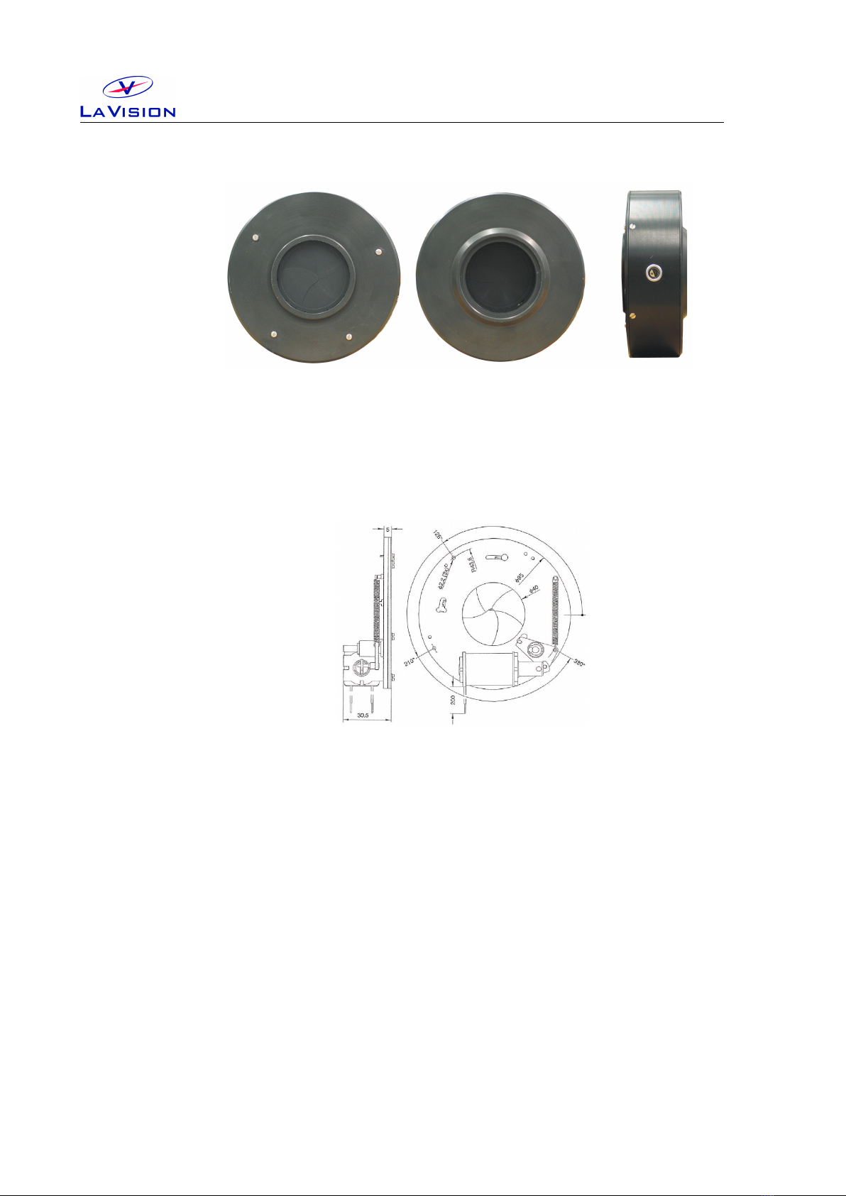
rear view
external (male) M52 thread
front view
internal (female) M52 thread
side view
Lemo connector
Figure 2.1: Camera shutter.
needs to be connected with the shutter driver with a connection cable. Use
the Lemo connector on the side of the shutter.
Figure 2.2: Camera shutter. All dimensions max. in [mm].
Aperture: 40 mm.
Exposure repetition rates: DC ≥15 Hz.
Dimensions: 95 mm ×30 mm (diameter×height)
Opening time: min. 10 ms, max. 20 ms
Closing time: min. 10 ms, max. 25 ms
2.2 Shutter Driver
For externally timed control the LaVision shutter driver is used. The
driver can be controlled from a BNC input. With key selection the driver can
be set in one of three modes, outlined below, depending on the application.
Exposure control can be activated by external pulse.
10

2.2 Shutter Driver
front view rear view
Figure 2.3: Shutter driver for two camera shutters.
Simple and straightforward controls allow the LaVision shutter driver to
be easy to use and configure. The LED indicator reveal shutter status at a
glance.
• Shutter operation exposure determined by external pulse source.
• Key switch on Normal position indicates normally closed shutter op-
eration, i.e. since a TTL HIGH level (=5 V) is provided to the Ext.Trig
port the shutter is closed, if a LOW level (=0 V) is provided to the
Ext.Trig port the shutter is open.
• Exposure determined by external pulse (BNC, TTL).
• Shutter interconnect cable included (Lemo).
• Operates on both 115 AC and 230 AC voltages.
• Size (HWD) 17 cm ×27 cm ×30 cm, weight 4.5 kg.
11

2 Camera Shutter
12

3 Wiring
PTU
Cam1
Network
VGA
Power Printer Port
COM1 COM2
Camera Cable
(Coax or FOL)
Blue BNC
Mouse
Keyboard
Computer Rear Panel
Camera
PTU Port A PTU Port B TTL I/O
Black BNC
Camera 1
Power
Data
Ext. Trig.
ShutterDriver
Camera
Shutter
Figure 3.1: Wiring of camera shutter and driver.
• Connect shutter with driver, plug the cable into the Shutter socket
at the driver front panel and the Lemo connector at the side of the
camera shutter.
• Connect Ext.Trig at the driver front panel with BNC labeled Cam
Shutter(Pin A7) of PTUPortA(Camera connector).
• Connect the driver to 115 V/220 V. Set key switch on rear panel to 1.
• Set the key switch on front panel to Normal.
13

3 Wiring
14

4DaVis Hardware Setup
The settings in the Hardware Setup dialog are entered by LaVision ap-
plication specialists during production or installation of your system. These
values should not be changed by the end user. Changing parameters may
cause a malfunction of the system.
4.0.1 Camera shutter
To be able to control the camera shutter on remote by DaVis it needs
to be added as device to the DaVis Hardware Setup dialog. Addition-
ally the camera shutter needs to be provided with trigger signals that are
synchronized to other devices, e.g. a trigger signal for the camera or a
light source for illumination. Therefore a camera shutter in a LaVision
system requires a Programmable Timing Unit (PTU) and a camera.
You can open the Hardware Setup dialog after start of the DaVis soft-
ware if you login as Expert User and click on the Setup icon.
If the camera shutter is already installed in the hardware setup you should
find a Camera Shutter card in the device list as a sub-device under the
Camera entry.
If this item is not present in the device list click on the Camera item to
highlight this and use the Add icon to select the Camera Shutter from
15

4DaVis Hardware Setup
the list of available hardware. Then click on the Camera Shutter entry in
the Recording tree and define the polarity of the required trigger signal.
This camera shutter (#1108326) needs a TTL trigger with negative polarity,
please make sure that the Inverted trigger option is selected.
4.0.2 Line Configuration
Using the Line Configuration card in the Recording tree of the Hard-
ware Setup dialog you can declare the Camera Adapter type you are
using to provide the camera shutter with the required trigger signals. There
are default adapters for certain systems, but in general there are different
adapters available that can be used. Therefore you need to make sure that
the correct adapter and trigger line is selected in your setup.
The trigger signal for the Camera Shutter is send on one line. By default
the camera adapter #1002047 Camera is used on Terminal: PTU Port
16

Aand the BNC cable with the Label: Cam Shutter is connected to the
Pulse input socket on the shutter driver.
17

4DaVis Hardware Setup
18

5 Device Settings
The timing for the camera shutter may be selected on the Camera Shutter
card you can open using the Device button in the Recording dialog.
Typical values for timing of the shutter are:
•Open duration: 6 ms.
•Close duration: 4 ms.
The value for Open duration is not critical and may be selected higher. But
the value for the Close duration needs to be adjusted carefully for each
device as the timing is based on mechanical components (spring and di-
aphragm) which does not allow to manufacture shutter with identical prop-
erties.
In order to adjust the value for the Open duration start with a value that
is sufficient long (e.g. 8 ms) and take images in double frame mode while
the PulseA of the laser is triggered and illuminates the 1st frame of the
camera. Reduce the value for the Open duration until the shutter will
block the laser pulse. Then increase the value by 100 µs.
In order to adjust the value for the Close duration start with a value that
is sufficient long (e.g. 6 ms) and take images in double frame mode while
the PulseB of the laser is triggered and illuminates the 2nd frame of the
camera. Reduce the value for the Close duration until the shutter will
block the laser pulse. Then increase the value by 100 µs.
19

5 Device Settings
20
This manual suits for next models
1
Table of contents
Popular Remote Control manuals by other brands

Woodbridge
Woodbridge LT610 user manual

Inel
Inel ORS-X2T General instructions for installation and use

Universal Remote Control
Universal Remote Control CLIKR-5 UR5U-8500 operating instructions

Hitachi
Hitachi RAR-5F1 manual

Supertech
Supertech TVR-004/B Service manual

Zenith
Zenith Flash-Matic operating guide


