LAWRENCE FACTOR HF-961-111 Guide
O f O p e r a t i o n , S e r v i c e a n d P a r t s
M A N U A L
Purification Appliance Model
HF-961-111
High Purity At High Pressure

The information contained herein is based upon our testing and experience. It is believed to
be accurate. Since operating conditions may vary and since we do not control such
conditions, Lawrence Factor, Inc. DISCLAIMS ANY WARRANTY, EXPRESSED OR
IMPLIED, with regard to the use of our products.
Due to the evolving nature of our products and our continued effort to improve those
products, the information contained in this publication may not be identical to the product.
Copyright © 2006, Lawrence Factor, Inc.
4740 NW 157 Street,
Miami Lakes, Florida 33014
305 430-0550
High Purity At High Pressure
COPYRIGHTS & TRADEMARKS
L-Factor Trademarks: Aero Lube, CO-Cop, Lab on Locale, L.F.W., L-Factor, Monoxycon, New Parts, Oxy Lube, Seco Lube, Vaporshell, and X-tractor are
TRADEMARKS of Lawrence Factor, Incorporated. X-pendable, X-zam, and Lawrence Factor are REGISTERED TRADEMARKS of Lawrence Factor, Inc.
Other Trademarks: A2LA is a registered trademark of American Association for Laboratory Accreditation. Aero Dri is a registered trademark of Kiko,
Incorporated. Air Dry Corporation of America is a registered trademark of Air Dry, Corporation. American Bristol is a registered trademark of American
Bristol, Industries. ANDI is a registered trademark of American Nitrox Divers, Incorporated. Bauer Compressors is a registered trademark of Bauer
Compressors, Incorporated & Bauer Kompressoren, GMBH. Bristol Pneumatics is a registered trademark of Bristol Pneumatics, Limited. C.G.A. is a
registered trademark of Compressed Gas Association, Incorporated. C.S.A. is a registered trademark of Canadian Standards Association. Coltri-Sub is a
registered trademark of Aerotecnica Coltri, Incorporated. Deltech and Del-Monox is a registered trademark of Deltech Engeneering, Incorporated. Eagle
Compressors is a registered trademark of Eagle Compressors, Incorporated. Fluid Concepts is a registered trademark of Fluid Concepts, Incorporated.
Hamworthy is a registered trademark of Hamworthy USA, Incorporated and Hamworthy Engeneering, Limited. Ingersoll-Rand is a registered trademark
of Ingersoll-Rand, Company. Innerspace Research is a registered trademark of Innerspace Research, Incorporated. Jordair is a registered trademark of
Jordair Compressors, Incorporated. Mako Compressors is a registered trademark of CompAir Mako, Incorporated. Max-Air is a registered trademark of
Max-Air Compressors, Incorporated. Midland Diving Equipment is a registered trademark of Midland Diving Equipment, Limited. N.A.V.S.E.A. is a
registered trademark of Naval Sea Systems Command. N.F.P.A. is a registered trademark of National Fire Protection Association. Nautica is a registered
trademark of Nautica, Incorporated. O.S.H.A. is a registered trademark of Occupational Safety and Health Administration. Poseidon Compressors is a
registered trademark of Poseidon Kompressoren GEMSBH & Bauer Compressors Inc. Pressure System is a registered trademark of Pressure System,
Incorporated. Robbins Aviation is a registered trademark of Robbins Aviation, Incorporated.
Aftermarket Use: X-pendable filter cartridges, New Parts compressor parts, and many other items depicted in the pages are intended and sold for
aftermarket use only. Part numbers, graphics, photos, trade names, and corresponding printed matter are not intended to imply that any items in
this Catalog or Website are original brand products. Although the quality of most of the items listed herein equals or exceeds the performance of
the original brand, none of these items are manufactured or associated with the original manufacturer. L-Factor in no way represents itself or it's
products to be related to the OEM or their brands.
Lawrence Factor, Incorporated - 4740 NW 157 Street, Miami Lakes, Florida 33014 - © All Rights Reserved

TABLE OF CONTENTS i
Table of contents
Table Of Contents. . . . . . . . . . . . . . . . . . . . . . . . i
Specifications . . . . . . . . . . . . . . . . . . . . . . . . . . 1
Safety Warnings . . . . . . . . . . . . . . . . . . . . . . . . 2
Introduction . . . . . . . . . . . . . . . . . . . . . . . . . . 3
Identification Of Components . . . . . . . . . . . . . . . . . . . 4
Installation . . . . . . . . . . . . . . . . . . . . . . . . . . . 5
Operation . . . . . . . . . . . . . . . . . . . . . . . . . . . 6
Cartridge Installation . . . . . . . . . . . . . . . . . . . . . . 7
Cartridge Installation . . . . . . . . . . . . . . . . . . . . . . 8
Maintenance . . . . . . . . . . . . . . . . . . . . . . . . . . 9
Supplements . . . . . . . . . . . . . . . . . . . . . . . . . . 10


Model Number
Design Gas (Gases)
*Maximum Process Gas
Maximum Operating Pressure
Minimum Operating Pressure
Repressure Cycle Life
Safety Factor
Maximum Operating Temperature
Minimum Operating Temperature
Maximum Ambient Temperature
Minimum Ambient Temperature
Power Supply
Ground Strap Requirement
Dimensions
Inlet Port Size
Discharge Port Size
Auxiliary Port Size
Non Adjustable Restricted Flow
HF-961-111
Compressed Air or Inert Gas
*18,000 Cubic Feet
5,000 PSI
2,000 PSI
15,000 Cycles for Cartridge Holders
4:1 (ASME)
0
100 F
0
-40 F
0
105 F
0
-40 F
Not Applicable
Required (Not Supplied)
11” W x 38” H x 5” D
1/4”
1/4” FNPT
1/4” FNPT
9 SCFM At 3200psi
“HF SERIES” PURIFICATION APPLIANCE 1
Specifications
* Dependant on actual operating conditions.

“HF SERIES” PURIFICATION APPLIANCE
2
Safety Warnings
Safety
Isolate appliance from gas stream and depressurize prior to any service action. Never direct compressed gases at
bodily openings, eyes, or skin. Empty volatile gases from appliance into "drain gas” accumulator. Use appropriate
monitoring devices when dealing with critical or life support gas. Never exceed maximum operating conditions set
forth herein and/or on appliance nameplate. DO NOT use this appliance with Oxygen or Oxygen rich gas mixtures.
DO NOT connect this appliance to any system common with compressed oxygen. Disconnect all power supplies prior
to any service action. Some components used on this appliance may have a limited cycle lifespan and must be
replaced after that span has lapsed. Carefully read supplement section.
WARNING: When performing installation, adjustments, or any kind of service work: ensure that ALL pressure has first
been released and that ONLY trained personnel are carrying out tasks. NEVER remove retaining or adjusting screws
while device is under pressure. Safety valve should be returned to factory for service.
*Use only genuine Lawrence Factor replacement parts in order to guard the validity of your warranty and reliability of this appliance.

“HF SERIES” PURIFICATION APPLIANCE 3
Introduction
Introduction
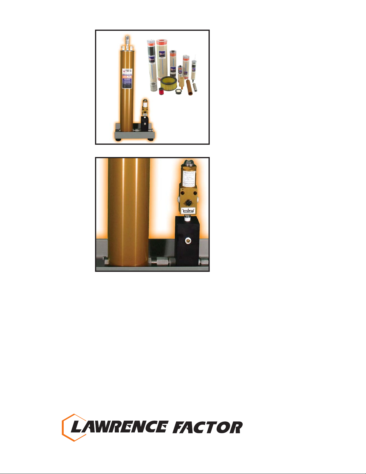
This L-Factor appliance is a “special application” compressed gas purifying system designed to operate at high
pressures. It is intended to treat once purified gas a second time (second stage purification) in order to achieve
ultrahigh levels of purity. This is a “once through” type appliance utilizing Disposable Cartridges. The appliance, or
hardware, operates in concert with the cartridges, or software, which are the core of the system.
With the compressed gas entering the device, it is preconditioned by an optional Mechanical Filter and then flows
evenly through a series of Cartridge Holders. These towers contain the Disposable Cartridges which can be
configured according to customer needs and applications. It is of paramount iportance that the user not vary from the
cartridge models specified on the appliance. Always change all cartridges at the same time, as a set.
On some models, a cartridge change indicating device (Eyeball Indicator) is fixed at the inlet to the tower chain in order
to tap off a sample of the gas for constant evaluation. The standard device will indicate RH of the gas by coloremetric
change as viewed through a window placed at the topside of the “Eyeball”. Replacement elements are available for a
range of RH as well as other kinds and levels of substances.
In the case of compressed air, a minimum level of grade “E” (according to the CGA) is expected to enter the appliance.
The gas now follows a path through a final Micronic Filter towards discharge at the Priority Valve and into the outlet
piping.
The standard Appliance is supported on an angle plate chassis that facilitates fixing to a permanent vertical
foundation or hanging from another equipment. There is a Pressure Gauge at the discharge manifold in addition to a
system Drainage Valve. Some models are supported by an optional freestanding chassis which also supports
electronic monitoring units.
Special attention has been paid to all materials and treatments in order to guard the ability of this equipment to achieve
the high gas purities required of it. Carefully follow the instructions set forth in this manual and use added precautions
to avoid internal contamination.
It is of paramount importance that the user does not exceed the operating limitations set forth for this appliance. Do
Not exceed pressure, flow rate, or temperature ratings.
Identification of Components
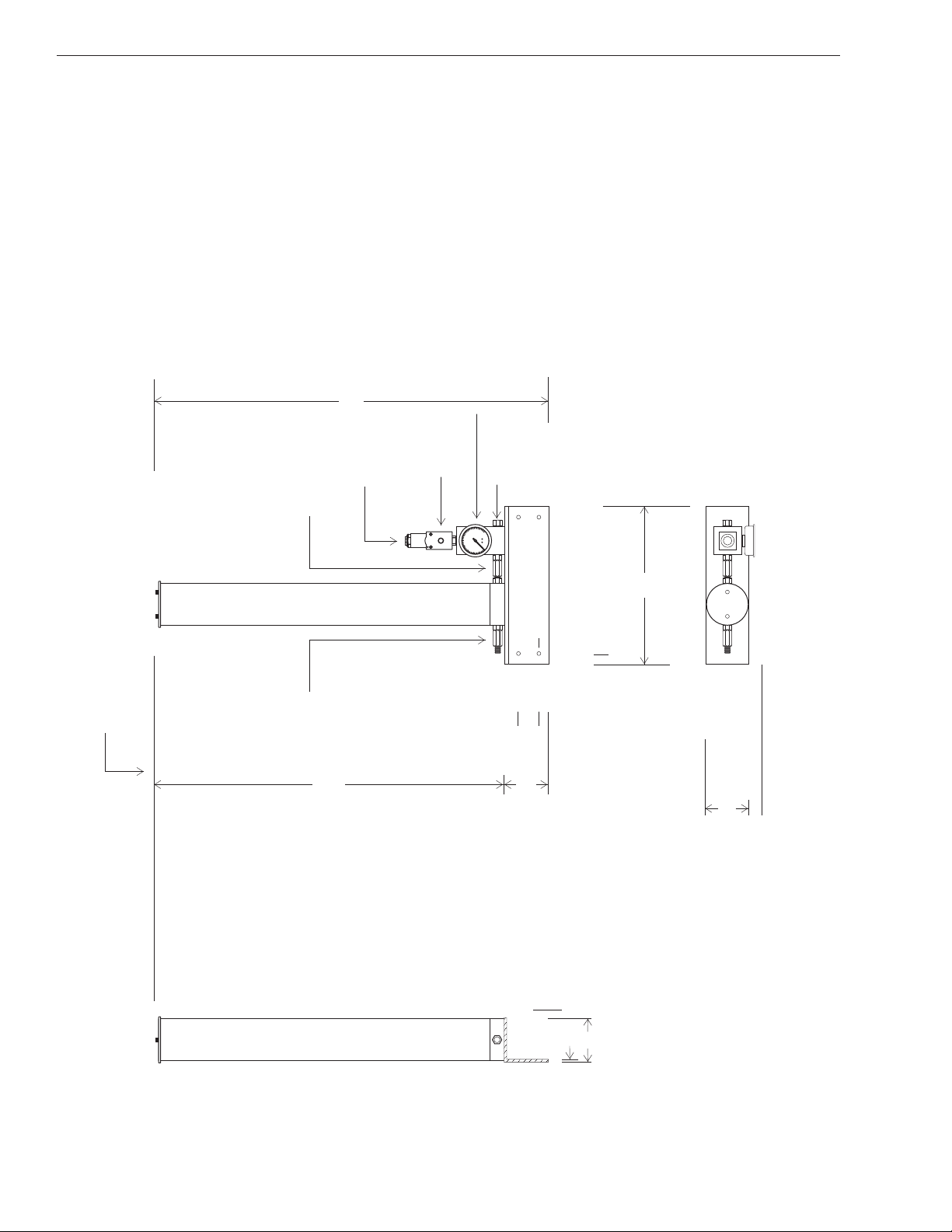
Refer to this illustration in order to identify components as they are discussed throughout the remainder of this
manual. Be aware that some items may not appear in the exact form as they exist on the actual appliance.
“HF SERIES” PURIFICATION APPLIANCE
4
Identification
½” Holes
Allow 28” Overhead Clearance For Cartridge Change
34”
Check Valve Check Valve
Priority Valve
4” 2”
1”
1”
Side View
4”
1/4”
11”
4”
1”
1”
Outlet
(1/4” NPT)
Vent
Micronic Filter (Internal)
Top View
38”

“HF SERIES” PURIFICATION APPLIANCE 5
Instalation
Installation
It is assumed that the person installing this equipment is experienced in this field and fully acquainted with the
standard engineering practices.
Carefully unpack unit while ensuring to protect any sensitive devises such as pressure gauges and instruments.
DO NOT open any valves until unit is fully installed. This appliance has been carefully cleaned and protected against
contamination by atmospheric substances.
Refer to "IDENTIFICATION" page of this manual for location of components.
Appliance should be permanently affixed to a solid foundation by means of the anchoring holes located at the back of
the angle plate or (in the case of freestanding models) on the feet of the main chassis. Consider all piping joints when
orienting unit. DO NOT expose to excessive vibration.
Make up piping connections using joint compound which is compatible with the compressed gas application. If using
Teflon tape, do not allow to overlap edges of fittings since pieces may break loose under operation and cause
blockages.
Ÿ INLET CONNECTION should be made with a flexible hose.
Ÿ DISCHARGE CONNECTION should be made with a flexible hose. Note that the discharge is located at the
“back pressure valve" and there are two (2) ports for your use, one may be plugged if not required.
ŸRELIEF VALVE (if supplied) vents to atmosphere. An optional valve is available with NPT vent connection to
facilitate controlled discharge. Never tamper with relief valve settings.
ŸSYSTEM VENT discharges to atmosphere. An optional valve is available with NPT connection to facilitate
controlled discharge.
ŸA GROUNDING STRAP (not provided) must be attached to appliance.
ŸADEQUATE CLEARANCES must be allowed for servicing and cartridge changes.
ŸPROVIDE MEANS OF ISOLATION of this appliance from gas stream during service and cartridge changes.
ŸCONTAMINANT DETECTION (Optional) and alarm should be installed at discharge of appliance when in life
support air/gas service.
ŸOVER TEMPERATURE PROBE (Optional) and alarm with system shutdown devise should be installed at
discharge of compressor system as well as at the discharge of this appliance.
DO NOT install in location where ambient temperatures could exceed 110F degrees. DO NOT expose to electrical
charges or sparks. DO NOT install in system where gas flow rates could exceed the rating of this appliance. The
cartridge set must be installed prior to placing appliance into service. See section on “Installing Cartridges”.

“HF SERIES” PURIFICATION APPLIANCE
6
Start Up / Operation
Start Up
The following procedure must be followed on initial start-up (AFTER CARTRIDGES HAVE BEEN INSTALLED) and
on each occasion where the appliance has been shutdown, serviced, or had a cartridge change.
NOTE that some appliances will come supplied with storage elements installed and slightly pressurized.
ŸVENT pressure from appliance using "System Vent". Be careful to drain the appliance slowly.
ŸREMOVE CARTRIDGE elements from holders according to "Cartridge Change" instructions and install new
cartridge elements. (This is done ONLY on initial start-up and on occasions where elements are due for change)
ŸCLOSE "System Vent Valve".
ŸPRESSURIZE appliance (SLOWLY) by opening the "Inlet Isolation Valve" (Optional). Bring up to full operating
pressure in 500 PSI steps while verifying there are no leaks in system.
ŸFLUSH contaminants from main appliance and piping by opening the "Outlet Isolation Valve" (Optional) and
permitting a small flow of air to discharge downstream or to atmosphere.
ŸTHE APPLIANCE MAY NOW BE PLACED ON LINE by fully opening the "Isolation Valves".
Operation
PRECAUTIONS: Always employ safe practices in handling of volatile or respiratory gases. Wear protective gear
when installing, operating, or servicing compressed gas apparatus. Never smoke, cause sparks or fire, or switch
electrical equipment while in the presence of volatile gases. MSDS are available for materials contained in disposable
cartridges. Use approved methods of disposal for cartridges. Never exceed ratings of this appliance.
INSTALLATION: Appliance must be properly installed prior to operation. See section titled "Installation".
CARTRIDGE INSTALLATION AND CHANGES: Cartridges must be properly installed prior to operation. See section
titled "Cartridge Installation".
SERVICE AND MAINTENANCE: See section titled "Maintenance Schedule" and instructions for each individual
component at the "Supplements" section of this manual.
Once the appliance is running it will manage itself. The operator need only perform proper maintenance, drain
condensate from mechanical filter when needed, and cartridge changes when due. The "Eyeball Indicator" will assist
the operator in determining cartridge change. See "Supplements" section of this manual.
DRAINING CONDENSATE FLUID must be done on a periodic basis. Since each system is operating under various
conditions the intervals between drainings should be established after operating experience.

“HF SERIES” PURIFICATION APPLIANCE 7
Service Of Cartridges
Installation of Cartridges
PRECAUTIONS: Always depressurize and remove electrical source from this appliance prior to performing any
service. Do Not direct compressed gases at bodily openings, eyes, or skin. Do Not attempt to regenerate disposable
cartridges. Do Not rotate cartridges - always replace all cartridges as a set, otherwise contaminants could be
reintroduced to gas stream.
CARTRIDGE SERVICE INTERVALS: This appliance can only process the amount of gas rated on the nameplate of
the appliance as well as on the front page of this manual. Cartridges must be changed at their maximum calculated life
or every six months, whichever comes first. Many variables will contribute to the capability of this equipment. It is our
recommendation that a reliable monitor be placed at the discharge point in order to gauge the humidity level of the gas
in determining the appropriate change of cartridges. Otherwise, approximated cartridge change can be calculated
with the following formula.
This formula is based on average operating conditions for appliance. Low pressures or high temperatures will reduce useful cartridge life.
Gas Process Rating of Appliance in SCF
SCFH Gas Flow =Life expectancy of cartridge set
in operating hours
TOOLS REQUIRED: Spanner wrench (available from
manufacturer) or 5/8" closed end wrench, non-hydrocarbon
grease with applicator, graphite paste, leak detector pliers
and a flashlight.
PROCEDURE: Refer to "IDENTIFICATION" page of this
manual for location of components. Turn system "OFF" and
isolate appliance from gas stream by means of isolation
valves (optional). Vent compressed air from system by means
of system pressure release valve. Monitor gauges to be
certain that appliance is empty.
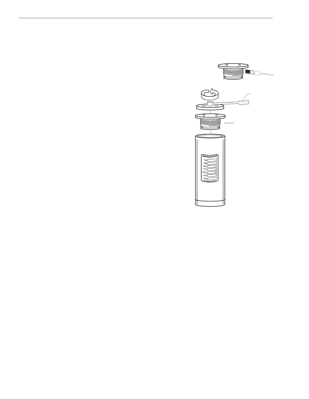
Remove cylinder head(s) from cartridge holder(s) as
illustrated. You should be able to turn the cylinder head with
moderate pressure. If force is required, STOP and recheck
appliance pressure to verify that it is empty.
Lift spent cartridge from cylinder using the lifting bail provided
at top of cartridge.
Using flashlight CAREFULLY inspect interior of cylinder for
extraneous matter and any wear exhibited on the cylinder
walls. Any deterioration may be cause for replacement.
Remove cartridges from packaging, one at a time, holding
them with the outer wrapper used as a "glove" in order to
prevent contamination by handling. Remove lower protective
seal from mating end of cartridge. Suspending cartridge by
lifting bail, lower new cartridge into place. NEVER drop
cartridge into cylinder. Apply slight pressure to seat cartridge
onto mating stem/port of cylinder.
SPENT
NEW
Installation of Cartidges
PROCEDURE (continued) Using applicator, lubricate cylinder head O-
Ring(s) with non-hydrocarbon grease. Also, apply a light film of graphite
paste to the threads using care not to contaminate interior of cylinder
(non-hydrocarbon grease may be used in place of the graphite paste).
Note that the cylinder foot should be serviced periodically in this same
manner. Refer to the maintenance schedule for recommendations
Reassemble in reverse order using the spanner wrench. If binding is
encountered STOP and check for obstructions, cartridge position, and
thread clearance. DO NOT over tighten cylinder ends. Tighten until dust
cover or lip touches cylinder and then back out slightly.
Open the inlet isolation valve to permit gas flow into appliance.
Repressurize in 500psi steps while checking for leakage until working
pressure is reached. Verify appliance pressure by means of the gauges.
Note that the back pressure valve will limit gas flow from leaving
appliance until pressure range of 1800-2200psi is reached.
Purge contaminated air from system by means of the system pressure
release valve.
Open discharge isolation valve to place appliance back on line.
“HF SERIES” PURIFICATION APPLIANCE
8
Service Of Cartridges
SPANNER
WRENCH
HEAD
“HF SERIES” PURIFICATION APPLIANCE 9
Maintenance
Note: Always employ safe practices in handling volatile or respiratory gases. Wear protective gear when installing, operating, or
servicing compressed gas apparatus. Never smoke, cause sparks or fire, or switch electrical equipment while in the presence of
volatile gases. MSDS are available for materials contained in disposable cartridges. Use approved methods for disposal of
cartridges. Never exceed ratings for this appliance. Always depressurize this appliance prior to any service activity. Do not direct
compressed gases at bodily openings, eyes, or skin. Do not attempt to regenerate disposable cartridges.
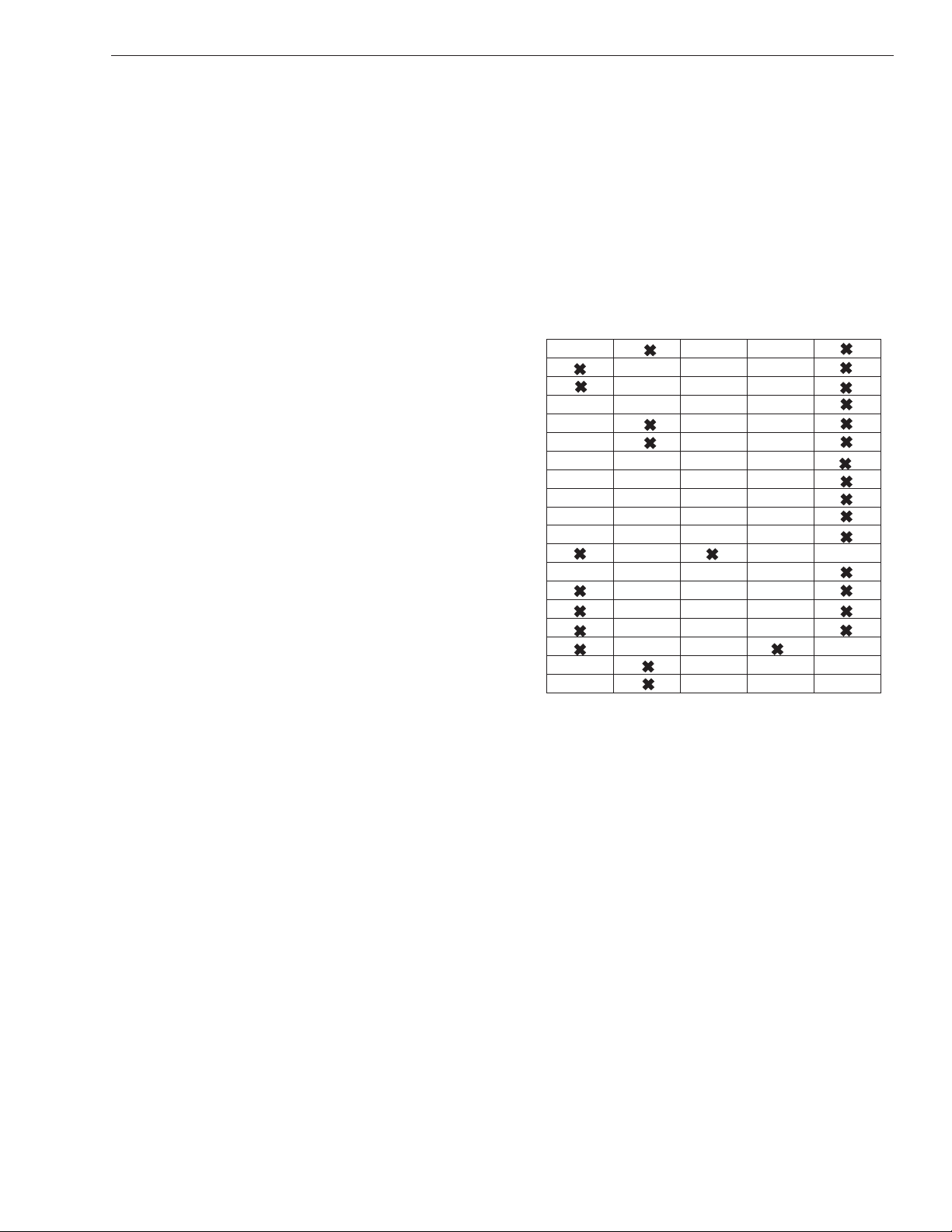
Replace FILTER CARTRIDGES
Lubricate O-RING SEALS in "Cartridge Holders"
Apply grease to CYLINDER HEADS AND FEET of "Cartridge Holders"
Replace O-RING SEALS in "Cartridge Holders"
Replace MICRONIC FILTER element and seal
Lubricate O-RING SEALS and THREADS in "Mechanical Filter"
Replace O-RING SEALS in "Mechanical Filter"
Replace O-RING SEALS in "Eyeball" Indicator
Replace SEALS in "Drain Valve" and "Vent"
Replace all SEALS in "Priority Valve"
Replace all SEALS in "Check Valves"
TEST "Relief Valve" operation
Replace all SEALS in "Isolation Valve"
Inspect all PIPING JOINTS for leakage
Inspect all SEAL JOINTS and COMPONENTS throughout appliance for leaks
Inspect CYLINDER wall conditions
Inspect FLUID LEVEL in "Gauges" and replace gauge if less than 2/3 full
Replace MECHANICAL FILTER unit at limits of repressurization cycle life
Replace CARTRIDGE HOLDERS at limit of repressurization cycle life
*Please refer to SUPPLEMENTS SECTION for details and procedures.
MAINTENANCE SCHEDULE
Anytime
service is
performed
Upon
Demand Monthly Every
3 Months
Every
6 Months

“HF SERIES” PURIFICATION APPLIANCE
10
Supplements
Supplement Inserts
These supplement pages are provided for additional detail on each component. Refer to them for replacement parts
and service information.
Lawrence Factor, Inc. is not responsible for the accuracy or reliability of these inserts.
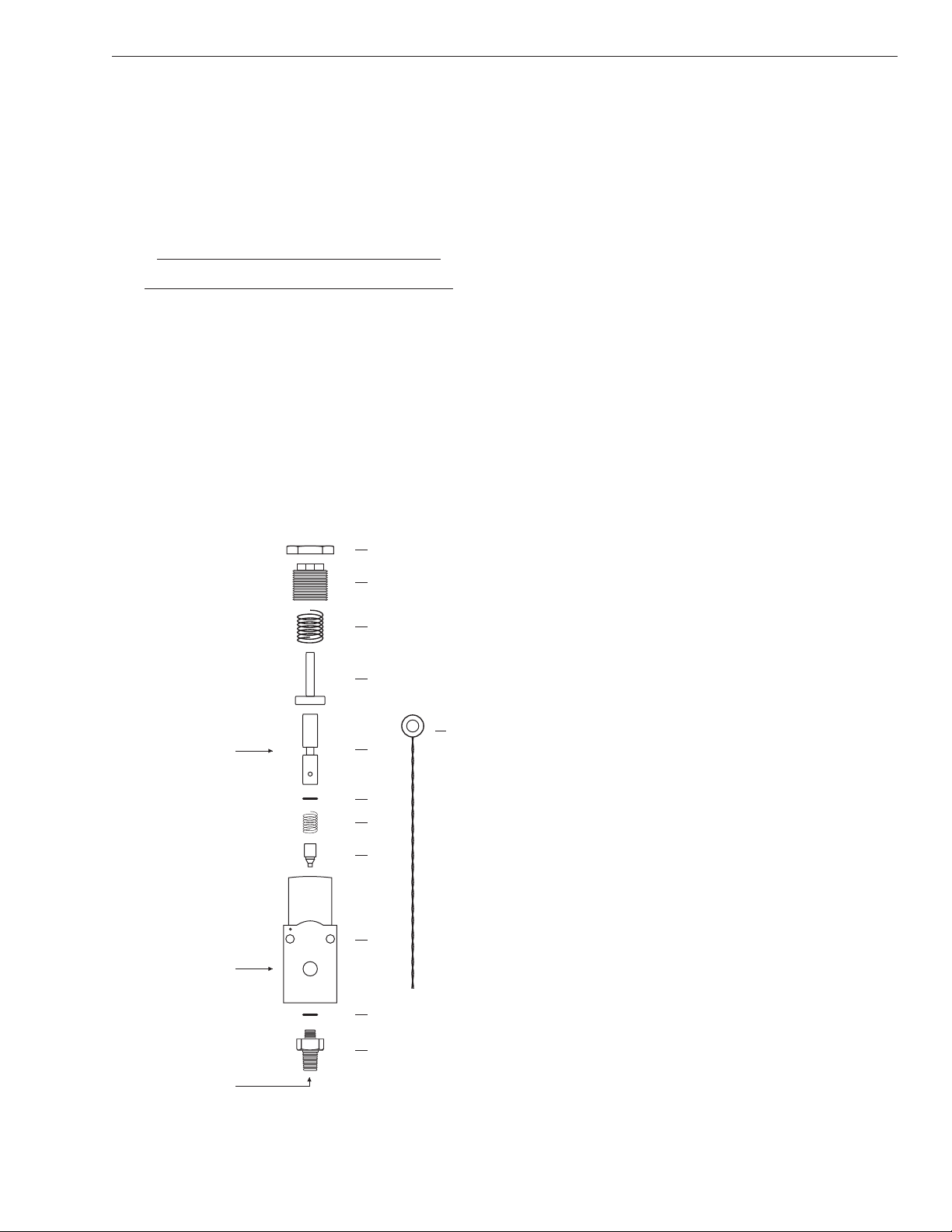
ASSEMBLY AND DISASSEMBLY GENERAL
Assembly and disassembly can be done by following the
drawings and parts list. Also refer to the repair section on the
opposite side of this sheet for disassembly sequence.
PARTS LIST - SERVICE KIT #RK-530210-HS
ITEM QTY DESCRIPTION
1 1 locking nut
2 1 adjusting screw
3 1 spring (red)
4 1 guide
5 1 piston
6 1 o-ring
7 1 counter spring
8 1 poppet
9 1 body SPECIFICATIONS
10 1 o-ring Maximum PSI 7000 PSI
11 1 seat / inlet fitting Adjustable PSI 1000 - 5000 PSI
12 1 safety wire (adj. 300 - 5000)
Flow capacity 75 SCFM
Inlet 1/4” NPT Male (stainless steel)
Outlet (3) 1/4” NPT Female
INSTALLATION
OPERATION
MAINTENANCE & REPAIR
The possible applications of the priority valve (a.k.a. back
pressure valve or pressure maintaining valve) are numerous
but typically serving to increase the efficiency of the
purification process. The valve maintains a constant high
pressure load on both the coalescor and adsorbent bed thus
increasing filter life as much as 400%..
This is a sturdy valve, designed to withstand harsh
environments and brutal usage. All internal wetted areas
are constructed of corrosion resistant materials including
stainless steel and hard-coat aluminum. An internal check
valve provides for non-return of the compressed gas. Three
(3) discharge ports conveniently turn this valve into a very
practical manifold block as well.
Two (2) mounting points are provided in cases where it is
desirable to affix or flush mount the valve. Use a suitable pipe
thread sealant such as TEFLON tape on all connections to the
inlet/outlet ports. It is suggested that a gauge be installed at
the outlet port on the face of the valve. This will accommodate
setting of the open point of the valve as well as downstream
pressure at any time. Any unused outlet ports may be
plugged. If the valve is installed in a piping line ensure that it is
adequately supported. WARNING: This product is NOT
approved for use in compressed oxygen environments.
The valve comes pre-tested and set at approximately
2000psi. This can be adjusted to your needs by loosening
the locking nut and then rotating the adjusting screw
clockwise to increase or counter-clockwise to decrease the
opening pressure.
In operation, the Priority Valve will maintain it's set pressure
upstream and regulate enough gas flow through the valve in
order to sustain this pressure.
Routine maintenance is generally not required. Under
extended or severe operation it is helpful to re-lubricate the
piston or replace the poppet. Refer to the blow up illustration
for order of assembly / disassembly. Reset the valve as
instructed above. In any case, the valve may be returned to
the factory for repair.
VL-530141-TG Priority Valve
1
2
3
4
5
6*
10*
7*
8*
9
11
*Included In
Service Kit
#RK-530210-HS
OUTLET
LUBRICATE
INLET
12
Priority Valve / Model VL-530141-TG
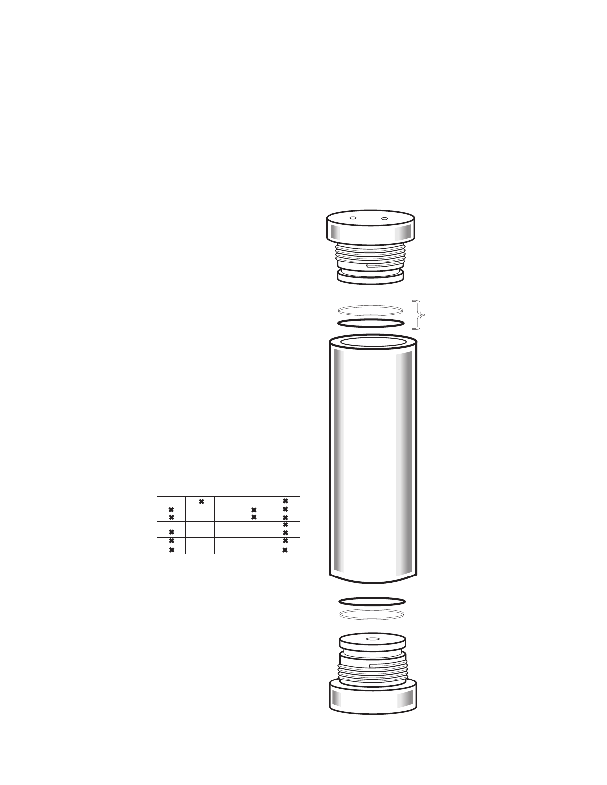
Cartridge Holder / Model PU-960003-AF
PU-960003-AF Holder
PRECAUTIONS: Follow safe engineering practices when installing or servicing this assembly. Depressurize system
and dis-connect electrical supplies prior to any service action. Do not over tighten cylinder head or foot. Do not exceed
working conditions set forth herein.
INSTALLATION: Mount to solid foundation in upright position (optional mounting kit is available). Gas flow through
unit must be in direction of arrow imprint on cylinder foot. Use appropriate thread sealant when making connections.
Apply nameplate, when installation is complete.
Use extreme care to prevent internal contamination since this unit has bee prepared for hyper clean environment.
SPECIFICATIONS
STYLE
MODEL NO
WORKING PRESSURE
MAXIMUM PRESSURE
TEST PRESSURE
BURST PRESSURE
SAFETY FACTOR
REPRESSURE CYCLE LIFE
MINIMUM TEMPERATURE
MAXIMUM TEMPERATURE
DIMENSIONS
PORT SIZE
CARTRIDGE SUPPLIED
Cartridge Holder
PU-960003-AF
2,000 - 5,000 PSI
5,000 PSI
7,500 PSI
20,000 PSI
4:1 ASME
15,000
0
40 F
0
120 F
3.750"OD x 33" H
No. 6-AN
Specified by application
CYLINDER HEAD
NOT AVAILABLE SEPARATELY
SEAL KIT
Part No. Sk-535306-BB
SEAL KIT
Part No. SK-535306-BB
CYLINDER
NOT AVAILABLE SEPARATELY
CYLINDER FOOT
NOT AVAILABLE SEPARATELY
Upon
demand
MAINTENANCE SCHEDULE
Replace FILTER ELEMENT
Lubricate O-RING SEALS
Apply grease to CYLINDER HEADS AND FEET
Replace O-RING SEALS
Inspect all PIPING JOINTS for leakage
Inspect all SEAL JOINTS and COMPONENTS for leaks
Inspect CYLINDER wall conditions
Replace CARTRIDGE HOLDER at limits of cycle life
Always employ safe practices in handling volatile or respiratory gases. Wear protective gear when
installing, operating, or servicing compressed gas apparatus. Never smoke, cause sparks or fire, or
switch electrical equipment while in the presence of volatile gases. MSDS are available for materials
contained in disposable cartridges. Never exceed ratings for this equipment.
Always depressurize this equipment prior to any service activity. Do not direct compressed gases at
bodily openings, eyes, or skin.
EVERY 15,000 CYCLES
Anytime
service is
performed
Monthly Every
3 months
Every
6 months


High Purity At High Pressure
4740 NW 157 Street, Miami Lakes, FL 33014 U.S.A.
Phone: (305) 430-0550 Fax: (305) 430-0864 Toll Free: (800) 338-5493
Email: [email protected] Website: www.Lawrence-Factor.com
Table of contents


