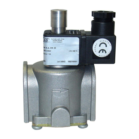
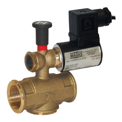
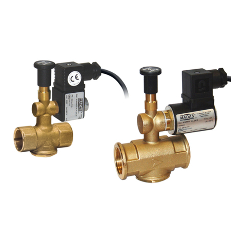
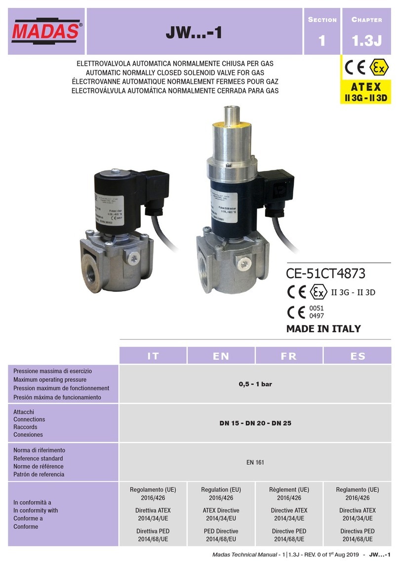
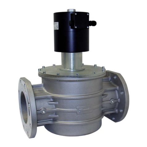
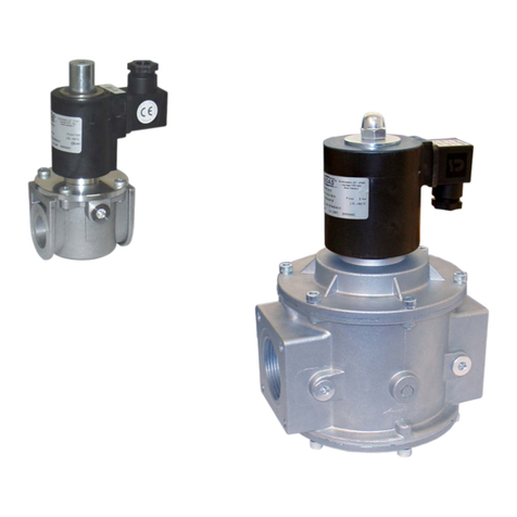
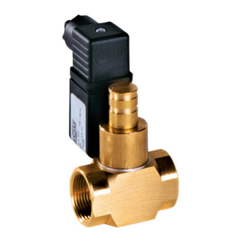
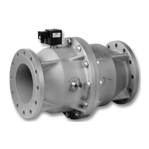
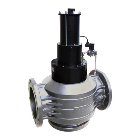
Madas EVP/NC User manual

EVP/NC
DESCRIPTION
Gasinterceptionautomaticnormallyclosedsolenoid
valvesthatopenwhenthecoilispoweredandclose
when there is no tension.
Thesesolenoidvalvescanbecontrolledbypressure
switch, thermostat, etc.
They can be equipped with a flo w r e g u l a t o r a n d
adjustable slow opening kit.
EC certifie d a c c o r d i n g t o E N 1 6 1
In conformity with the 2009/142/EC
Directive (Gas Directive)
In conformity with the 94/9/EC Directive
(ATEX Directive)
Inconformity withthe 2004/108/ECDirective
(Electromagnetic Compatibility)
Inconformitywiththe2006/95/ECDirective
(Low Voltage)
II 3G - II 3D
MADAS-01
0051

TECHNICAL DATA
• Use:
not aggressive gases of the 3 families
(dry gases)
• Threaded connections Rp:
(DN 15 ÷ DN 50) according to EN 10226
• Flanged connections PN 16:
(DN 25 ÷ DN 200) according to ISO 7005
• On request ANSI 150 fla n g e d c o n n e c t i o n s
• Power supply voltage
(see table)
• Power supply voltage tolerance:
-15% ... +10%
• Power absorption:
see coils and connector table
• Max. working pressure:
(DN 15 ÷ DN 50) 200 or 360 mbar
(DN 65 ÷ DN 150) 360 mbar
• Environment temperature:
-15 ÷ +60 °C
• Max superfic i a l t e m p e r a t u r e :
85 °C
• Protection degree:
IP65
• Class:
DN 15 ÷ DN 150: A
DN 200: B
• Group:
2
• Closing time:
<1 s
• Opening time:
<1 s
Coils:poliammidicresinencapsulatedwithglass
fib r e , c o n n e c t i o n t y p e D I N 4 3 6 5 0 ; t h e i n s u l a t i o n
class is F (155°) and the enamelled copper wire
class is H (180°).
Coils(EVPDN32÷DN150):theinsulationclass
andtheenamelledcopperwireclassisH(180°).
MATERIALS
• Die-cast aluminium (UNI EN 1706)
•OT-58 brass (UNI EN 12164)
• 11S aluminium (UNI 9002-5)
• galvanized and 430 F stainless steel(UNI EN
10088)
• NBR rubber (UNI 7702)
• nylon 30% glass fib r e
(UNI EN ISO 11667)
• viledon

Manuale Tecnico 2011
Capitolo 2 (Rev. 0)
ELETTROVALVOLE NORMALMENTE CHIUSE AUTOMATICHE TIPO EVP/NC - EVPC/NC
EVP/NC - EVPC/NC AUTOMATIC NORMALLY CLOSED SOLENOID VALVES
ELECTROVANNES NORMALEMENT FERMEES AUTOMATIQUES DE TYPE EVP/NC - EVPC/NC
ELECTROVÁLVULAS NORMALMENTE CERRADAS AUTOMÁTICAS TIPO EVP/NC - EVPC/NC
62011 Technical Manual
Chapter 2 (Rev. 0) Manuel Technique 2011
Chapitre 2 (Rev. 0) Manual Técnico 2011
Capítulo 2 (Rev. 0)
EVP/NC
EVPC/NC
© 2011 MADAS s.r.l.
Capitolo - Chapter
Chapìtre - Capitulo
2
2
Foto
Photo
Photo
Fotos
Attacchi
Connections
Fixations
Conexiones
Voltaggio
Voltage
Voltage
Voltaje
Attacchi Filettati - Threaded Connections
Fixations filetees - Conexiones roscadas
Attacchi Flangiati - Flanged Connections
Fixations Bridees - Conexiones de Brida
P.max 360 mbar P.max 360 mbar
Codice - Code
Code - Código Codice - Code
Code - Código
EVP/NC
DN 32
12 Vdc EVP05 001 EVP32 001
24 Vdc EVP05 005 EVP32 005
24 V/50 Hz EVP05 003 EVP32 003
110 V/50 Hz EVP05 002 EVP32 002
230 V/50-60 Hz EVP05 008 EVP32 008
EVP/NC
DN 40
12 Vdc EVP06 001 EVP40 001
24 Vdc EVP06 005 EVP40 005
24 V/50 Hz EVP06 003 EVP40 003
110 V/50 Hz EVP06 002 EVP40 002
230 V/50-60 Hz EVP06 008 EVP40 008
EVP/NC
DN 50
12 Vdc EVP07 001 EVP50 001
24 Vdc EVP07 005 EVP50 005
24 V/50 Hz EVP07 003 EVP50 003
110 V/50 Hz EVP07 002 EVP50 002
230 V/50-60 Hz EVP07 008 EVP50 008
EVP/NC
DN 65
24 Vdc - EVP08 005
24 V/50 Hz - EVP08 003
110 V/50 Hz - EVP08 002
230 V/50-60 Hz - EVP08 008
EVP/NC
DN 80
24 Vdc - EVP09 005
24 V/50 Hz - EVP09 003
110 V/50 Hz - EVP09 002
230 V/50-60 Hz - EVP09 008
EVP/NC
DN 100
24 Vdc - EVP10 005
24 V/50 Hz - EVP10 003
110 V/50 Hz - EVP10 002
230 V/50-60 Hz - EVP10 008
EVP/NC
DN 125
24 Vdc - EVP11 005
24 V/50 Hz - EVP11 003
110 V/50 Hz - EVP11 002
230 V/50-60 Hz - EVP11 008
EVP/NC
DN 150
24 Vdc - EVP12 005
24 V/50 Hz - EVP12 003
110 V/50 Hz - EVP12 002
230 V/50-60 Hz - EVP12 008
EVP/NC
DN 200
24 Vdc - EVP13 005
24 V/50 Hz - EVP13 003
110 V/50 Hz - EVP13 002
230 V/50-60 Hz - EVP13 008
con regolatore di portata = EVPF....
with flow regulator = EVPF....
avec régulateur de portée = EVPF....
con regulador de caudal = EVPF....

fig . 5 a n d 6
1. Electrical connector
2. Seal O-Ring
3. Closing spring
4. Body valve
5. Obturator
6. Seal washer
7. G 1/4” cap
8. Filter
9. Fixing screws
10. Cover or bottom
11. Electrical coil
12. Coil fix i n g n u t o r s c r e w
13. Flow calibration screw (EVPF version)
14. Bottom (only on DN 65-80-100)
fig . 6
EVP/NC DN 65÷150
P.max 360 mbar

Capacity diagram EVP/NC P.max 360 mbar
1) metano
2) aria
3)gasdicittà
4) gpl
1) methane
2) air
3) town gas
4) lpg
e
e
n
e
o

INSTALLATION
The solenoid valve is in conformity with
the Directive 94/9/CE (said Directive ATEX
100 a) as device of group II, category 3G
and as device of group II, category 3D;
for this reason it is suitable to be installed
in the zones 2 and 22 as classifie d i n t h e
attachment I to the Directive 99/92/EC. The
solenoid valve is not suitable to be used
in zones 1 and 21 and, all the more so, in
zones 0 and 20 as classifie d i n t h e a l r e a d y
said Directive 99/92/EC.
To determine the qualific a t i o n a n d t h e
extension of the dangerous zones, see the
norm EN 60079-10.
The device, if installed and serviced
respecting all the conditions and the
technical instructions of this document, is
not source of specific d a n g e r s : i n p a r t i c u l a r,
during the normal working, is not forecast,
by the solenoid valve, the emission in the
atmosphere of infla m m a b l e s u b s t a n c e i n
way to cause an explosive atmosphere.
WARNING: all installation/wiring/
maintenance work must be carried out
by skilled staff.
• The gas supply must be shut off before
installation.
• Check that the line pressure DOES NOT
EXCEED the maximum pressure stated
on the product label.
It is always important to read
carefully the instruction sheet of
each product.
Overall dimensions in mm
Flanged
connections F P. max
(mbar) A
B
EVP...
EVPC...
- 70 137 05 185
- 200 / 360 70 137 150 205 185
- 360 mbar 90 157 172 225 205
- EVPC DN 25 200 / 360 142 170 195 250 230
- EVP DN 25 360 mbar 162 190 205 262 242
- 200 mbar 160 185 200 262 240
- 360 mbar 160 210 210 275 253
- 200 mbar 160 210 225 290 267
- 360 mbar 160 210 225 290 267
EVPC DN 32 - DN 40 - DN 50 200 / 360 230 237 252 295 269
EVP DN 50 - 360 mbar 160 235 235 300 278
EVP DN 32 - DN 40 - DN 50 360 mbar 230 261 261 326 304
- EVP DN 65 360 mbar 290 321 321 480 432
- EVP DN 80 360 mbar 310 328 328 486 439
- EVP DN 100 360 mbar 350 389 389 547 500
- EVP DN 125 360 mbar 480 570 570 728 681
- EVP DN 150 360 mbar 480 570 570 728 681
EVP DN 200 360 mbar 600 680 680 - -

• They must be installed with the arrow (on
the body of the device) facing towards
the user appliance. Except DN 200 they
will function equally effectively if installed
vertical. They must not be installed upside
down (with the coil underneath).
• During installation take care not to allow
debris or scraps of metal to enter the
device.
• If the device is threaded check that the
pipeline thread is not too long; overlong
threads may damage the body of the
device when screwed into place. Do not
use the coil for leverage when screwing
into position; use the appropriate tool.
• If the device is fla n g e d c h e c k t h a t t h e i n l e t
and outlet counterfla n g e s a r e p e r f e c t l y
parallel to avoid unnecessary mechanical
stresses on the body of the device. Also
calculate the space needed to fit t h e s e a l .
If the gap left after the seal is fit t e d i s
too wide, do not try to close it by over-
tightening the device’s bolts.
• Always check that the system is gas-tight
after installation.
• Except DN 200 in the version with flo w
regulator (EVPF... - EVPCF...) unscrew the
nut (12) and set the wanted value of the
gasfl o w b y t h e r e g u l a t i o n s c r e w ( 13).Then
rescrewthenut(12)intheoriginalposition.
CALIBRATIONS (DN 15 ÷ DN 150)
• To regulate the opening speed of the
obturator operate on the screw (16).
This screw has not limit, the opening
speed increases gradually screwing
clockwise the screw (16).
• To regulate the rapide stroke operate on the
screw (15). Screwing counterclockwise
till the limit, the opening of the valve will
be slow at fir s t , s c r e w i n g i t c l o c k w i s e y o u
get a fir s t p h a s e o f s p e e d o p e n i n g a n d a
second slow one.
• To regulate the flo w o p e r a t e o n t h e s c r e w
(14). Screwing it clockwise in order to
decrease the flow, counterclockwise in
order to increase it.
ELECTRICAL CONNECTIONS
• Before making electrical connections, check
that the mains voltage is the same as
the power supply voltage stated on the
product label.
• Disconnect the power supply before wiring.
• Wire the connector with cable type:
EVP... DN 15 ÷ DN 25
EVPC... DN 25 ÷ DN 50
EVP... DN 200
H05RN-F 3X0,75mm², Ø outside from 6,2 to 8,1 mm
EVP... DN 32 ÷ DN 150
H05RN-F 3X1 mm², Ø outside from 8,3 to 9,5 mm
taking care to ensure that the device has IP65
protection.
• Connect the power supply to terminals 1 and
2 and the ground wire to terminal .
IMPORTANT: with tension 12 Vdc and
24 Vdc with energy saving connector CN-
21... observe the polarity.
The coil is also suitable for permanent power
supply. In case of continuous duty, it is
absolutely normal for the coil to heat up. The
coil should not be touched with bare hands
after it has been continuously powered for
more than 20 minutes. Before maintenance
work, wait for the coil to cool or use suitable
protective equipment.

EXAMPLE OF INSTALLATION 1
1. M16/RM N.C. manual reset solenoid valve
2. SM series jerk handle ON/OFF valve
3. Gas fil t e r t y p e F M
4. Gas pressure regulator type RG/2MC
5. Automatic solenoid valve type
EVP/NC or EVPC/NC
6. Solenoid valve control device
7. Manometer
8. Gas detector
9. Lever for remote SM ON/OFF valve control
rete - pipe
réseau - red utenza - user
utilisateur - punto de consumo
rete - pipe
réseau - red
EXAMPLE OF INSTALLATION 2
1. Gas fil t e r t y p e F M
2. Over pressure slam shut off valve type
MVB1/MAX
3. Gas pressure regulator type RG/2MC
4. PressureswitchofminimumpressuretypeMP
5. Automatic solenoid valve type
EVP or EVPC
6. Automatic solenoid valve type
EVP or EVPC
7. External reset
8. Burner control
9. Valve proving system type MTC10
10. Manometer
testa di combustione
combustion head
tête de combustion
cabeza de combustión

The above-said operations must
be carried out only by qualifie d
technicians.
9
19
19
SERVICING
In all cases, before performing any internal
checks make sure that:
1.the power supply to the device is
disconnected
2.there is no pressurised gas inside the device
• DN 15 ÷ DN 25: (see fi g . 1 a n d 2 ) u n s c r e w
the coil fix i n g s c r e w s ( 12) (or the slow
opening kit (17)) and remove the coil
(11). Unscrew the cover fixing screws
(9) and disassemble it from body valve
(4). Check the obturator (5), clean or if is
necessary sobstitute the rubber made seal
component. Clean the fil t e r ( 8) blowing it
without taking it off the body valve (4).
Then assemble doing backward the same
operation of dismantling.
• DN32÷DN150:(seefi g . 3 , 4 , 5 , 6 ) u n s c r e w
thenut (12) (orthe slow openingkit (17))
and remove the coil (11). Unscrew the
fix i n g s c r e w s ( 9) and, with care, take the
cover (10) off the body (4) of the valve,
then control the obturator (5) and if it is
necessary change the rubber made seal
component(6).Thencleanorblowthefi l t e r
(8)orchangeitifnecessary;thenassemble
doing backward the same operation.
VIEW: BODY OF THE VALVE WITHOUT
COVER
TO INSERT THE NET
DN 32 ÷ DN 50:
Positionitasinthefi g u r e t a k i n g c a r e t o r e s p e c t
the guides in the internal circumference of
the body valve and fix i t b y t h e t h r e e s p e c i a l
screws (M3x10).
TO INSERT THE FILTERING ORGAN:
DN 65 ÷ DN 100:
Position it as in the fig u r e t a k i n g c a r e t o p u t
it inside the guides (18).
DN 125 - DN 150:
Putitasin fig u r e , s o t h a t t h e s p e c i a l fin s ( 19)
are leant against the body. So reassemble
the cover paying attention that the O-Ring
is into the right hole.
18
8
8
fig . 5

Bobine e connettori - Coils and connectors
Bobines et connecteurs - Bobinas y conectores
Attacchi
Connections
Voltaggio
Voltage
Codice
bobina
Coil code
Timbratura
bobina
Coil
stamping
Codice
connettore
Connector
code
Tipo connettore
Connector type
EVP/NC - EVPF/NC
DN 15 - DN 20
(P.max 200 mbar)
12 Vdc BO-0400 BO-0400
12 VDC 17W CN-0010 NORMALE
NORMAL
12 V/50 Hz BO-0400 BO-0400
12 VDC 17W CN-0050
RADDRIZZATORE -
RECTIFIER
24 Vdc BO-0410 BO-0410
24 VDC 17W CN-0010 NORMALE
NORMAL
24 V/50 Hz BO-0410 BO-0410
24 VDC 17W CN-0050
RADDRIZZATORE
RECTIFIER
110 V/50-60 Hz BO-0420 BO-0420
110 V RAC 17W CN-0045
RADDRIZZATORE
RECTIFIER
230 V/50-60 Hz BO-0430 BO-0430
230 V RAC 17W CN-0045
RADDRIZZATORE
RECTIFIER
EVP/NC - EVPF/NC DN 15 - DN 20
(P.max 360 mbar)
EVPC/NC - EVPCF/NC DN 25
(P.max 200 mbar)
12 Vdc BO-0510 BO-0510
12 VDC 28W CN-2100 NORMALE + Energy Saving
NORMAL + Energy Saving
12 V/50 Hz BO-0510 BO-0510
12 VDC 28W CN-2110
RADDRIZZATORE
+ Energy Saving
RECTIFIER + Energy Saving
24 Vdc BO-0520 BO-0520
24 VDC 28W CN-2100 NORMALE + Energy Saving
NORMAL + Energy Saving
24 V/50 Hz BO-0520 BO-0520
24 VDC 28W CN-2110
RADDRIZZATORE
+ Energy Saving
RECTIFIER + Energy Saving
110 V/50-60 Hz BO-0530 BO-0530
110 V RAC 28W CN-2130
RADDRIZZATORE
+ Energy Saving
RECTIFIER
+ Energy Saving
230 V/50-60 Hz BO-0540 BO-0540
230 V RAC 28W CN-2130
RADDRIZZATORE
+ Energy Saving
RECTIFIER + Energy Saving
EVPC/NC - EVPCF/NC DN 25
(P.max 360 mbar)
12 Vdc BO-0407 BO-0407
12V RAC ES CN-2100 NORMALE + Energy Saving
NORMAL + Energy Saving
12 V/50 Hz BO-0407 BO-0407
12V RAC ES CN-2110
RADDRIZZATORE
+ Energy Saving
RECTIFIER + Energy Saving
24 Vdc BO-0417 BO-0417
24V RAC ES CN-2100 NORMALE + Energy Saving
NORMAL + Energy Saving
24 V/50 Hz BO-0417 BO-0417
24V RAC ES CN-2110
RADDRIZZATORE
+ Energy Saving
RECTIFIER + Energy Saving
110 V/50-60 Hz BO-0427 BO-0427
110V RAC ES CN-2130
RADDRIZZATORE
+ Energy Saving
RECTIFIER
+ Energy Saving
230 V/50-60 Hz BO-0437 BO-0437
230V RAC ES CN-2130
RADDRIZZATORE
+ Energy Saving
RECTIFIER + Energy Saving
EVP/NC - EVPF/NC DN 25
(P.max 360 mbar)
12 Vdc BO-0290 BO-0290
12 VDC W44 CN-2100 NORMALE + Energy Saving
NORMAL + Energy Saving
12 V/50 Hz BO-0290 BO-0290
12 VDC W44 CN-2110
RADDRIZZATORE
+ Energy Saving
RECTIFIER + Energy Saving
24 Vdc BO-0300 BO-0300
24 VDC W45 CN-2100 NORMALE + Energy Saving
NORMAL + Energy Saving
24 V/50 Hz BO-0300 BO-0300
24 VDC W45 CN-2110
RADDRIZZATORE
+ Energy Saving
RECTIFIER + Energy Saving
110 V/50-60 Hz BO-0310 BO-0310
V 98 DC W45 CN-2130
RADDRIZZATORE
+ Energy Saving
RECTIFIER
+ Energy Saving
230 V/50-60 Hz BO-0320 BO-0320
V 196 DC W45 CN-2130
RADDRIZZATORE
+ Energy Saving
RECTIFIER + Energy Saving
EVPC/NC - EVPCF/NC DN 32 - DN 40 - DN 50
(P.max 200 / 360 mbar)
24 Vdc BO-0355 BO-0355
24V RAC ES CN-2100 NORMALE + Energy Saving
NORMAL + Energy Saving
24 V/50 Hz BO-0355 BO-0355
24V RAC ES CN-2110
RADDRIZZATORE
+ Energy Saving
RECTIFIER + Energy Saving
110 V/50-60 Hz BO-0365 BO-0365
110 V RAC ES CN-2130
RADDRIZZATORE
+ Energy Saving
RECTIFIER
+ Energy Saving
230 V/50-60 Hz BO-0375 BO-0375
230 V RAC ES CN-2130
RADDRIZZATORE
+ Energy Saving
RECTIFIER + Energy Saving
Per le bobine e connettori di ricambio dei modelli Q - R - S - T - contattare il ns uffic i o t e c n i c o .
For coils and connectors of Q - R - S - T models as spares, please contact our technical department.

Bobine e connettori - Coils and connectors
Bobines et connecteurs - Bobinas y conectores
Attacchi
Connections
Voltaggio
Voltage
Codice bobina completa
di connettore
Coil code
complete with
connector
Timbratura
bobina
Coil
stamping
Codice solo
connettore
Connector
code only
Tipo connettore
Connector type
DN 32 - DN 40 - DN 50
(P.max 360 mbar)
12 Vdc BO-1000 12 Vdc DN 32 - 40 - 50 CN-2000 NORMALE
NORMAL
24 Vdc BO-1010 24 Vdc DN 32 - 40 - 50 CN-2000 NORMALE
NORMAL
24 V/50 Hz BO-1015 24 Vac DN 32 - 40 - 50 CN-2010
RADDRIZZATORE
+ Energy Saving
RECTIFIER + Energy Saving
110 V/50-60 Hz BO-1020 110 Vac DN 32 - 40 - 50 CN-2020
RADDRIZZATORE
+ Energy Saving
RECTIFIER
+ Energy Saving
230 V/50-60 Hz BO-1030 230 Vac DN 32 - 40 - 50 CN-2030
RADDRIZZATORE
+ Energy Saving
RECTIFIER + Energy Saving
DN 65 ÷ DN 80
(P.max 360 mbar)
24 Vdc BO-1110 24 Vdc DN 65 - 80 CN-2000 NORMALE
NORMAL
24 V/50 Hz BO-1115 24 Vac DN 65 - 80 CN-2010
RADDRIZZATORE
+ Energy Saving
RECTIFIER + Energy Saving
110 V/50-60 Hz BO-1120 110 Vac DN 65 - 80 CN-2020
RADDRIZZATORE
+ Energy Saving
RECTIFIER
+ Energy Saving
230 V/50-60 Hz BO-1130 230 Vac DN 65 - 80 CN-2030
RADDRIZZATORE
+ Energy Saving
RECTIFIER + Energy Saving
DN 100 ÷ DN 150
(P.max 360 mbar)
24 Vdc BO-1210 24 Vdc DN 100 CN-2000 NORMALE
NORMAL
24 V/50 Hz BO-1215 24 Vac DN 100 CN-2010
RADDRIZZATORE
+ Energy Saving
RECTIFIER + Energy Saving
110 V/50-60 Hz BO-1220 110 Vac DN 100 CN-2020
RADDRIZZATORE
+ Energy Saving
RECTIFIER
+ Energy Saving
230 V/50-60 Hz BO-1230 230 Vac DN 100 CN-2030
RADDRIZZATORE
+ Energy Saving
RECTIFIER + Energy Saving
Per le bobine e connettori di ricambio dei modelli Q - R - S - T - contattare il ns uffic i o t e c n i c o .
For coils and connectors of Q - R - S - T models as spares, please contact our technical department.
Other manuals for EVP/NC
1
Table of contents
Other Madas Control Unit manuals

Madas
Madas EVAP-1-3-6/NA User manual

Madas
Madas EV-1 User manual

Madas
Madas M16/RMO N.C. User manual

Madas
Madas M16/RMJ N.A. User manual

Madas
Madas M16/RMO NA/NC User manual

Madas
Madas MP16/RM N.A. DN 15 User manual

Madas
Madas EV-1 User manual

Madas
Madas M16/RMOJ N.A. User manual
Madas
Madas MVB/1 MAX User manual

Madas
Madas EVP/NC User manual

Madas
Madas EVQ-1 EEX User manual

Madas
Madas M16/RMOX N.A. User manual

Madas
Madas XVR-1-3-6 User manual

Madas
Madas MBV Series User manual

Madas
Madas M16/RM N.A. User manual

Madas
Madas M16/RMC N.A. User manual

Madas
Madas JW-1 Series User manual
Madas
Madas M16/RMO NA/NC User manual
Madas
Madas CE-51CN4180 User manual

Madas
Madas M16/RMX N.A. User manual