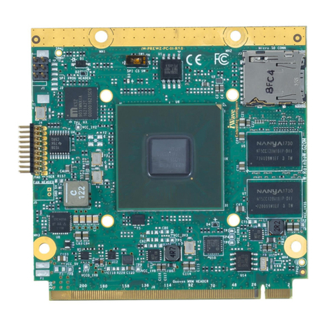
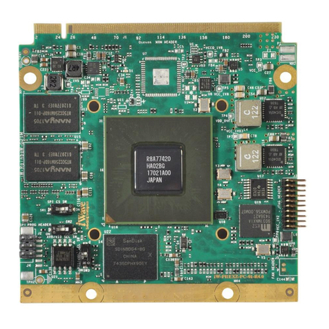
iWave iW-RainboW-G53M Installation manual

iW-G53M-Renesas RZ/G2UL or RZ/FIVE or RZ/A3UL based OSM Hardware User Guide
iWave Systems Technologies Pvt. Ltd.
REL0.1
Page 1 of 66
DRAFT VERSION SUBJECT TO CHANGE WITHOUT NOTICE
iW-RainboW-G53M
RZ/G2UL or RZ/FIVE or RZ/A3UL
OSM Size-MF Hardware User Guide

iW-G53M-Renesas RZ/G2UL or RZ/FIVE or RZ/A3UL based OSM Hardware User Guide
iWave Systems Technologies Pvt. Ltd.
REL0.1
Page 2 of 66
DRAFT VERSION SUBJECT TO CHANGE WITHOUT NOTICE
Document Revision History
Document Number
iW-PRHGZ-UM-01-R1.0-REL0.1-Hardware
Revision
Date
Description
0.1
05th May 2023
Draft Release Version
PROPRIETARY NOTICE: This document contains proprietary material for the sole use of the intended recipient(s). Do
not read this document if you are not the intended recipient. Any review, use, distribution or disclosure by others is
strictly prohibited. If you are not the intended recipient (or authorized to receive for the recipient), you are hereby
notified that any disclosure, copying distribution or use of any of the information contained within this document is
STRICTLY PROHIBITED. Thank you. “iWave Systems Tech. Pvt. Ltd.”

iW-G53M-Renesas RZ/G2UL or RZ/FIVE or RZ/A3UL based OSM Hardware User Guide
iWave Systems Technologies Pvt. Ltd.
REL0.1
Page 3 of 66
DRAFT VERSION SUBJECT TO CHANGE WITHOUT NOTICE
Disclaimer
iWave Systems reserves the right to change details in this publication including but not limited to any Product
specification without notice.
No warranty of accuracy is given concerning the contents of the information contained in this publication. To the
extent permitted by law no liability (including liability to any person by reason of negligence) will be accepted by iWave
Systems, its subsidiaries or employees for any direct or indirect loss or damage caused by omissions from or
inaccuracies in this document.
SoC and other major components used in this product may have several silicon errata associated with it. Under no
circumstances, iWave Systems shall be liable for the silicon errata and associated issues.
Trademarks
All registered trademarks, product names mentioned in this publication are the property of their respective owners
and used for identification purposes only.
Certification
iWave Systems Technologies Pvt. Ltd. is an ISO 9001:2015 Certified Company.
Warranty & RMA
Warranty support for Hardware: 1 Year from iWave or iWave's EMS partner.
For warranty terms, go through the below web link,
http://www.iwavesystems.com/support/warranty.html
For Return Merchandise Authorization (RMA), go through the below web link,
http://www.iwavesystems.com/support/rma.html
Technical Support
iWave Systems technical support team is committed to provide the best possible support for our customers so that
our Hardware and Software can be easily migrated and used.
For assistance, contact our Technical Support team at,
Email : support.ip@iwavesystems.com
Website : www.iwavesystems.com
Address : iWave Systems Technologies Pvt. Ltd.
# 7/B, 29th Main, BTM Layout 2nd Stage,
Bengaluru, Karnataka,
India –560076

iW-G53M-Renesas RZ/G2UL or RZ/FIVE or RZ/A3UL based OSM Hardware User Guide
iWave Systems Technologies Pvt. Ltd.
REL0.1
Page 4 of 66
DRAFT VERSION SUBJECT TO CHANGE WITHOUT NOTICE
Table of Contents
1. INTRODUCTION ............................................................................................................................................7
1.1 Purpose .............................................................................................................................................................7
1.2 OSM LGA Module Overview .............................................................................................................................7
1.3 List of Acronyms................................................................................................................................................7
1.4 Terminology Description...................................................................................................................................9
1.5 References ........................................................................................................................................................9
1.6 Important Note ...............................................................................................................................................10
2. ARCHITECTURE AND DESIGN....................................................................................................................... 11
2.1 RZ/G2UL,RZ/FIVE and RZ/A3UL OSM LGA Module Block Diagram.................................................................11
2.2 RZ/G2UL, RZ/FIVE and RZ/A3UL SOM Features.............................................................................................12
2.3 RZ/G2UL or RZ/FIVE or RZ/A3UL MPU............................................................................................................14
2.4 PMIC with RTC.................................................................................................................................................17
2.5 Memory...........................................................................................................................................................18
2.5.1 DDR4 RAM...................................................................................................................................................18
2.5.2 eMMC Flash ................................................................................................................................................18
2.6 OSM LGA/BGA Balls ........................................................................................................................................19
2.6.1 RGMII Interface...........................................................................................................................................32
2.6.2 SD Interface.................................................................................................................................................35
2.6.3 SPI Interface ................................................................................................................................................36
2.6.4 CAN Interface ..............................................................................................................................................37
2.6.5 USB2.0 OTG Interface..................................................................................................................................38
2.6.6 USB2.0 Host Interface .................................................................................................................................38
2.6.7 I2C Interface................................................................................................................................................40
2.6.8 Data UART...................................................................................................................................................41
2.6.9 Debug Console UART...................................................................................................................................41
2.6.10 PWM Interface ............................................................................................................................................42
2.6.11 ADC Interface ..............................................................................................................................................42
2.6.12 JTAG Interface .............................................................................................................................................43
2.6.13 RGB Display interface..................................................................................................................................44
2.6.14 MIPI CSI Camera Interface ..........................................................................................................................46
2.6.15 OSM GPIOs ..................................................................................................................................................47
2.6.16 Control Signals ............................................................................................................................................48
2.6.17 Vendor Defined............................................................................................................................................48
2.6.18 Boot Media Selection ..................................................................................................................................49
2.6.19 Power and GND...........................................................................................................................................50
2.7 Other Features................................................................................................................................................52
2.7.1 Programming Header..................................................................................................................................52
2.8 RZ/G2UL, RZ/FIVE and RZ/A3UL Pin Multiplexing on OSM BGA....................................................................53
3. TECHNICAL SPECIFICATION.......................................................................................................................... 60
3.1 Electrical Characteristics .................................................................................................................................60

iW-G53M-Renesas RZ/G2UL or RZ/FIVE or RZ/A3UL based OSM Hardware User Guide
iWave Systems Technologies Pvt. Ltd.
REL0.1
Page 5 of 66
DRAFT VERSION SUBJECT TO CHANGE WITHOUT NOTICE
3.1.1 Power Input Requirement ...........................................................................................................................60
3.1.2 Power Consumption ....................................................................................................................................61
3.2 Environmental Characteristics........................................................................................................................62
3.2.1 Environmental Specification........................................................................................................................62
3.2.2 Heat Sink/ Heat Spreader............................................................................................................................62
3.2.3 RoHS Compliance ........................................................................................................................................63
3.2.4 Electrostatic Discharge................................................................................................................................63
4. ORDERING INFORMATION .......................................................................................................................... 64
5. APPENDIX................................................................................................................................................... 65
5.1 Renesas RZ/G2UL, RZ/FIVE and RZ/A3UL SBC ................................................................................................65

iW-G53M-Renesas RZ/G2UL or RZ/FIVE or RZ/A3UL based OSM Hardware User Guide
iWave Systems Technologies Pvt. Ltd.
REL0.1
Page 6 of 66
DRAFT VERSION SUBJECT TO CHANGE WITHOUT NOTICE
List of Figures
Figure 1: Renesas RZ/G2UL, RZ/FIVE or RZ/A3UL OSM LGA Block Diagram................................................................... 11
Figure 2: RZ/G2UL MPU Block Diagram .......................................................................................................................... 14
Figure 3: RZ/FIVE MPU Block Diagram............................................................................................................................ 15
Figure 4: RZ/A3UL MPU Block Diagram .......................................................................................................................... 16
Figure 5: OSM LGA/BGA Balls ......................................................................................................................................... 19
List of Tables
Table 1: Acronyms & Abbreviations.................................................................................................................................. 7
Table 2: Terminology ........................................................................................................................................................ 9
Table 3: OSM Pinouts...................................................................................................................................................... 20
Table 4: RZ/G2UL, RZ/FIVE and RZ/A3UL MPU for OSM BGA interfaces........................................................................ 53
Table 5: Power Input Requirement................................................................................................................................. 60
Table 6: Environmental Specification ............................................................................................................................. 62
Table 7: Orderable Product Part Numbers ..................................................................................................................... 64

iW-G53M-Renesas RZ/G2UL or RZ/FIVE or RZ/A3UL based OSM Hardware User Guide
iWave Systems Technologies Pvt. Ltd.
REL0.1
Page 7 of 66
DRAFT VERSION SUBJECT TO CHANGE WITHOUT NOTICE
1. INTRODUCTION
1.1 Purpose
This document is the Hardware User Guide for the Renesas’s RZ/G2UL, RZ/FIVE and RZ/A3UL Application processor
based on OSM v1.1 specification based LGA module. This board is fully supported by iWave Systems Technologies Pvt.
Ltd. This Guide provides detailed information on the overall design and usage of the Renesas’s RZ/A3UL, G2UL and
FIVE OSM Module from a Hardware Systems perspective.
1.2 OSM LGA Module Overview
The OSM V1.1 (“Open Standard Modules™”) is a future proof and versatile standard for small size, low-cost embedded
computer modules. Combining the key characteristics like completely machine processible during soldering, assembly
and testing, Pre-tinned LGA package for direct PCB soldering without connector.
The OSM Module definition targeting application that requires low power, low costs, and high performance. The
Modules are used as building blocks for portable and stationary embedded systems. The core SoC and support circuits,
including DRAM, boot flash, power sequencing, SoC power supplies are concentrated on the Module. The Modules
are used with application specific Carrier Boards that implement other features such as audio CODECs, touch
controllers, wireless devices, etc. The modular approach allows scalability, fast time to market and upgradability while
still maintaining low costs, low power and small physical size.
Renesas’s RZ/G2UL, RZ/FIVE and RZ/A3UL based OSM LGA Module is rich with Renesas features along with on SOM
DDR4, eMMC and comes in compact 30mm x 45mm form factor (OSM Size M). The Module PCB has 476 contacts
which can be mounted as LGA/BGA on the OSM Carrier Card.
1.3 List of Acronyms
The following acronyms will be used throughout this document.
Table 1: Acronyms & Abbreviations
Acronyms
Abbreviations
ARM
Advanced RISC Machine
CAN
Controller Area Network
CODEC
Coder-Decoder
CPU
Central Processing Unit
CSI
Camera Serial Interface
CTS
Clear to Send
DRAM
Dynamic Random Access Memory
DSI
Display Serial Interface
DC
Direct current
eMMC
Enhanced Multi Media Card

iW-G53M-Renesas RZ/G2UL or RZ/FIVE or RZ/A3UL based OSM Hardware User Guide
iWave Systems Technologies Pvt. Ltd.
REL0.1
Page 8 of 66
DRAFT VERSION SUBJECT TO CHANGE WITHOUT NOTICE
Acronyms
Abbreviations
EMS
Electronics manufacturing services
EMC
Electromagnetic Compatibility
EMI
Electromagnetic Interference
FLEXCAN
Flexible Control Area Network
GB
Giga Byte
Gbps
Gigabits per sec
GPIO
General Purpose Input Output
I2C
Inter-Integrated Circuit
IC
Integrated Circuit
JTAG
Joint Test Action Group
MHz
Mega Hertz
MB
Mega Byte
Mbps
Mega Bits Per Second
MIPI
Mobile Industry Processor Interface
mm
millimetre
MMC
Multi Media Card Interface
NA
Not Applicable
OSM
Open Standard Module
OTG
On-The-Go
PCB
Printed Circuit Board
PMIC
Power Management Integrated circuit
PWM
Pulse Width Modulation
RAM
Random Access Memory
REACH
Regulation Evaluation Authorization of Chemical Substances
RGMII
Reduced gigabit media-independent interface
RIIC
Rx family Inter Integrated Circuit
RoHS
Restriction of Hazardous Substances
RSPI
Rx Family Serial Peripheral Interface
RTC
Real Time Clock
RTS
Request to Send
SCIF
Serial Communication Interface with FIFO
SDHC
Secure Digital High Capacity
SD
Secure Digital
SoC
System on Chip
SOM
System On Module
SPI
Serial Peripheral Interface
SOM
System on Module
TBD
To Be Done
UART
Universal Asynchronous Receiver/Transmitter
USB
Universal Serial Bus
V
Voltage

iW-G53M-Renesas RZ/G2UL or RZ/FIVE or RZ/A3UL based OSM Hardware User Guide
iWave Systems Technologies Pvt. Ltd.
REL0.1
Page 9 of 66
DRAFT VERSION SUBJECT TO CHANGE WITHOUT NOTICE
1.4 Terminology Description
In this document, wherever Signal Type is mentioned, below terminology is used.
Table 2: Terminology
Terminology
Description
I
Input Signal
O
Output Signal
IO
Bidirectional Input/output Signal
CMOS
Complementary Metal Oxide Semiconductor Signal
GBE
Gigabit Ethernet Signal
PCIe
PCIe differential pair signals
USB
Universal Serial Bus
OD
Open Drain Signal
OC
Open Collector Signal
Power
Power Pin
PU
Pull Up
PD
Pull Down
NA
Not Applicable
NC
Not Connected
Note: Signal Type does not include internal pull-ups or pull-downs implemented by the chip vendors and only includes
the pull-ups or pull-downs implemented On-OSM.
1.5 References
•RZ/G2UL Hardware User Manual
•RZ/FIVE Hardware User Manual
•RZ/A3UL Hardware User Manual
•OSM Specification v1.1

iW-G53M-Renesas RZ/G2UL or RZ/FIVE or RZ/A3UL based OSM Hardware User Guide
iWave Systems Technologies Pvt. Ltd.
REL0.1
Page 10 of 66
DRAFT VERSION SUBJECT TO CHANGE WITHOUT NOTICE
1.6 Important Note
In this document, wherever the Renesas’s RZ/G2UL, RZ/FIVE and RZ/A3UL MPU signal name is mentioned, it is followed
as per below format for easy understanding.
•If MPU pin doesn’t have multiplexing option or used for dedicated functionality then the signal name is
mentioned as functionality name.
“Functionality Name”
Example: ENET1_RGMII_TXC
In this signal, ENET1_RGMII_TXC pad is used for same functionality.
•If SoC pin selected as GPIO function, then the signal name is mentioned as
“Functionality Description (GPIO Number)”
Example: BCONFIG_0(GPIO1_05)
In this signal, BCONFIG_0 is the GPIO functionality and GPIO1_05 is the GPIO number.
Note: The above naming is not applicable for other signals which are not connected to MPU.

iW-G53M-Renesas RZ/G2UL or RZ/FIVE or RZ/A3UL based OSM Hardware User Guide
iWave Systems Technologies Pvt. Ltd.
REL0.1
Page 11 of 66
DRAFT VERSION SUBJECT TO CHANGE WITHOUT NOTICE
2. ARCHITECTURE AND DESIGN
This section provides detailed information about Renesas RZ/G2UL, RZ/FIVE and RZ/A3UL OSM LGA Module SOM
Hardware architecture with high level block diagram.
2.1 RZ/G2UL,RZ/FIVE and RZ/A3UL OSM LGA Module Block Diagram
iWave Systems Technologies Pvt. Ltd.
RZ/G2UL or RZ/FIVE or RZ/A3UL based OSM Block Diagram
RZ/G2UL or
RZ/FIVE or
RZ/A3UL MPU RGMII x 1
DDR4
DDR4
(1GB)
Ether MAC0
QSPI0
DDR
SD0
RIIC0
PMIC
DA9062
Debug UART x 1
RIIC0
Boot mode
OSM LGA-Size M
SD (4bit) x 1
USB_1
USB_2
MIPI CSI x 1 (4Lane)
CAN0 CAN x 1
UART x 1(Without Flow Control)
GPIO GPIOs
Power to
Peripherals
5V
On-Board
Regulators
Boot mode
MMC(8bit)
eMMC –16GB
(Upgradable)
USB2.0 Host x 2
Ether MAC1 RGMII x 1
SD1
MIPI_CSI1
RSPI0
SCIF2
SCIF0
QSPI x 1
JTAG x 1
JTAG
SPI x 1
UART x 1(without Flow Control)
SCIF33
ADC x 2
ADC_CH0
ADC_CH1
RGB1RGB x 1
Notes:
1Not available when using RZ/FIVE MPU.
2Available only when using RZ/FIVE MPU.
3Either SCIF3 or CAN1 can be supported as they are supported
through same pins. By default, SCIF3 is supported.
I2Cx 1
RIIC1
Programming
header BOOT_MODE2
Debug UART x 1
5V
USB2.0 OTG
RIIC0
SCIF42UART x 1(without Flow Control)
CAN12,3 CAN x 1
Figure 1: Renesas RZ/G2UL, RZ/FIVE or RZ/A3UL OSM LGA Block Diagram

iW-G53M-Renesas RZ/G2UL or RZ/FIVE or RZ/A3UL based OSM Hardware User Guide
iWave Systems Technologies Pvt. Ltd.
REL0.1
Page 12 of 66
DRAFT VERSION SUBJECT TO CHANGE WITHOUT NOTICE
2.2 RZ/G2UL, RZ/FIVE and RZ/A3UL SOM Features
iW-G53M-Renesas RZ/G2UL or RZ/FIVE or RZ/A3UL MPU based OSM supports the following features.
MPU
•RZ/G2UL: 1 x Cortex-A55 @1.0GHz, 1 x M33 core@200MHz
•RZ/FIVE: 1 x RISC-V (AX45MP Single) @1.0GHz
•RZ/ A3UL: 1 x [email protected]
Power
•DA9062-52AM1 PMIC from Renesas
Memory
•1GB DDR4 (Expandable)1
•16GB eMMC Flash (Expandable)1
Other On-SOM Features
•Programming Header
OSM LGA Interfaces
•RGMII x 2 Ports
•SD (4bit) x 1 Port
•USB 2.0 Host x 1 Port
•USB 2.0 OTG x 1 Port
•QSPI x 1 Port
•RSPI x 1 Port
•MIPI CSI x 1 (4Lane) Port2
•I2C x 2 Ports
•RGB x 1 Port2
•CAN x 2 Ports3
•SCIF x 4(without Flow Control) Ports4
•Debug SCIF x 1 Port
•ADC x 2 Ports
•GPIOs
•Boot mode
•JTAG x 1 Port

iW-G53M-Renesas RZ/G2UL or RZ/FIVE or RZ/A3UL based OSM Hardware User Guide
iWave Systems Technologies Pvt. Ltd.
REL0.1
Page 13 of 66
DRAFT VERSION SUBJECT TO CHANGE WITHOUT NOTICE
General Specification
•Power Supply : 5V, 2.5A
•Form Factor : 30mm X 45mm (OSM v1.1 Specification –OSM Size-MF)
1. Memory Size will differ based on iWave’s SOM Product Part Number.
2. These features are supported only in RZ/G2UL and RZ/A3UL MPU and not in RZ/FIVE MPU.
3. 2nd CAN support is only available in RZ/FIVE MPU and is multiplexed with SCIF3. By default, SCIF3 is supported.
4. 3rd and 4th UART support is available only in RZ/FIVE CPU. UART4 supported through SCIF3 is multiplexed with
CAN1 and by default SCIF3 is the supported interface.

iW-G53M-Renesas RZ/G2UL or RZ/FIVE or RZ/A3UL based OSM Hardware User Guide
iWave Systems Technologies Pvt. Ltd.
REL0.1
Page 14 of 66
DRAFT VERSION SUBJECT TO CHANGE WITHOUT NOTICE
2.3 RZ/G2UL or RZ/FIVE or RZ/A3UL MPU
The iW-RainboW-G53M OSM LGA Module can support RZ/G2UL, RZ/FIVE or the RZ/A3UL MPUs from Renesas. The
RZ/G2UL MPU features are given below:
•RZ/G2UL : 1 x Cortex-A55 @1.0GHz
: 1 x M33 core@200MHz
The RZ/G2UL microprocessor includes a Cortex®-A55 (1.0 GHz) CPU, 16-bit DDR3L/DDR4 interface, and simple LCD
controller. It also has many interfaces such as camera input, display output, USB 2.0, and Gbit-Ether, making it ideal
for applications such as entry-class industrial gateway control and embedded devices with Simple GUI capabilities.
Figure 2: RZ/G2UL MPU Block Diagram
Note: The RZ/G2UL Microprocessor offers numerous advanced features, please refer the latest Datasheet of RZ/G2UL
for Electrical characteristics and other information, which may be revised from time to time.

iW-G53M-Renesas RZ/G2UL or RZ/FIVE or RZ/A3UL based OSM Hardware User Guide
iWave Systems Technologies Pvt. Ltd.
REL0.1
Page 15 of 66
DRAFT VERSION SUBJECT TO CHANGE WITHOUT NOTICE
Similarly, the features of the RZ/FIVE MPU with RISC-V CPU core that can be supported in the iW-RainboW-G53M OSM
is given below:
•RZ/FIVE : 1 x RISC-V (AX45MP Single) @1.0GHz
The RZ/Five microprocessor includes a RISC-V CPU Core (AX45MP Single) 1.0 GHz, 16-bit DDR3L/DDR4 interface. And
it also has many interfaces such as Gbit-Ether, CAN, and USB 2.0, making it ideal for applications such as entry-class
social infrastructure gateway control and industrial gateway control.
Figure 3: RZ/FIVE MPU Block Diagram
Note: The RZ/FIVE Microprocessor offers numerous advanced features, please refer the latest Datasheet of RZ/FIVE for
Electrical characteristics and other information, which may be revised from time to time.

iW-G53M-Renesas RZ/G2UL or RZ/FIVE or RZ/A3UL based OSM Hardware User Guide
iWave Systems Technologies Pvt. Ltd.
REL0.1
Page 16 of 66
DRAFT VERSION SUBJECT TO CHANGE WITHOUT NOTICE
Similarly, the features of the RZ/A3UL MPU with RTOS support that can be supported in the iW-RainboW-G53M OSM
is given below:
•RZ/A3UL : 1 x [email protected]
The RZ/A3UL allows customers to achieve the full potential of a real-time operating system (RTOS) while leveraging
the performance boost provided by the 64-bit Arm® Cortex®-A55 CPU core with a maximum operating frequency of 1
GHz. Using an RTOS allows systems to start up instantly, in less than a second after boot-up. This feature is ideal for
systems that require a fast response time such as industrial equipment, home appliances and office automation
equipment with liquid crystal displays or control panels, as well as POS terminals.
Figure 4: RZ/A3UL MPU Block Diagram
Note: The RZ/A3UL Microprocessor offers numerous advanced features, please refer the latest Datasheet of RZ/A3UL
for Electrical characteristics and other information, which may be revised from time to time.

iW-G53M-Renesas RZ/G2UL or RZ/FIVE or RZ/A3UL based OSM Hardware User Guide
iWave Systems Technologies Pvt. Ltd.
REL0.1
Page 17 of 66
DRAFT VERSION SUBJECT TO CHANGE WITHOUT NOTICE
2.4 PMIC with RTC
The RZ/G2UL, RZ/FIVE or RZ/A3UL OSM LGA uses the DA9062-52AM1 (U8) PMIC from Renesas for module power
management. The DA9062-52AM1 PMIC features four high efficiency Buck Regulators and four Linear regulators. It is
a programable power management integrated circuit (PMIC) that provides a highly programmable/configurable
architecture with fully integrated power devices and built-in one-time programmable memory stores key start up
configurations, drastically reducing external components typically used to set output voltage and sequence of external
regulators.
The DA9062-52AM1 PMIC is pre-programmed as per the voltage, power sequence and other requirements of
RZ/G2UL, RZ/FIVE or RZ/A3UL MPUs. The RIIC0 I2C from the RZ/G2UL, RZ/FIVE or RZ/A3UL MPU is used connected to
the PMIC. The I2C slave address of the PMIC is 0x58.

iW-G53M-Renesas RZ/G2UL or RZ/FIVE or RZ/A3UL based OSM Hardware User Guide
iWave Systems Technologies Pvt. Ltd.
REL0.1
Page 18 of 66
DRAFT VERSION SUBJECT TO CHANGE WITHOUT NOTICE
2.5 Memory
2.5.1 DDR4 RAM
The RZ/G2UL, RZ/FIVE or RZ/A3UL OSM LGA Module can support up to 4GB DDR4 RAM memory using the 16bit
DDR_CH0 channel of the MPU. The DDR4 part U4 placed at the top of the board can operate at speed of up to 1.2GHz.
By default, in RZ/G2UL and RZ/A3UL, the default DDR density is 2GB and in RZ/FIVE, the density is 1GB. To customize
the DDR4 memory size, contact iWave.
2.5.2 eMMC Flash
The RZ/G2UL, RZ/FIVE or RZ/A3UL OSM LGA Module supports 16GB eMMC as default boot and storage device. This is
directly connectedto SD0 controller of the MPU and operates at 1.8V (I/O supply) and 3.3V (NAND core supply) Voltage
levels.
The eMMC flash memory (U2) is physically located on Top side of the Module. The memory size of the eMMC Flash
can be customised based on the requirement by contacting iWave Support Team.

iW-G53M-Renesas RZ/G2UL or RZ/FIVE or RZ/A3UL based OSM Hardware User Guide
iWave Systems Technologies Pvt. Ltd.
REL0.1
Page 19 of 66
DRAFT VERSION SUBJECT TO CHANGE WITHOUT NOTICE
2.6 OSM LGA/BGA Balls
OSM LGA/BGA Balls has standard pinout as per OSM Specification v1.1. The interfaces which are available at 476
contacts are explained in the following sections.
Figure 5: OSM LGA/BGA Balls
Number of contacts - : 476

iW-G53M-Renesas RZ/G2UL or RZ/FIVE or RZ/A3UL based OSM Hardware User Guide
iWave Systems Technologies Pvt. Ltd.
REL0.1
Page 20 of 66
DRAFT VERSION SUBJECT TO CHANGE WITHOUT NOTICE
Table 3: OSM Pinouts
OSM Pins
Signal
SIZE 0
M18
ADC_CH0
N18
ADC_CH1
U19
BOOT_SEL0#
R18
NC
AB17
CAN0_RX_1V8
AC17
CAN0_TX_1V8
AB19
CAN1_RX1
AC19
NC
(Optionally CAN1_TX is connected)1
V17
PMIC_PGOOD_1V8
A15
GND
A16
NC
A17
GND
A18
GND
A19
GND
A20
NC
A21
GND
B15
GND
B16
GND
B17
GND
B18
GND
B19
GND
B20
GND
B21
GND
C15
NC
C17
NC
C19
NC
C21
NC
AC18
DEBUGEN_1V8
F15
NC
E16
NC
R15
ET0_RXC/RX_CLK
M15
ET0_RX_CTL/RX_DV
L16
NC
N15
ET0_RXD2
P15
ET0_RXD3
J15
ET0_TXC/TX_CLK
K16
ET0_TX_CTL/TX_EN
K15
ET0_RXD0
This manual suits for next models
2
Table of contents
Other iWave Control Unit manuals

iWave
iWave TCU Operational manual

iWave
iWave iW-RainboW-G18M Installation manual

iWave
iWave iW-RainboW-G54M STM32MP13 Series Installation manual

iWave
iWave iW-RainboW-G27M Installation manual

iWave
iWave iW-RainboW-G34M Installation manual

iWave
iWave iW-RainboW-G17M Installation manual

iWave
iWave iW-RainboW-G21M Installation manual

iWave
iWave iW-RainboW-G21M User manual

iWave
iWave iW-RainboW-G20M Installation manual

iWave
iWave iW-RainboW-G50M i.MX 93 Installation manual