Leader Pumps HYDROTRONIC User manual

OPERATING INSTRUCTIONS
HYDROTRONIC
Computerized Control and Protection System for Electric Pumps
Dear Customer,
Congratulations on purchasing this high—quality LEADER product
1. PRECAUTIONS
Before putting your Hydrotronic into operation, thoroughly read and follow these
instructions This will make you familiar with the product and its operation
We also recommend reading the operating instructions of the pump to which the
Hydrotronic is to be attached

OPERATING INSTRUCTIONS
SAFETY RULES
For safety reasons, the Hydrotronic is not meant to be used by people who have not
previously read these Instructions This applies in particular to children and young people
under 16, who must be kept away from the product when it is in operation
• When the Hydrotronic is used for swimming pools, ponds and fountains, the related
pump must be placed in a stable position on a flat and dry surface and be connected to an
automatic safety breaker having an l ∆n = 30mA protection, as provided for in VDE 0100
- Parts 702 and 738 Please contact a qualified electrician
• The electric line connecting the device to the mains and the extension cords must not
have a smaller cross-section than the rubber cables marked H07RNF
• In Austria, in conformity with the provisions of OVE-EM 42, T2 (2000)!1979 § 22
based on § 2022 1, pumps for swimming pools and ponds with fixed mains connections
must be fed through a homologated insulating transformer
· In Switzerland, outdoor equipment suitable for use in more than one place must be
connected to an automatic safety breaker
· Ensure that all electrical connections are located in places that are not reachable by
water
• Before using the product, make sure that the main voltage corresponds to the voltage
indicated on the data plate
• Conformity with local and State electric codes is mandatory The National Electric
Code requires that a ground fault circuit interrupter (GFCI) be used in the branch circuit
supplying pumps Consult a licensed electrician or your power company if in doubt
WARNING
· THE HYDROTRONIC DOES NOT WORK IF THE UPPERMOST UTILIZATION
POINT IS PLACED HIGHER THAN 15 METFIES (49 FT)
• THE RELATED PUMP MUST NOT ABSORB MORE THAN 10 AMPERES
(115AMPERES FOR MODEL USA) AND MUST HAVE A MAXIMUM PRESSURE
RANGING BETWEEN 3 5 BARS (51 P S I ) AND 8 BARS (116 P S I )

OPERATING INSTRUCTIONS
2. FUNCTION AND TARGET SECTOR
Operating range
ON: pressure = 27 Bars (40 P S I)
OFF: max Pump pressure
Spe ifi ations
Power source (Pump max power absorption):
220+240 Volt 50/60 Hz (10A)
115V- 60Hz (15A}
Max Delivery: 120 litres/minute (32 gpm )
Min pump from suction side: E litres/min (1 5 gpm )
Min delivery from pressure side: 1- 1 5 litres/min
Max Water temperature: 35 °C
Max Operating pressure: 8 bars (1 16 P S I )
Degree of protection: IP 44
The Hydrotronic converts an electric pump into an automatically operating triggered
booster set for domestic use The device performs three functions;
• It allows automatic pump operation: it starts the pumping when the tap is turned on and
stops it about 15 seconds after the tap has been turned off
• It protects the pump from dry operation The specially designed safety device
automatically stops the pump when water is no longer drawn, thus preventing possible
damage The stopping action is indicated by the lighting of the red LED (5) on the
display This informs the user of the absence of water
• It ensures constant delivery and pressure
3. FUNCTIONAL PARTS (Fig. A)
1 Outlet with 1-inch female threaded connection
2 RESET button
3 Line voltage indicator
4 Pump in operation ,
5 Water absence alarm
6 Inlet with 1 -inch male threaded connection with O-ring
7 Pump connecting cable with socket
8 Power cord with plug
4. ELECTRICAL CONNECTION
The Hydrotronic device can be pro vided with or without connecting cables
1) If the connecting cables are included, just connect the Hydrotronic socket (Fig A -
point 7) to the pump power plug and the Hydrotronic power plug (Fig A - point 8} to a
current out-let
2) If the connecting cables are not included, the electrical connection has to be made at
the terminal block To expose the terminal block, remove the cover on the back of the
device after loosening the two fixing screws Carry out the wiring following the electrical
diagrams shown on the terminal block

OPERATING INSTRUCTIONS
To ensure IP 44 protection against water spurts, use cables with H07RN-F-type sheathing
(U S A JACKETS)
5. INSTALLATION
The Hydrotronioc must be installed on the delivery side of the pump Screw the inlet
1inch male connection (6) onto the pump outlet female thread, if the pump does not have
a 1 inch female outlet, an adapter will have to be used
After connecting the Hydrotronic, attach the connecting cable (7) to the pump
Before connecting the suction line to the pump, it is advisable to fit an anti-din filter on
the pump suction inlet The filter is needed to prevent Hydrotronic damage and
malfunction
6. PUTTING THE PRODUCT INTO OPERATION
WARNING:
BEFORE PUTTING THE SYSTEM INTO OPERATION, FILL UPTHE PUMP AND
THE SUCTION LINE WITH WATER SO AS TO ALLOW PRIMING WITH WELLS,
AND WHENEVER WATER IS ON A LOWER LEVELTHANTHE PUMP, A
SUCTION LINE EQUIPPED WITH AN ANTIBACKFLOW FOOT VALVE IS
REQUIRED THIS IS NECESSARY TO ALLOW THE LINE TO BE FILLED WHEN
IT IS FIRST USED AND TO PREVENT IT FROM BEING EMPTIED WHEN THE
PUMP STOPS AUTOMATICALLY, THUS AVOIDING RESTARTING TROUBLES
Start the pump by connecting the power cord (8) to a current out-let
7. LED DISPLAY
The Hydrotronic is equipped with a 3-LED display indicating the operating condition of
the pump: GREEN LED (3): It lights when the Hydrotronic is connected to the mains
YELLOW LED (4): It lights when the pump starts and goes off when it stops
RED LED (5): It lights when operation is inhibited due to the absence of water
(See also point 8)
RESET BUTTON: it is used to restart the pump after restoring a normal wager flow The
Hydrotronic is also equipped with an automatic reset system which attempts to restart the
pump three times — after 1 5 and 20 hours respectively If all attempts are unsuccessful,
the Hydrotronic will go into a permanent lookup condition, in which case resetting can
only be obtained by disconnecting the power plug (8) and then connecting it again
However, manual reset is always possible before the three automatic attempts are over
In case of tailed restart, always check if the suction line is filled with water

OPERATING INSTRUCTIONS
8. OPERATING RULES
If the suction phase does not begin within 120 seconds, the pump will stop automatically,
and then will make two further attempts for another 120 seconds If the pump still will
not start, it will be necessary to troubleshoot the cause of the failure
Among the possible causes are: the suction line does not draw well or is leaky; the
priming opening is not closed properly; the suction height is excessive; air cannot come
out because the delivery tube is blocked; the suction line is not equipped with an Anti-
backflow foot valve or the pump body and the suction line were not completely filled
with water when the system was first put into operation
If the pump keeps starting and stopping and water is not turned on, the delivery tube or
the connection with the pump might be leaky In either case, an act as required The
problem may also be due to a build-up of dirt inside the Hydrotronic If that is the case,
remove the Hydrotronic from the pump and rinse it thoroughly, for example with a strong
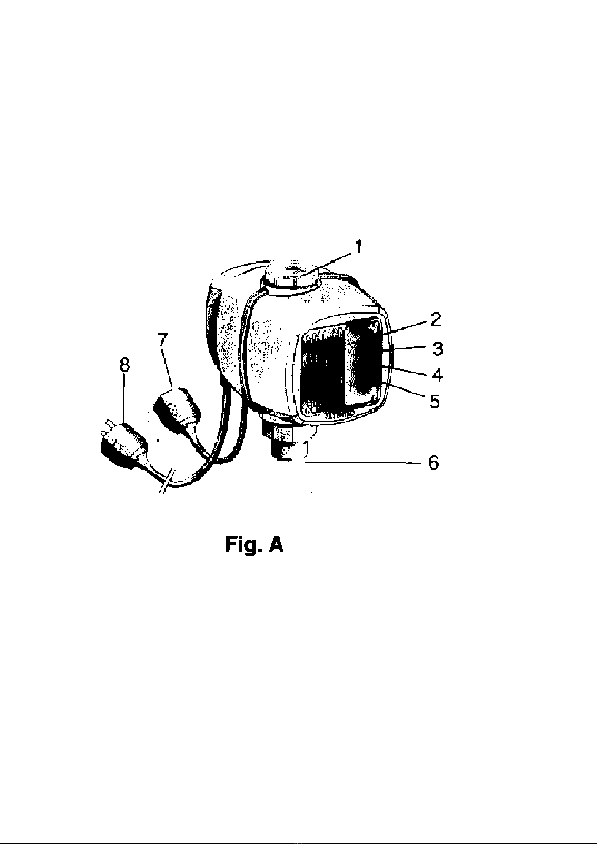
water jet from the inlet side (6)
9. WARRANTY
The warranty is valid for a period of 12 months from the date of purchase solely for
defects in materials or workmanship The warranty does not cover malfunctions due to
misuse or to failure to follow the instructions imparted by the Manufacturer
The warranty will be regarded as null and void if the plug or power cord have been
altered or tampered with (only the modifications mentioned in part 4 of this manual are
allowed) or if the Hydrotronic has been partly or totally disassembled
10. OPERATING PROBLEMS
PROBLEM CAUSE CORRECTIVE ACTION
Red LED (3)
blinks
No water Normal water flow must be restored
Red LED (3) stays
on continuously
No automatic reset attempts
left
Disconnect the power plug and then reconnect it
Pump keeps
starting and
stopping
1 The system is leaky
(unsealed)
2 Foreign materials inside the
Hydrotronic
1 Check the system and the connection with the
pump
2 Disconnect the power plug, remove the
Hydrotronic from the pump and rinse it
thoroughly by spraying water from the inlet side
(6) - i e using a garden hose
Pump dose not
work
1 The pump may be defected
2 The Hydrotronic may be
obstructed by foreign
materials or Limescale
(calcium)
Disconnect the Hydrotronic from the pump, both
hydraulically and electrically Try starting the
pump alone after connecting it to the mains If the
pump operates properly, inspect the Hydrotronic
from outlet hole (1), checking if the inner
impeller rotates freely If friction is encountered
Wash the Hydrotronic by filling it with vinegar or
other anti-scale product through outlet (1) It the
impeller turns freely contact the after-sales
service team

OPERATING INSTRUCTIONS
For further information on operating troubles, carefully read the operating instructions of
the related pump
We expressly state that, In conformity with the legislation in force, no responsibility Is
assumed for damage caused by our products through Improper repairing techniques or
due to the use of non genuine spare parts or of components not approved by LEADER or,
at all events, resulting from repairs not carried out at a LEADER service centre or by
authorized skilled personnel The same applies to attachments and accessories
11. SAFETY AND CONFORMITY MARKS
Automati ally operated pumps are produ ed in omplian e with the safety
regulations in for e and are subje ted to verifi ation by the ompetent agen ies
(TUV and CSA/NRTL).

3226 BENCHMARK DRIVE
LADSON, SC 29456 USA
TEL: 1-843-824-6332
FAX: 1-843-797-3366
Table of contents