Leadshine Technology Co. DM422 User manual

User sManual
For
DM422
FullyDigital SteppingDriver
Version 1.0
2010All RightsReserved
Attention:Pleaseread thismanual carefullybeforeusingthe driver!
The contentinthismanualhasbeencarefullypreparedand isbelievedtobeaccurate,butno
responsibilityisassumedforinaccuracies.
Leadshinereservestherighttomakechangeswithoutfurthernoticetoanyproductshereinto
improvereliability,function ordesign.Leadshinedoesnotassumeanyliabilityarisingoutofthe
applicationoruseofanyproductorcircuitdescribedherein;neitherdoesitconveyanylicense
underitspatentrightsofothers.
Leadshine sgeneralpolicydoesnotrecommend theuseofitsproductsinlifesupportoraircraft
applicationswhereinafailureormalfunctionoftheproductmaydirectlythreatenlifeorinjury.
AccordingtoLeadshine stermsandconditionsofsales,theuserofLeadshine sproductsinlife
supportoraircraftapplicationsassumesall risksofsuchuseandindemnifiesLeadshineagainst all
damages.
2010byLeadshineTechnologyCompanyLimited.
AllRightsReserved

Contents
I
TableofContents
1. Introduction, FeaturesandApplications....................................................................1
Introduction...........................................................................................................1
Features.................................................................................................................1
Applications..........................................................................................................1
2. Specifications............................................................................................................2
ElectricalSpecifications........................................................................................2
MechanicalSpecifications.....................................................................................2
EliminationofHeat...............................................................................................2
OperatingEnvironmentandotherSpecifications..................................................3
3. PinAssignmentandDescription...............................................................................3
ConnectorP1 Configurations................................................................................3
SelectingActivePulseEdgeandControlSignalMode........................................4
ConnectorP2 Configurations................................................................................4
4. ControlSignalConnector(P1)Interface...................................................................4
5. Connecting theMotor................................................................................................5
Connectionsto4-leadMotors...............................................................................5
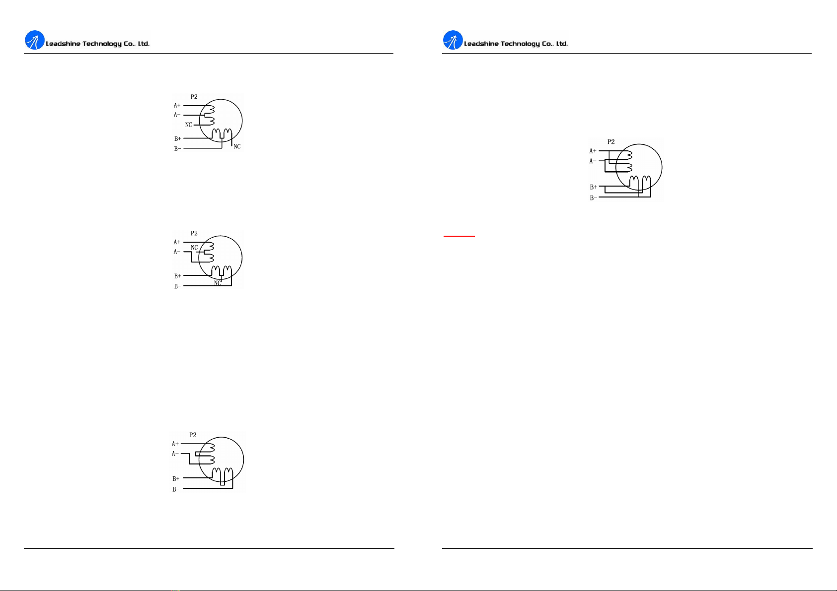
Connectionsto6-leadMotors...............................................................................5
HalfCoil Configurations...............................................................................5
FullCoil Configurations................................................................................6
Connectionsto8-leadMotors...............................................................................6
SeriesConnections........................................................................................6
ParallelConnections......................................................................................7
6. PowerSupplySelection............................................................................................7
RegulatedorUnregulatedPowerSupply..............................................................7
MultipleDrivers....................................................................................................8
SelectingSupplyVoltage.......................................................................................8
7. SelectingMicrostepResolutionand DriverOutputCurrent.....................................8
MicrostepResolutionSelection............................................................................8
CurrentSettings.....................................................................................................9
Contents
II
Dynamiccurrentsetting................................................................................9
Standstill currentsetting..............................................................................10
8. Wiring Notes...........................................................................................................10
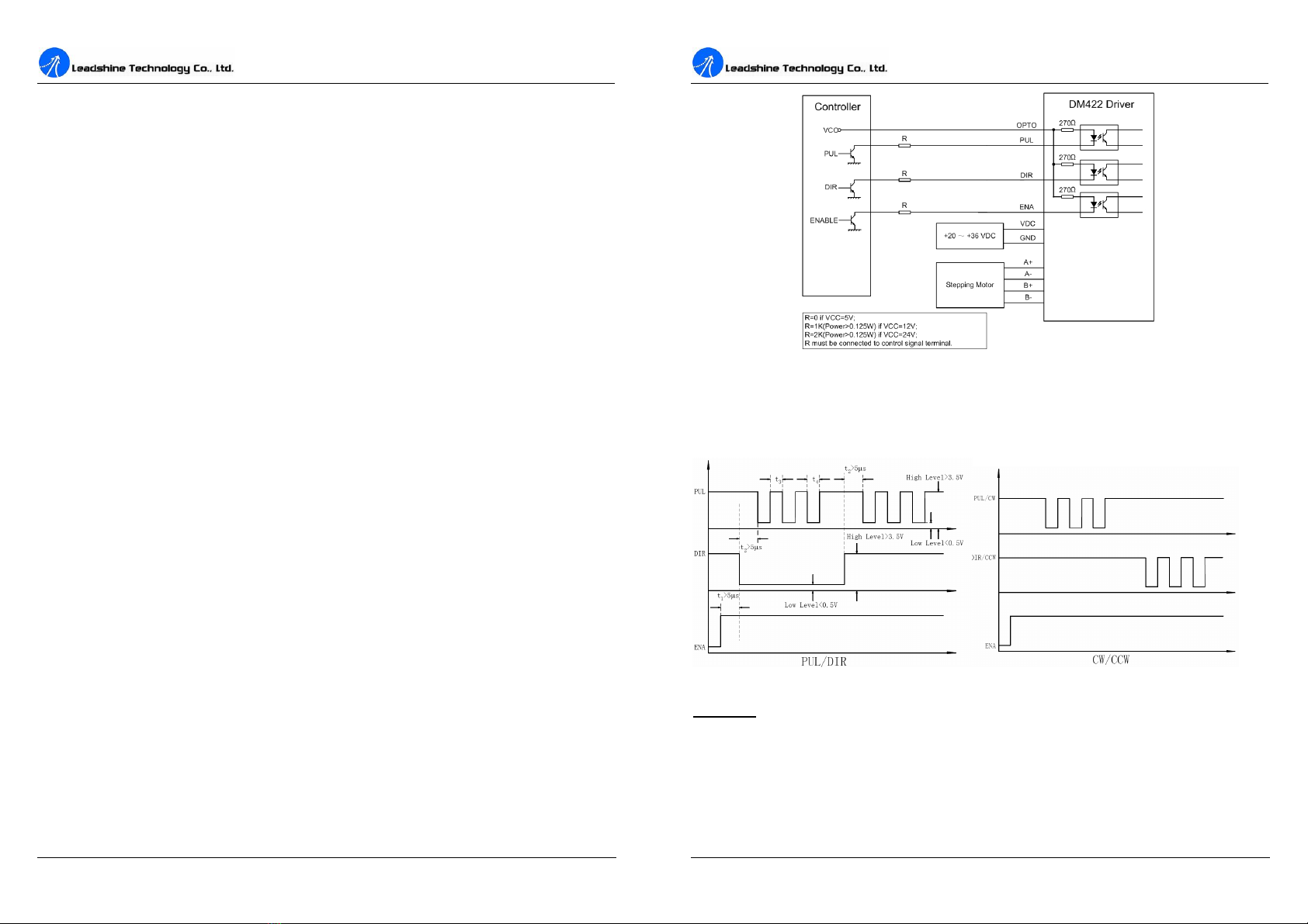
9. TypicalConnection..................................................................................................10
10. Sequence ChartofControlSignals.......................................................................11
11. ProtectionFunctions..............................................................................................12
Over-currentProtection...............................................................................12
Over-voltageProtection..............................................................................12
PhaseErrorProtection.................................................................................12
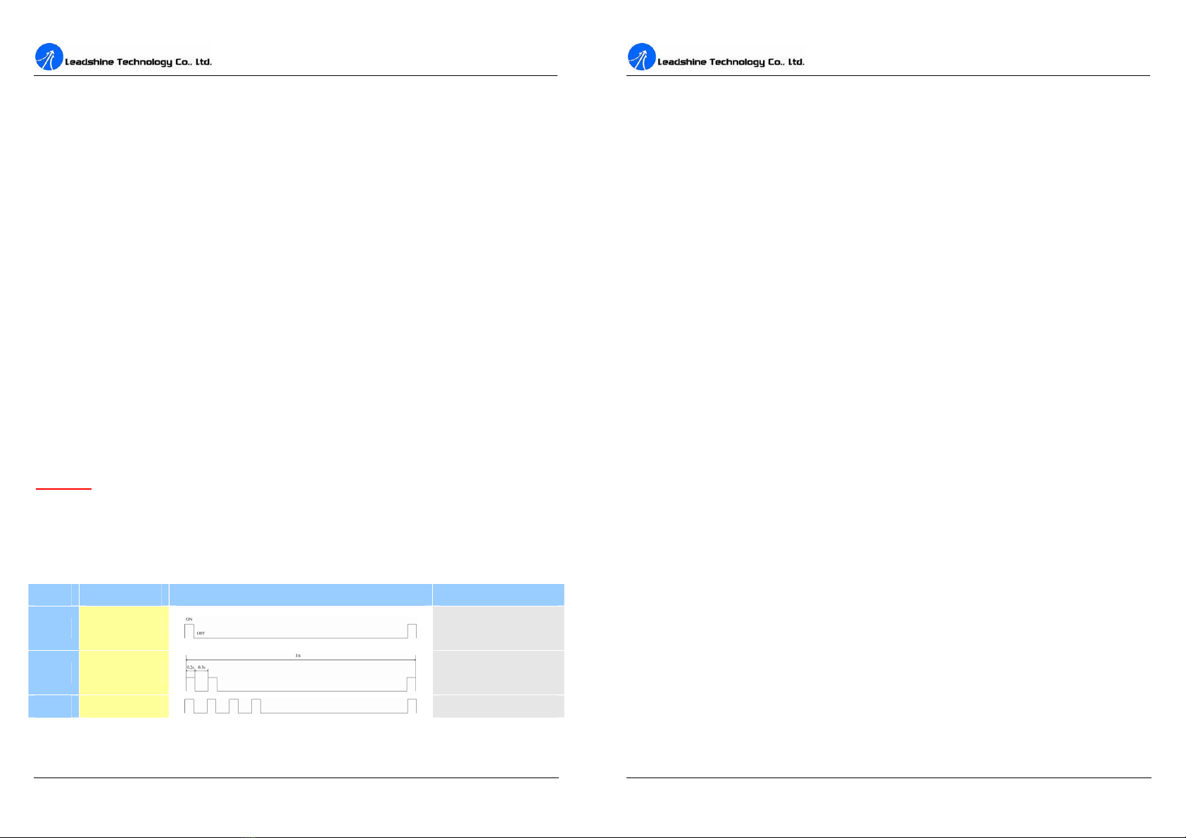
ProtectionIndications..................................................................................12
12. FrequentlyAskedQuestions..................................................................................13
ProblemSymptomsand PossibleCauses............................................................14
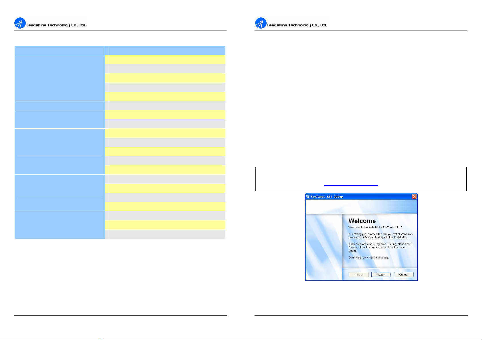
13. ProfessionalTuningSoftwareProTuner................................................................15
Introduction.........................................................................................................15
SoftwareInstallation...........................................................................................15
ConnectionsandTesting.....................................................................................19
RS232 Interface Connection...............................................................................19
TestingtheSteppingSystem...............................................................................19
SoftwareIntroduction..........................................................................................20
ProTunerMain Window..............................................................................20
ProTunerToolbar.........................................................................................20
Option..........................................................................................................21
ComConfig Window..................................................................................21
ParametersConfiguration Window.............................................................21
Tuning.........................................................................................................22
Anti-ResonanceIntroduction......................................................................25
InternalPluser.............................................................................................26
ProcedureforAchieving OptimumPerformance........................................27
Err_check....................................................................................................28
About...........................................................................................................29
APPENDIX.................................................................................................................29

Contents
III
TwelveMonthLimited Warranty........................................................................29
Exclusions...........................................................................................................29
Obtaining WarrantyService................................................................................29
WarrantyLimitations...........................................................................................29
ContactUs...................................................................................................................30
DM422DigitalSteppingDriveManual V1.0
1. Introduction,Featuresand Applications
Introduction
TheDM422isaversatilityfullydigitalsteppingdriverbasedonaDSPwithadvancedcontrol
algorithm.TheDM422isthenextgenerationofdigital steppingmotorcontrols.Itbringsaunique
levelofsystemsmoothness,providingoptimumtorqueandnullsmid-rangeinstability.Motor
self-testandparameterauto-setuptechnologyoffersoptimumresponseswithdifferentmotorsand
easy-to-use.Thedrivenmotorscanrunwithmuchsmallernoise,lowerheating,smoother
movementthanmostofthedriversinthemarkets.ItsuniquefeaturesmaketheDM422anideal
solutionforapplicationsthatrequirelow-speedsmoothness.ComparedtotheDM422C,the
DM422makesthemotorrunintohigherspeedandtheusercanconfigurethestandstill currentin
thesoftware. What smore,apulsefilter(smoother)hasbeenbuilt intotheDM422.
Features
lAnti-Resonance,providesoptimumtorque
and nullsmid-rangeinstability
lMotorself-testandparameterauto-setup
technology,offersoptimumresponseswith
different motors
lMulti-Steppingallowsalowresolutionstep
inputtoproduceahighermicrostepoutput
forsmoothsystemperformance
lMicrostepresolutionsprogrammable,from
full-stepto102,400steps/rev
lSupplyvoltageupto+40VDC
lOutputcurrentprogrammable,from0.3Ato
2.2A
lPulseinputfrequencyup to75 KHz
lTTLcompatibleandopticallyisolatedinput
lAutomaticidle-current reduction
(Reductionratecanbesoftwareconfigured)
lSupportPUL/DIRand CW/CCWmodes
lOver-voltage, over-current,phase-error
protections
Applications
Suitableforawiderangeofsteppingmotors,fromNEMAframesize14to23.Itcanbeusedin
variouskindsofmachines,suchaslasercutters,lasermarkers,highprecisionX-Ytables,labeling
machines,andsoon.ItsuniquefeaturesmaketheDM422anidealsolutionforapplicationsthat
requirelow-speedsmoothness.

DM422DigitalSteppingDriveManual V1.0
2
2. Specifications
ElectricalSpecifications(Tj =25 /77℉)
DM422
Parameters Min Typical Max Unit
Output current 0.3 - 2.2(1.6RMS) A
Supplyvoltage +20 - +40 VDC
Logicsignal current 7 10 16 mA
Pulseinputfrequency 0 - 75 kHz
Isolationresistance 500 MΩ
MechanicalSpecifications( unit: mm [inch] )
Figure 1:Mechanicalspecifications
EliminationofHeat
lDriver sreliableworkingtemperatureshouldbe<70 (158 ),and motorworkingtemperature
shouldbe<80 (176 );
lItisrecommendedtouseautomaticidle-currentmode,namelycurrentautomaticallyreduceto
60%whenmotorstops,soastoreducedriverheatingandmotorheating;
lIt isrecommendedtomountthedriververticallytomaximize heatsinkarea. Useforcedcooling
methodtocool thesystem ifnecessary.
DM422DigitalSteppingDriveManual V1.0
3
Operating EnvironmentandotherSpecifications
Cooling Natural CoolingorForcedcooling
Environment Avoiddust, oil fog andcorrosivegases
AmbientTemperature 0-50 (32 -122 )
Humidity 40%RH-90%RH
OperatingTemperature 70 (158 )Max
OperatingEnvironment
Vibration 5.9m/s2 Max
StorageTemperature -20 -65 (-4 -149 )
Weight Approx. 100g(3.5274oz)
3. PinAssignmentand Description
TheDM422hastwoconnectors,connectorP1forcontrolsignalsconnections,and connectorP2for
powerandmotorconnections.Thefollowingtablesarebriefdescriptionsofthetwoconnectors.
Moredetaileddescriptionsofthepinsandrelatedissuesarepresentedinsection4,5, 9.
ConnectorP1 Configurations
PinFunction Details
PUL
Pulsesignal: Insinglepulse(pulse/direction)mode,thisinputrepresentspulse
signal,eachrisingorfallingedgeactive(softwareconfigurable);4-5Vwhen
PUL-HIGH,0-0.5VwhenPUL-LOW.Indoublepulsemode(pulse/pulse),
thisinputrepresentsclockwise(CW)pulse,activebothathighlevelandlow
level(softwareconfigurable).Forreliableresponse,pulsewidthshouldbe
longerthan7.5μs.Seriesconnectresistorsforcurrent-limitingwhen+12Vor
+24Vused. ThesameasDIRandENAsignals.
DIR
DIRsignal: Insingle-pulsemode,thissignalhaslow/highvoltagelevels,
representingtwodirectionsofmotorrotation;indouble-pulsemode(software
configurable),thissignaliscounter-clock(CCW)pulse,activebothathigh
level andlowlevel(softwareconfigurable).Forreliablemotionresponse,DIR
signalshouldbeaheadofPULsignalby5μsatleast.4-5VwhenDIR-HIGH,
0-0.5VwhenDIR-LOW.Pleasenotethatrotationdirection isalsorelatedto
motor-driverwiringmatch.Exchangingtheconnectionoftwowiresforacoil
tothedriverwill reversemotiondirection.
OPTO Opto-couplerpowersupply,and thetypicalvoltageis+5V.Seriesconnect
resistors(atthePUL,DIR,ENAterminals)forcurrent-limitingwhen+12Vor
+24Vused.
ENA Enablesignal: Thissignalisusedforenabling/disablingdriver.Highlevelfor
enablingthedriverandlowlevelfordisablingthedriver.Usuallyleft
UNCONNECTED(ENABLED).

DM422DigitalSteppingDriveManual V1.0
4
SelectingActivePulseEdgeandControlSignalMode
TheDM422 supportsPUL/DIRand CW/CCWmodesand pulseactiveatrisingorfallingedge.See
moreinformationaboutthesesettingsinSection13.DefaultsettingisPUL/DIRmodeand rising
edgeactive.
ConnectorP2 Configurations
PinFunction Details
+Vdc Powersupply, 20~40VDC,IncludingvoltagefluctuationandEMFvoltage.
GND PowerGround.
A+,A- MotorPhaseA
B+, B- MotorPhaseB
4. ControlSignalConnector(P1)Interface
TheDM422usesopto-couplerstoincreasenoiseimmunityand interfaceflexibility.Ifthe
opto-couplers supplyvoltageishigherthan+5V,acurrent-limitingresistorneedstobeconnected
ateachcommand signalterminaltopreventoverheatingtheopto-couplers.Inthefollowing
figures, connectionstoopen-collectoranddifferential controllerareillustrated.
Figure 2:Connectionstoopen-collectorsignal(common-anode)
DM422DigitalSteppingDriveManual V1.0
5
Figure 3:Connectionstodifferentialcontrolsignal
5. ConnectingtheMotor
TheDM422candriveany2-pahseand 4-pahsehybridsteppingmotors.
Connectionsto 4-leadMotors
4leadmotorsaretheleastflexiblebuteasiesttowire.Speedandtorquewilldepend onwinding
inductance.Insettingthedriveroutputcurrent,multiplythespecifiedphasecurrentby1.4to
determinethepeakoutput current.
Figure 4:4-leadMotorConnections
Connectionsto 6-leadMotors
Like8leadsteppingmotors,6leadmotorshavetwoconfigurationsavailableforhighspeedorhigh
torqueoperation. Thehigherspeedconfiguration,orhalfcoil,issodescribedbecauseit usesonehalf
ofthemotor sinductorwindings.Thehighertorqueconfiguration, orfullcoil,usesthefullwindings
ofthephases.
HalfCoilConfigurations
Aspreviouslystated,thehalfcoilconfigurationuses50%ofthemotorphasewindings.Thisgives
lowerinductance, hence,lowertorqueoutput. Liketheparallel connectionof8leadmotor, thetorque

DM422DigitalSteppingDriveManual V1.0
6
outputwillbemorestableathigherspeeds.Thisconfigurationisalsoreferredtoashalfchopper.In
settingthedriveroutputcurrentmultiplythespecifiedperphase(orunipolar) currentratingby1.4to
determinethepeakoutput current.
Figure 5:6-leadmotorhalfcoil (higherspeed)connections
FullCoilConfigurations
Thefullcoil configurationonasixleadmotorshouldbeusedinapplicationswherehighertorqueat
lowerspeedsisdesired.Thisconfigurationisalsoreferredtoasfullcopper.Infull coil mode,the
motorsshouldberunatonly70%oftheirratedcurrenttopreventoverheating.
Figure 6:6-leadmotorfull coil (highertorque)connections
Connectionsto 8-leadMotors
8leadmotorsofferahighdegreeofflexibilitytothesystemdesignerinthattheymaybeconnected
inseriesorparallel, thussatisfyingawiderangeofapplications.
SeriesConnections
Aseriesmotorconfiguration wouldtypicallybeusedinapplicationswhereahighertorqueatlower
speedsisrequired.Becausethisconfigurationhasthemostinductance,theperformancewillstartto
degradeathigherspeeds.Inseriesmode,themotorsshouldalsoberunat only70%oftheirrated
currenttopreventoverheating.
Figure 7:8-leadmotorseriesconnections
DM422DigitalSteppingDriveManual V1.0
7
ParallelConnections
An8leadmotorinaparallel configurationoffersamorestable, butlowertorqueatlowerspeeds.But
becauseofthelowerinductance,therewill behighertorqueathigherspeeds.Multiplytheperphase
(orunipolar) currentratingby1.96,orthebipolarcurrent ratingby1.4, todeterminethepeakoutput
current.
Figure 8:8-leadmotorparallelconnections
NEVER disconnect orconnectthemotorwhilethepowersource isenergized.
6. PowerSupplySelection
TheDM422canmatchmediumandsmall sizesteppingmotors(fromNEMAframesize14to23)
madebyLeadshineorothermotormanufacturesaroundtheworld.Toachievegooddriving
performances,it isimportanttoselectsupplyvoltageandoutputcurrentproperly.Generallyspeaking,
supplyvoltagedeterminesthehighspeedperformanceofthemotor,whileoutputcurrentdetermines
theoutputtorqueofthedrivenmotor(particularlyatlowerspeed).Highersupplyvoltagewillallow
highermotorspeedtobeachieved,atthepriceofmorenoiseand heating.Ifthemotionspeed
requirementislow,it sbettertouselowersupplyvoltagetodecreasenoise,heatingand improve
reliability.
RegulatedorUnregulatedPowerSupply
Bothregulatedandunregulatedpowersuppliescanbeusedtosupplythedriver.However,
unregulatedpowersuppliesarepreferredduetotheirabilitytowithstandcurrentsurge.Ifregulated
powersupplies(suchasmostswitchingsupplies.)areindeedused,itisimportanttohavelarge
currentoutputratingtoavoidproblemslikecurrentclamp,forexampleusing4Asupplyfor3A
motor-driveroperation. Ontheotherhand,ifunregulatedsupplyisused, onemayuseapowersupply
oflowercurrent ratingthanthatofmotor(typically50%~70%ofmotorcurrent).Thereasonisthat
thedriverdrawscurrentfromthepowersupplycapacitoroftheunregulatedsupplyonlyduringthe
ON duration ofthePWMcycle,butnotduringtheOFFduration.Therefore,theaveragecurrent
withdrawnfrompowersupplyisconsiderablyless thanmotorcurrent.Forexample,two3Amotors
canbewellsuppliedbyonepowersupplyof4Arating.

DM422DigitalSteppingDriveManual V1.0
8
MultipleDrivers
Itisrecommendedtohavemultipledriverstoshareonepowersupplytoreduce cost, ifthesupply
hasenoughcapacity.Toavoidcrossinterference, DONOT daisy-chainthepowersupplyinputpins
ofthedrivers. Instead,pleaseconnectthem topowersupplyseparately.
Selecting Supply Voltage
ThepowerMOSFETsinsidetheDM422canactuallyoperatewithin+20~+40VDC,including
powerinputfluctuationandbackEMFvoltagegeneratedbymotorcoilsduringmotorshaft
deceleration.Highersupplyvoltagecanincreasemotortorqueathigherspeeds,thushelpfulfor
avoidinglosingsteps.However,highervoltagemaycausebiggermotorvibrationatlowerspeed,and
itmayalsocauseover-voltageprotectionorevendriverdamage.Therefore, itissuggestedtochoose
onlysufficientlyhighsupplyvoltageforintendedapplications,and itissuggestedtousepower
supplieswiththeoreticaloutputvoltageof+20 ~+36VDC,leaving roomforpowerfluctuationand
back-EMF.
7. SelectingMicrostepResolutionand DriverOutputCurrent
Microstepresolutionsandoutputcurrentareprogrammable,theformercanbesetfromfull-stepto
102,400steps/revandthelattercanbesetfrom0.3Ato2.2A.See moreinformation about Microstep
and OutputCurrentSetting inSection13.
However,whenit snotinsoftwareconfiguredmode,thisdriverusesa6-bit DIPswitchtoset
microstepresolution,andmotoroperatingcurrent, asshownbelow:
MicrostepResolutionSelection
Whenit snotinsoftwareconfiguredmode,microstepresolutionissetbySW5,6oftheDIPswitch
asshowninthefollowingtable:
DM422DigitalSteppingDriveManual V1.0
9
Microstep Steps/rev.(for1.8 motor) SW5 SW6
1to512 Default/Software configured ON ON
8 1600 OFF ON
16 3200 ON OFF
32 6400 OFF OFF
CurrentSettings
Foragivenmotor,higherdrivercurrentwillmakethemotortooutputmoretorque,butatthesame
timecausesmoreheatinginthemotoranddriver. Therefore, outputcurrentisgenerallysettobesuch
thatthemotorwill notoverheatforlongtimeoperation.Since paralleland serialconnectionsof
motorcoilswill significantlychangeresultinginductanceandresistance,it isthereforeimportantto
setdriveroutputcurrentdependingonmotorphasecurrent,motorleadsand connectionmethods.
Phasecurrentratingsuppliedbymotormanufacturerisimportantinselectingdrivercurrent,however
theselectionalsodependsonleadsand connections.
Whenit snotinsoftwareconfiguredmode,thefirstthreebits(SW1,2, 3)oftheDIPswitchareused
tosetthedynamiccurrent.Selectasettingclosest toyourmotor srequiredcurrent.
Dynamiccurrentsetting
PeakCurrent RMSCurrent SW1 SW2 SW3
Default/Software configured(0.3to2.2A) ON ON ON
0.5A 0.35A OFF ON ON
0.7A 0.50A ON OFF ON
1.0A 0.71A OFF OFF ON
1.3A 0.92A ON ON OFF
1.6A 1.13A OFF ON OFF
1.9A 1.34A ON OFF OFF
2.2A 1.56A OFF OFF OFF
Notes: Duetomotorinductance,theactualcurrentinthecoil maybesmallerthanthedynamic
currentsetting,particularlyunderhighspeedcondition.

DM422DigitalSteppingDriveManual V1.0
10
Standstillcurrentsetting
SW4isusedforthispurpose.OFFmeaningthatthestandstillcurrentissoftwareconfigured,and ON
meaningthatstandstill currentissettobethesameastheselecteddynamiccurrent.
Bydefault,thecurrentautomaticallyreducedto60%oftheselecteddynamiccurrenttwosecond
afterthelastpulse.Theoretically,thiswill reducemotorheatingto36%(duetoP=I2*R)ofthe
originalvalue. ReductionrateandidletimecanbeconfiguredinthePCsoftwareProTuner.See
moreinformationinsection13.
8. WiringNotes
lInordertoimproveanti-interferenceperformanceofthedriver,itisrecommendedtouse
twistedpairshieldcable.
lTopreventnoiseincurredinPUL/DIRsignal,pulse/directionsignalwiresandmotorwires
shouldnotbetieduptogether.Itisbettertoseparatethembyatleast10cm,otherwisethe
disturbingsignalsgeneratedbymotorwilleasilydisturbpulsedirectionsignals,causingmotor
positionerror,system instabilityand otherfailures.
lIf apowersupplyservesseveraldrivers,separatelyconnectingthedriversisrecommended
insteadofdaisy-chaining.
lItisprohibitedtopullandplugconnectorP2whilethedriverispoweredON,becausethereis
highcurrentflowingthroughmotorcoils(evenwhenmotorisatstandstill).Pullingorplugging
connectorP2withpoweronwill causeextremelyhigh back-EMFvoltagesurge,whichmay
damagethedriver.
9.TypicalConnection
Acompletesteppingsystemshouldincludesteppingmotor,steppingdriver,powersupplyand
controller(pulsegenerator).Atypical connection isshownasfigure9.
DM422DigitalSteppingDriveManual V1.0
11
Figure 9:Typicalconnection
10. SequenceChartofControlSignals
Inordertoavoidsomefaultoperationsanddeviations,PUL,DIRandENAshouldabidebysome
rules,shownasfollowingdiagram:
Figure 10:Sequence chartofcontrolsignals
Remark:
a) t1:ENAmustbeaheadofDIRbyatleast5µs.Usually,ENA+and ENA-areNC(not
connected).See “ConnectorP1Configurations”formoreinformation.
b) t2:DIRmustbeaheadofPULeffectiveedgeby5µstoensurecorrect direction;
c) t3:Pulsewidthnotlessthan7.5µs;
d) t4:Lowlevelwidthnotlessthan7.5µs.

DM422DigitalSteppingDriveManual V1.0
12
11. ProtectionFunctions
Toimprovereliability,thedriverincorporatessomebuilt-inprotectionfunctions.TheDM422uses
oneREDLEDtoindicatewhatprotectionhasbeenactivated.TheperiodictimeofREDis3s
(seconds),and howmanytimestheREDturnsonindicateswhatprotectionhasbeenactivated.
BecauseonlyoneprotectioncanbedisplayedbyREDLED,sothedriverwill decidewhaterrorto
displayaccordingtotheirpriorities.Seethefollowing ProtectionIndications tablefordisplaying
priorities.
Over-currentProtection
Over-currentprotection willbeactivatedwhencontinuouscurrentexceedsthelimitorincaseof
shortcircuit betweenmotorcoilsorbetweenmotorcoilandground, andREDLEDwillturnon once
withineachperiodictime(3s).
Over-voltageProtection
Whenpowersupplyvoltageexceeds48±2VDC,protection will beactivatedandREDLEDwill
turnontwice withineachperiodictime(3s).
PhaseErrorProtection
Motorpowerlineswrong¬connectedwill activatethisprotection.REDLEDwill turnon four
timeswithineachperiodictime(3s).
Attention: Whenaboveprotectionsareactive,themotorshaftwill befreeortheLEDwill turnred.
Resetthedriverbyrepoweringit tomakeitfunctionproperlyafterremovingaboveproblems.Since
thereisnoprotection againstpowerleads(﹢,﹣)reversal, itiscriticaltomakesurethatpower
supplyleadscorrectlyconnectedtodriver.Otherwise,thedriverwill bedamagedinstantly.
ProtectionIndications
Priority
Time(s)ofON Sequence wave ofREDLED Description
1st 1 Over-currentprotection
2nd 2
Over-voltageprotection
3rd 4 Phase errorprotection
DM422DigitalSteppingDriveManual V1.0
13
12. FrequentlyAskedQuestions
Intheeventthatyourdriverdoesn toperateproperly, thefirst stepistoidentifywhethertheproblem
iselectricalormechanicalinnature. Thenextstepistoisolatethesystemcomponentthatiscausing
theproblem. Aspart ofthisprocess youmayhavetodisconnecttheindividual componentsthatmake
up yoursystemandverifythattheyoperateindependently.Itisimportanttodocumenteachstepin
thetroubleshootingprocess.Youmayneedthisdocumentationtoreferbacktoatalaterdate,and
thesedetailswill greatlyassistourTechnicalSupportstaffindeterminingtheproblemshouldyou
needassistance.
Manyoftheproblemsthataffectmotioncontrolsystemscanbetracedtoelectricalnoise,controller
softwareerrors, ormistakeinwiring.

DM422DigitalSteppingDriveManual V1.0
14
ProblemSymptomsand PossibleCauses
Symptoms PossibleProblems
Nopower
Microstepresolutionsettingiswrong
DIPswitchcurrentsettingiswrong
Fault condition exists
Motorisnotrotating
Thedriverisdisabled
Motorrotatesinthewrongdirection
Motorphasesmaybeconnectedinreverse
DIPswitchcurrentsettingiswrong
Thedriverinfault Somethingwrongwithmotorcoil
Control signal istoo weak
Control signal isinterfered
Wrongmotorconnection
Somethingwrongwithmotorcoil
Erraticmotormotion
Current settingistoo small, losingsteps
Current settingistoo small
Motorisundersizedfortheapplication
Accelerationissettoo high
Motorstallsduringacceleration
Powersupplyvoltagetoo low
Inadequateheatsinking/cooling
Automaticcurrentreductionfunction not beingutilized
Excessivemotorand driverheating
Current issettoo high
DM422DigitalSteppingDriveManual V1.0
15
13. ProfessionalTuningSoftwareProTuner
Introduction
Thissectionwillprovideanoverviewofconnectionand basicsetup instructionsforLeadshine s
digitalsteppingdriverDM422usingthe ProTuner software.Theseinstructionswill walkyouthrough
thefollowingstepsnecessarytostart up yourdriverandmotor. Thissectionisintendedforsettingup
thedriverwiththe ProTuner.
SoftwareInstallation
The ProTuner iswindowsbasedsetupsoftwarefortuningLeadshine sdigitalstepperdriverDM422.
Itcanruninwindowssystems,includingWin95/Win98/WindowsNT/Windows2000/WindowsXP.
And theselectedPCshouldhave1serialportat leastforcommunicatingwiththedriver.
Doubleclick “ProTuner_DM422_Setup_V2.0.exe”tobegininstallingthe ProTuner.SeeFigure11.
Click Next toenterthe “LicenseAgreement”window. SeeFigure12.
Figure 11:Begintoinstall the ProTuner
Note: TheusercangetthesoftwarefromeitherLeadshineCDorwebsite.Please
getthelatestversionfrom http://www.leadshine.com.

DM422DigitalSteppingDriveManual V1.0
16
Figure 12:License agreement
Choose “Iagree tothetermsofthislicenseagreement”andclick Next tocontinueinstallation.The
usercanenteruser sinformationinthefollowingwindow.SeeFigure13.Afterenteringtheuser s
information, click Next toselectinstallationfolder,whereyouwouldliketoinstall the ProTuner.See
Figure14.
Figure 13:User sinformationsettings
DM422DigitalSteppingDriveManual V1.0
17
Figure 14:Installation foldersettings
Figure 15:Shortcutfoldersetting
Setthe “ShortcutFolder”inFigure15andcontinuetoinstallthe ProTuner byfollowingFigure16
andFigure17.An InstallationSuccessful windowwillappearifthe ProTuner isinstalled
successfully. SeeFigure18.

DM422DigitalSteppingDriveManual V1.0
18
Figure 16:Installation informationsummarization
Figure 17:Installing the ProTuner
DM422DigitalSteppingDriveManual V1.0
19
Figure 18:Finishinstallation
ConnectionsandTesting
ConnectthesteppingsystemaccordingtothecontentsinprevioussectionsandconnectthePCtothe
driverasthefollowingfigure.
RS232 InterfaceConnection
Figure 19:RS232interface connection
Testing theStepping System
Turnonthepowersupply,thegreen(Power)LEDwilllight.TheDM422 hasdefaultparameters
storedinthedriver.Ifthesystemhasnohardwareandwiringsproblem,themotorshouldbelocked
and thedrivershouldbeready.
If theredLEDimmediatelyturnson (flickers),thencheckpowersupply,themotor,motorwirings
DM422

DM422DigitalSteppingDriveManual V1.0
20
and tryagain.Openthetuningsoftware ProTuner andcheckdriverstatusbyclicking Err_check.If
it s PhaseError,checkthemotor,motorwiringsandtryagain.Ifitstill doesn tworkafteryou
followedall oftheprevioussteps,pleasecontactusat info@elindar.com.ar.
If theREDLEDisOFFandthemotorisnormal,thenyoucanstarttotunetheservo with ProTuner.
However, werecommend youseethefollowingcontentsbeforestartingtuning.
SoftwareIntroduction
ProTuner MainWindow
Figure 20:ProTuner
ProTuner Toolbar
MenuBar
StatusBar
ComConfiguration
CurrentLoopTuning
ParametersConfiguration
SystemConfigure
ErrorCheck
Contact Information
Product Information
Exit
DM422DigitalSteppingDriveManual V1.0
21
Option
Theusercanchoosethreedrop-downmenusbyclicking “Option”,including ComConfiguration,
ParametersConfiguration,and Exit.
lComConfiguration:ConfigureComcommunicationinterface.
lParameteresConfiguration: Read/writeparametersbetweenthedriverandtheProTuner,or
saveconfigurationasafileandloadconfigurationfromafile.
lExit: Exit the ProTuner.
ComConfigWindow
Figure 21:RS232communication configurationwindow
Serial Port: Selecttheserial communicationporttowhichthedriverisconnected. Thefactorydefault
settingisCOM1.
BaudRate: Selectthecommunication baudrate. Thefactorydefaultsettingis38400.
Click Open buttontoestablishaconnectionwiththespecifiedsettings.Whenconnecting,youcan
readstoredparametersettingfromthedrivertotheProTuner,orwritenewparametersettingfromthe
ProTunertothedriversettingsinthe parametersconfiguration window.
ParametersConfigurationWindow
Recommend toalwayskeepthiswindowactive.Inthiswindow,theusercanreadtheparameter
settingfromthedriver,orwriteparameterssettingtothedriverafterfinishingtoconfigureallthe
settings.Inaddition,theusercanalsosavetheconfigurationtoafileforlateruseorloada
configurationfromastoredfile.Seefigure22.

DM422DigitalSteppingDriveManual V1.0
22
ReadRAM: Readparametersettingsfrom thedriver sRAMtotheProTuner.
WriteRAM: WriteparametersettingsfromtheProTuenrtothedriver sRAM.
WriteEEprom: WriteparametersettingsfromtheProTuenrtothedriver sEEprom.
ResetDriver: Resetall parametertodefault value.
Figure 22:Parametersconfiguration window
Tuning
Theusercanchooseoneortwodrop-downmenu(s)byclicking Tuning,including CurrentLoop and
SystemConfig.
lCurrentLoop:InCurrentTuningwindow,theusercantunethe Kp (ProportionalGain)and
Ki (IntegralGain) ofdriver scurrentlooptooptimizeresponseswithdifferentmotors.
Start/RestartaStepResponsetesttogetanoptimum response.
Kp:ProportionalGain.ProportionalGaindeterminestheresponseofthedrivertocurrentsetting
command.LowProportionalGainprovidesastablesystem(doesn toscillate),haslowstiffness,and
largecurrenterror,causingpoorperformancesintrackingcurrentsettingcommand ineachsteplike
Figure23.Too largeProportionalGainvalueswill causeoscillationsandunstablesystems.
Loadconfigurationsfromafile
Saveconfigurationtoafile
Closethiswindow.
DM422DigitalSteppingDriveManual V1.0
23
Figure 23:CurrentTuningwindow
Ki: IntegralGain.IntegralGainhelpsthedrivertoovercomestaticcurrenterrors.Aloworzero
valuefortheIntegralGainmayhavecurrenterrorsatrest. IncreasingtheIntegralGaincanreducethe
error. IftheIntegralGainistoo large,thesystemsmay “hunt”(oscillate)about thedesiredposition.
Start button:TheusercanstartaStepResponsetestbyclickingthisbutton.Start/RestartaStep
ResponsetesttogetanoptimumresponselikeFigure23,andremembertosavethesettingstothe
driverbyclicking WriteEEprom in parametersconfiguration windowwhenfinishtuning.
Auto button:Clickthisbutton toauto-configureKpandKifortheconnectedmotor.Ithasthesame
effect aschangingSW4twotimesinonesecond.
Figure 24:Kp=356, Ki=15 (poorperformances)

DM422DigitalSteppingDriveManual V1.0
24
Notes:
However,iftheuserdoesnotwanttotunethecurrentloopafterchangingadifferentsteppingmotor,
then Motorself-testand parameter auto-setup technologyoftheDM422canreplacemanualtuning
thedriverwith ProTuner.JustchangesSW4twotimesin1second(withoutProTuner),orclick Auto
button,andthenthedriverwillauto-identifythenewmotorand auto-configurerelatedcontrol
parametersforoptimum responses. Recommend usethisfunctionafterchangingthedrivenmotor.
lSystemConfig:
In SystemConfig window,theusercanconfigurePeakCurrent,Microstep,ElecDamp,IdleCurrent,
IdleTime,CommandType,ActiveEdgeandeliminatemotorresonance.Abuilt-inpulsegenerator
canbeusedfortest duringtuning.SeePicture25.
Figure 25:SystemConfigure Window
DM422DigitalSteppingDriveManual V1.0
25
PeakCur: PeakCurrent.Thevalueisthepeakcurrent totheselectedmotorandcanbesetfrom0.1
to2.2A.Theusercansetthepeakcurrentwith ProTuner orDIPswitches,seemoreinformation
aboutsettingoutputcurrentofthedriverinsection5 “ConnectingtheMotor”andsection7
“SelectingMicrostepResolutionandDriverOutputCurrent”.
MicroStep: MicrostepResolution.Thevalueisdriver smicrostepresolutionsettingandcanbeset
from1to512.Theusercansetthemicrostepwith ProTuner orDIPswitches,Seemoreinformation
aboutsettingoutputcurrentofthedriverinsection7 “SelectingMicrostepResolutionand Driver
OutputCurrent”.
ElecDamp:ElectronicDampingCoefficient.Theelectronicdampingrestrainresonanceofthe
systemand preventamplitudeoftheoscillationfromincreasingtotheextendthatit makesthemotor
out ofcontrol. Theoptimalvaluedependsonthesystem, andthedefaultvalueis3000.
IdleCurrent: StandstillCurrentwhenmotorstop. When themotorstop timeexceedsthe Idle
Time,themotorcoilcurrentreducestoIdleCurrent(Inpercentage).Thepercentageisratedtothe
PeakCurrent.
IdleTime:See IdleCurrent.
PulseFilterEnable:ClickthecheckboxwillturnontheinternalpulsesmootherorfilterofDM422.
DirectionDef:DirectionDefinition. Relatethedefaultrunningdirectionto aHIGH levelinputin
DIRor Low level inputinDIR.ThispanelisusedforPUL/DIRcommand typeonly.Pleasenotethat
thedefaultdirectionisalsorelatedtomotorcoil connections.
CommandType:Command Type ofcontrolsignal,includingPUL/DIRand CW/CCW.Setthis
parameteraccordingto Command Type ofmotioncontroller.
ActiveEdge:ActiveEdge. Theusercansetthetriggerededgeofpulsecommand signal inthispanel.
WhenthedriverworksinCW/CCWmode,nomatterwhatlevelisatfixedlevelterminal,thedriver
canworksproperly.
Anti-ResonanceIntroduction
Stepmotorsarehighlyresonant, whichresultsinvibrationandringing.Theringingutilizesalarge

DM422DigitalSteppingDriveManual V1.0
26
fractionofthemotor'savailabletorque –therebywastingperformance.Furthermore,atmid-range
velocities,theresonance canbecomesoseverethatthemotorloosessynchronizationandstalls.The
DM422 driverprovidesrobustanti-resonancecontrol tostopthevibrationsand maintainequilibrium.
Thisfeaturerequiresthat thedriverbeconfiguredwithrespect tothetotal inertiainthesystem.Ifset
improperly, theeffectivenessofthefeaturemaybediminished.
Theusercaninvokeordisablethefeaturebysetting Amp and Phase valuesin SystemConfig
window. Amp and Phase valuesall zeroistodisablethefeature,otherwiseistoinvokethefeature.It
shouldbeenabledunlessthesystemconfigurationeitherdoesnotneeditorcannottolerateit.A
systemwithloosecouplingsorviscousloadinggenerallydoesnotneedthisfeature.Ifasystemhas
compliant(springy)couplingandisabsentappreciablyviscosity,itmaynotrespondwelltotheactive,
anti-resonantloopinthedrive.Theanti-resonantfeatureisnotdesignedtodampsucha4th order
system. Iftheapplication ofanti-resonanceresultsindegradationorinstability, it shouldbedisabled.
1
st ResonanceArea:Parametersfor1st resonancearea. It isusuallybetween0.6rpsand1.2rps.
Amp1 isAmplitudeadjustmentfor1st resonance area.
Phase1 isPhaseadjustmentfor1st resonancearea.Theusercanenteravaluedirectlyinthetextbox
ormovethesliderbarbackandforthtogetanoptimumvalue.
2
nd ResonanceArea:Parametersfor2nd resonance area. Itisusuallybetween1.2rpsand2.4rps.
Default Amp2 and Phase2 valuesarezero.
3rd ResonanceArea:Parametersfor3rd resonancearea. Itisusuallybetween2.4rpsand4.8rps.
Default Amp3 and Phase3 valuesare128.
InternalPluser(PulseGenerator)
Theinternalpulsegeneratoroffersasimplemotioncontrolforself-testandanti-resonancetuning.The
usercanadjustmovingvelocity, configurethedirection andrepeatsofthemotion.
Bidirectional:Clickthecheckboxtomakethemotionbebidirectional.Otherwisethemotoronlyrun
inonedirection.
Positive:It isusedtochangetheinitialdirectionforthemotion.
DM422DigitalSteppingDriveManual V1.0
27
Interval:Stoptimebeforethenextmotionrepeat.Unit:ms.
Repeats:Motionrepeattimes. Ifitisbidirectional, onerepeatismovingforwardthenback.
Distance:Movingdistanceinonedirectioninrevolution.
Start/Stop:Start/Stopthemotion.
Note:
Whenyouadjustthevelocitybymovingthesliderforthandback,themotorvelocitywouldnot
changeimmediatelyasyouexpected.Thatisbecausethedriveronlyreadthenewspeedwhenit
changesdirection.Alsobecarefulabouttheinitialdirectionandmovingdistance ifthemotoris
installedonamachine.It isrecommendedthatset lowspeedandsmalldistance ifyouarenotsure
whetherthedirectionanddistanceiscorrectornot.
ProcedureforAchievingOptimumPerformance
Step1: Startthemotiontestbyclicking Start/Stop button.Findaresonancespeedbyslightlymoving
thesliderbarofinternal pulsegeneratorbackandforth.Youcanalsousethearrowkeystoadjust the
speedprecisely.
Step2: Run themotorattheresonance speedand verifythemotorsmoothness.Youmayfindabetter
smoothingvaluebyslightlymovingthesliderbarsof AMP(s)and Phase(s)backandforth.
Itisveryimportanttomakethe AMP(s)and Phase(s)adjustmentsatthepropertestspeedswithan
unloadedmotor.Runningatanincorrecttestspeedwillnotexcitethemotoratitspeakresonance,
makingit moredifficult tofindproperadjustment values. Optimum AMP(s)and Phase(s)valuesmay
bealittledifferentbetweenrunningthetestswithanunloadedmotorandaloadmotor.
Forexample,wefind aresonancespeedat0.98 rps.We begintomovetheAmp1 sliderforthandthe
motorvibrationandnoisebecamelowerandlower.Finallywefindthemoveisthesmoothestwhen
Amp1 is3300.Themotorvibrationandnoiseincreaseif Amp1 exceeds3300.Thenwefollowthe
sameproceduretosearchthebestpoint for Phase1.SeeFigure26. Anti-resonance tuningisdone.
Pleaseremembertoclick WriteEEprom towritethefinalparametersettingstothedriverwhen
finishtuning.

DM422DigitalSteppingDriveManual V1.0
28
Figure 26:1st Anti -Resonance Tuning(Speed=0.98rps)
Err_check
lErrorCheck:Thiswindowshowsboththepresentstatusofeacherroreventandtheirhistory.
Currenterrorevent(s)canberesetbyclicking EraseCurrentErr! button,andallerrorevents
canberesetbyclicking EraseAll! button.Listofthelasttendrivefaults.#0beingthemost
recent, #9istheoldest.SeeFigure27.
Figure 27:Errorcheckwindow
DM422DigitalSteppingDriveManual V1.0
29
OverCurrent: Over-currentProtection.Protection willbeactivatedwhencontinuouscurrent
exceeds16A.
OverVoltage:Over-voltageProtection.Whenpowersupplyvoltageexceeds42±1VDC,protection
willbeactivated.
PhaseErr: PhaseErrorProtection.Motorpowerlineswrong¬connectedwillactivatethis
protection.
ErrCounter: Displayscurrenterror(s)andcurrenterrorhistory.
EraseCurrentErr!:EraseCurrentErr button.Theusercanclearcurrenterror(s)byclickingthis
button.
EraseAll!: EraseAll! button.Theusercanclearallerror(s)includingerrorhistorybyclickingthis
button.
About
Theusercanchoosetwodrop-downmenusbyclicking “About”,including ProductInformation and
lProductInformation window:Showssomeproduct information about ProTuner.

DM422DigitalSteppingDriveManual V1.0
29
APPENDIX
TwelveMonthLimitedWarranty
LeadshineTechnologyCo., Ltd.warrantsitsproductsagainstdefectsinmaterialsand
workmanshipforaperiodof12monthsfromshipment outoffactory.Duringthewarrantyperiod,
Leadshinewilleither,atitsoption,repairorreplaceproductswhichprovedtobedefective.
Exclusions
Theabovewarrantydoesnotextendtoanyproduct damagedbyreasonsofimproperorinadequate
handlingsbycustomer,improperorinadequatecustomerwirings,unauthorizedmodificationor
misuse,oroperationbeyond theelectricalspecificationsoftheproductand/oroperationbeyond
environmentalspecificationsfortheproduct.
ObtainingWarranty Service
Toobtainwarrantyservice,areturnedmaterialauthorizationnumber(RMA)mustbeobtained
fromcustomerserviceate-mail: info@elindar.com.ar beforereturningproductforservice.
CustomershallprepayshippingchargesforproductsreturnedtoLeadshineforwarrantyservice,
and Leadshineshallpayforreturnofproductstocustomer.
Warranty Limitations
Leadshinemakesnootherwarranty,eitherexpressedorimplied,withrespecttotheproduct.
Leadshinespecificallydisclaimstheimpliedwarrantiesofmerchantabilityand fitnessfora
particularpurpose.Somejurisdictionsdonotallowlimitationsonhowlongandimpliedwarranty
lasts,sotheabovelimitationorexclusionmaynot applytoyou. However, anyimpliedwarrantyof
merchantabilityorfitnessislimitedtothe12-monthdurationofthiswrittenwarranty.
Shipping FailedProduct
If yourproductfailduringthewarrantyperiod,e-mailcustomerserviceat info@elindar.com.ar to
obtainareturnedmaterialauthorizationnumber(RMA)beforereturningproductforservice.
Pleaseincludeawrittendescriptionoftheproblemalongwithcontactnameandaddress.Send
failedproducttodistributorinyourarea
DM422DigitalSteppingDriveManual V1.0
30
ContactUs
ChinaHeadquarters
Address: 3/F,Block2,NanyouTiananIndustrialPark,Nanshan District Shenzhen, China
Web: http://www.leadshine.com
SalesHotLine:
Tel: 54 11 4247 4094
54-11-4139-4810
54-11-4139-4827
Web: http://www.elindar.com.ar
Email: leadshine@elindar.com.ar.
.
Table of contents
Other Leadshine Technology Co. DC Drive manuals
Popular DC Drive manuals by other brands

Rockwell Automation
Rockwell Automation Allen-Bradley PowerFlex 750 TotalFORCE Control... Product information

TECHTOP
TECHTOP Topdrive350 Series Quick start up guide

MAIMAN ELECTRONICS
MAIMAN ELECTRONICS SF6015 user manual

Renishaw
Renishaw Equator 500 installation guide

EACON
EACON EC6000 Series quick guide

ABB
ABB ACS580-01 Series Supplement

Dorner
Dorner 2100 Series Installation, maintenance & parts manual

Moeller
Moeller DF5 series Hardware and engineering

ABB
ABB ACS850 series manual

Danfoss
Danfoss VLT AQUA Drive FC 202 instruction manual

YASKAWA
YASKAWA PROFINET V1000 Basic user's guide

BECKER-Antriebe
BECKER-Antriebe E15 Assembly and operating instructions