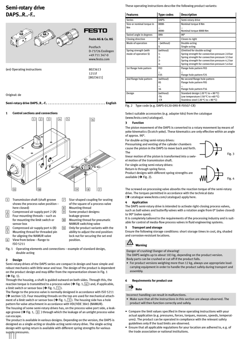
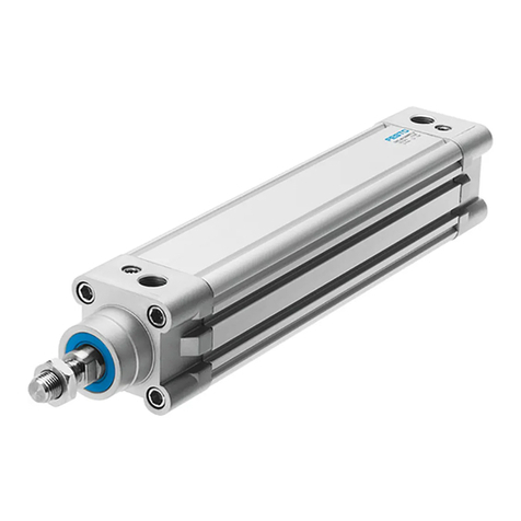
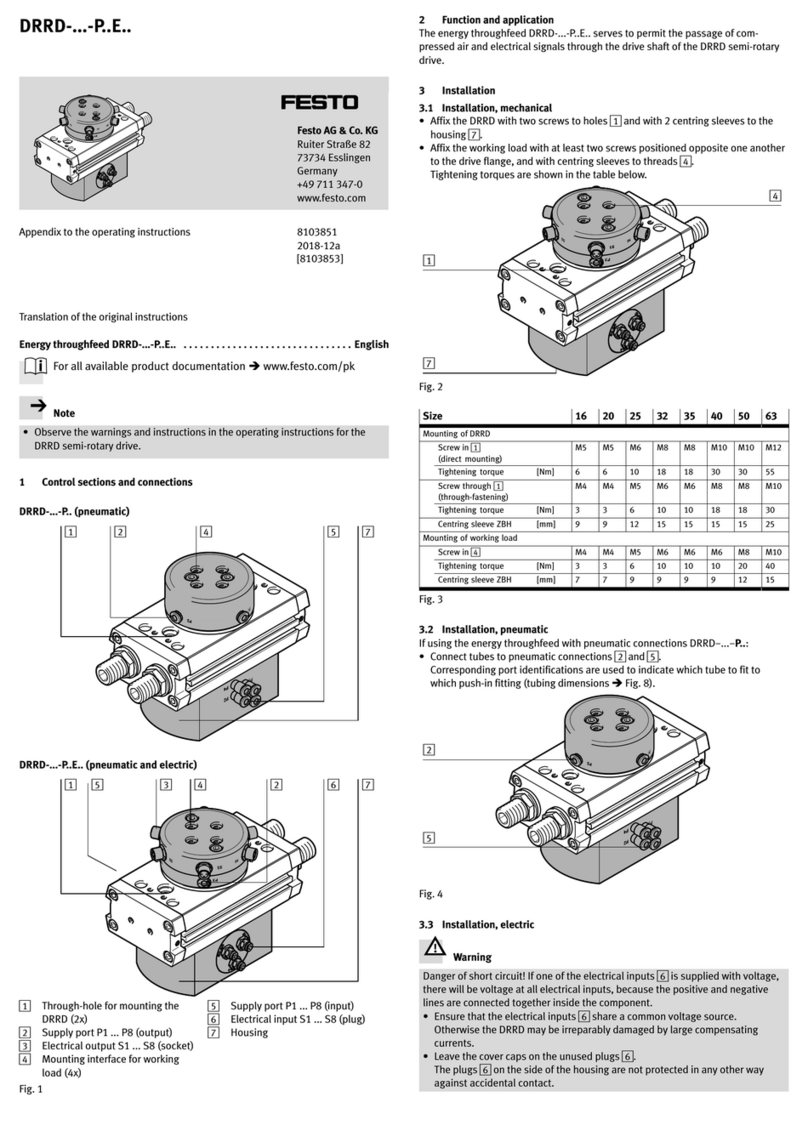
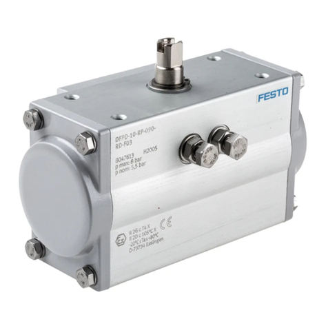
manuals.online logo
Brands
  1. Home
  2. •
  3. Brands
  4. •
  5. Festo
  6. •
  7. DC Drive
  8. •
  9. Festo SLG-8 Series User manual

Festo SLG-8 Series User manual

(en) Operating
instructions
Linear drive
SLG-...
8074727
2017-10e
[8074729]
US Patent No. 6,186,049; 6,196,110; 6,338,294
SLG-...
Festo SLG-... 2017-10e
2
Original instructions
Symbols: Installation and commissioning may only be per
formed in accordance with these instructions by
technicians with appropriate qualifications.
Warning
Caution
Note
Environment
Accessories
English 3.........................................................................
SLG-...
Festo SLG-... 2017-10e English 3
Linear drive SLG-...English
Documentation on the product
For all available product documentation èwww.festo.com/pk
1 Operating parts and connections
1
2
3
4
5
67 8
9
aJ
1Groove for fastening the proximity switch
2Threaded holes for the compressed air connection (alternative connections are
sealed with threaded pins)
3Accurate adjustment of the stop
4Locking screws for rough adjustment of the stop
5Through holes for fastening the drive directly
6End position cushioning (either ...-P or with YSRG-...)
7Lubricating nipple
8Centring holes
9Threaded holes for fastening the work load
aJ Mounting aids geometry (not intended for further use)
Fig. 1
SLG-...
Festo SLG-... 2017-10e English
4
2 Function and application
By applying compressed air to the connec
tions alternately, the inner slide moves back
wards and forwards in the cylinder barrel.
By means of a fixed connection, the outer
slide also moves. A band system seals the
required slot in the cylinder barrel.
The component is designed for space-saving
mass transport only in slide mode.
The pressureless movement of the slide is
only permitted for rectifying faults and at low
speed.
If the speed is too high, the resulting low
pressure can pull the sealing band into the
piston chamber. This can lead to:
– excessive leakage and
– non-permitted accelerations (e.g. if fitted in a vertical position).
3 Conditions of use
Please note
Incorrect handling can lead to malfunctioning.
SMake sure that the points mentioned in this chapter are always observed.
The product will then function correctly and reliably.
SCompare the limits in these operating instructions with your current applica
tion (e.g. pressures, forces, torques, masses, temperatures, speeds).
Only when the load limits are observed can the component function in accord
ance with the relevant safety guidelines.
SConsider the ambient conditions at the location.
ÓÓ
ÓÓ
ÓÓÓ
ÓÓÓ
Fig. 2
Fig. 3: Slide mode
Fig. 4: Yoke mode
SLG-...
Festo SLG-... 2017-10e English 5
SPlease observe the regulations applicable to your location (e.g. local or
national authorities).
SRemove all packaging.
The packing material can be recycled (except for oiled paper = waste).
SEnsure that there is a supply of compressed air which is:
– correctly prepared,
– dried,
– non-lubricated.
Only if non-lubricated air is maintained, will lubrication be guaranteed for the
complete service life of the product.
SSlowly pressurize the complete system.
Movements of the actuators will then be under control, even in unintentional
situations.
SUse the product in its original condition without undertaking any modifica
tions.
4 Transport and storage
SAlways store the component in a lying or
vertical standing position.
Otherwise the component will become
distorted especially with long strokes.
ÓÓÓ
ÓÓÓ
ÓÓ
Fig. 5
SLG-...
Festo SLG-... 2017-10e English
6
5 Fitting
Mechanical fitting
SPrevent the sealing band from being
pressed or sucked in.
Damage to the sealing band reduces the
operating reliability.
A sudden jerk movement of the pressure
less slide can create a low pressure which sucks the sealing band into the
piston chamber.
SPlace the component in position with re
gard to the following points:
– You must be able to gain access to the
operating parts and connections later
when the component is installed.
– The fitting position takes into account
the minimum distances required for
reliable operation of the proximity
switches used.
L1L2= L3L4L5
(SME-10-...) (SMT-10-...)
L1L5
SLG-8-... as desired 10 mm 17 mm 4 mm
SLG-12-... 12 mm as desired
SLG-18-... 46 mm 26 mm
Fig. 8
If the minimum distances are not observed, an individual functional check may
be necessary.
Fig. 6
Fig. 7
SLG-...
Festo SLG-... 2017-10e English 7
SFasten the component as in Fig. 9.
Component supported
Points
Minimum distance: every 100 mm
Surface
Minimum evenness
ÓÓÓÓÓÓÓÓÓ
Fig. 9
If the minimum distances are not observed,
an individual functional check may be necess
ary.
SPlace the work load on the slide as fol
lows:
– The tilting torque of force F parallel to
the cylinder axis and distance a should
remain as small as possible.
– Mass moments of interia occurring in a
dynamic application should be calcu
lated, especially with changing loads.
SSelect the screw for fastening the work
load with maximum screwing depth as in
Fig. 11 / Fig. 12.
j8 12 18
L64 mm 5 mm 8 mm
j1M4 M4 M5
Fig. 12
Fig. 10
ÓÓ
ÓÓ
Ó
Ó
ÎÎ
ÎÎ
Fig. 11
SLG-...
Festo SLG-... 2017-10e English
8
Pneumatic fitting
To set the slide speed:
SUse one-way flow control valves of type GRLA-...
These valves control the exhaust directly
in the compressed air connections.
For screwing in directly without one-way flow
control valves:
SUse barbed fittings or screw connections
with small width across flats.
Fittings with large width across flats re
quire too much space for rubing.
SCheck whether non-return valves with
triggering type HGL-... are required.
If there is a loss of pressure in cases
where the cylinder is fitted in a vertical
position, non-return valves ensure that
the mass remains in the position reached.
SSelect the compressed air connections for
your application:
There are alternative compressed air con
nections (B) to the connections intended
for use (A) when supplied from the fac
tory.
These are sealed with threaded pins.
On the alternative connections, the
threaded pins will only seal when new
sealing medium is applied.
SConnect the SLG-... to the compressed air
connections 2.
The assignment of the connecting holes to
the direction of travel of the slide is shown
in Fig. 16.
Fig. 13
Fig. 14
Fig. 15
(A)
(B)
Fig. 16
SLG-...
Festo SLG-... 2017-10e English 9
Electrical fitting
When using proximity switches:
Please note
SMake sure that the minimum distances from other proximity switches corre
spond to the values specified in the diagram.
In this way you will avoid incorrect switching. If the minimum distances are
not observed, an individual functional check may be necessary.
SME-10-... SMT-10-...
L713 mm 9 mm
Fig. 18
With components of sizes 8 and 12:
SPlease note that the switching solenoid is
arranged asymmetrically.
In this way the proximity switches are
distributed asymmetrically on the compo
nent.
Fig. 17
7
ÓÓÓÓ
ÓÓÓÓ
Fig. 19
SLG-...
Festo SLG-... 2017-10e English
10
6 Commissioning
Complete system
SSlowly pressurize the complete system.
Movements of the actuators will then be
under control, even in unintentional situ
ations.
Use the start-up valve type HEL-... for this
purpose.
Individual unit
Please note
As a result of possible faults in the struc
ture or in the controller, the component will
not react as expected under certain circum
stances.
SMake sure that:
– nobody can reach into the positioning
range of the moving mass (e.g. by
means of a protective screen)
– foreign objects do not enter the
positioning range of the moving
mass.
Warning
Uncushioned movements in the end posi
tions impede the functional reliability of
the component.
SMake sure that the fixed stops do not
project above the housing contour of the
component.
Otherwise the stops will not have suffi
cient cushioning effect. The inner slide
will strike against the cover.
Fig. 20
Fig. 21
Fig. 22
0 0
SLG-...
Festo SLG-... 2017-10e English 11
STighten the one-way flow control valves:
– at first completely
– then loosen again approximately one
turn.
SPressurize the component as follows:
– First pressurize both sides and
– then one side. The slide will then move into an end position. In this way you
will avoid overloading the component and the compressed air network.
SStart a test run.
During the test run:
Scheck whether modifications are required to the following settings:
– the speed of the moving mass (restrictor settings)
– the position of the end stops (rough and accurate settings).
With masses which project longitudinally over
the slide
SInterrupt the test run while you are oper
ating the locking screws of the end stops.
SOpen the one-way flow control valves
slowly until the desired slide speed is
reached.
SConclude the test run.
Fig. 23
Fig. 24
Fig. 25
SLG-...
Festo SLG-... 2017-10e English
12
7 Operation
Please note
As a result of possible faults in the struc
ture or in the controller, the component
will not react as expected under certain
circumstances.
SMake sure that:
– nobody can reach into the positioning
range of the moving mass (e.g. by
means of a protective screen)
– foreign objects do not enter the
positioning range of the moving mass.
With non-horizontal slide movements on the
SLG-...:
SUse cushioning variant with shock ab
sorber of type YSRG-...
With large work loads and high slide speeds:
Suse shock absorbers or stops where poss
ible at the level of the centre of mass of
the work load.
Without external measures, the compo
nent reacts to the loads as in Fig. 28.
Fig. 26
Fig. 27
ÓÓÓÓÓ
ÓÓ
ÓÓ
SLG-...
Festo SLG-... 2017-10e English 13
Loading limits related to slide speed and work load at 6 bar, vertical fitting
position and room temperature.
SLG-...-P
ÓÓÓÓÓÓÓ
SLG-...-YSRG
ÓÓÓÓÓÓ
Fig. 28
SLG-...
Festo SLG-... 2017-10e English
14
Applications with vertical fitting:
SCheck whether the loadings of your individual case have been calculated.
Festo offers assistance here with a calculating program (see Accessories).
For achieving higher repetition accuracy:
SReplace the rubber buffer with shock ab
sorbers.
Rubber buffers do not define the end
position exactly.
8 Care and maintenance
Lubricating the roller bearing guides:
1. Lubricate the SLG-... at the 4 lubrication nipples.
Lubrication intervals: every 5,000 km.
Grease type and gun: see “Accessories”.
SNote that lubrication must be undertaken more often:
– in dusty and dirty environments
– with work strokes of < 50 mm or > 2000 mm
– at speeds of > 2 m/s
– in ambient temperatures of > 40 °C.
SAlways lubricate the SLG-... at the latest every 3 years.
SPush the slide backwards and forwards during lubrication. Otherwise the
grease cavities will not be filled to an equal extent.
2. Lubricate the guide rail, if it no longer has a layer of grease.
Grease type: see “Accessories”.
Maintaining the band system:
SClean the band system if required with a soft cloth.
Excessive friction or the use of grease-solvent cleaning agents (e.g. soap
suds) will damage the grease layer.
SLubricate the surface of the band system if it no longer has a layer of grease.
Grease type: see “Accessories”.
Fig. 29
Fig. 30
SLG-...
Festo SLG-... 2017-10e English 15
Each time maintenance is carried out:
SCheck the end position cushioning.
The signs in Fig. 33 indicate wear to the
cushioning elements.
9 Dismantling and repairs
With signs of wear as per Fig. 33:
SOrder the wearing parts kit as specified.
Signs of wear Part to be ordered
Cracks on rubber buffer Rubber buffer
Oil leak Shock absorber
Fig. 33: Premature signs of wear
If these are no special signs of wear, the replacement intervals as in Fig. 34 apply.
Cushioning Interval [switching cycles]
Rubber buffer Every 3 million
Shock absorber Every 10 million
Fig. 34: Regular replacement intervals at normal temperature
Fig. 31
Fig. 32
SLG-...
Festo SLG-... 2017-10e English
16
10 Eliminating faults
Faults Possible cause Remedy
Irregular movement of
slide
One-way flow control
valves not fitted correctly
If possible restrict exhaust
Faults in position inter
rogation
Ferritic parts near the
proximity switch
Use parts made of non-magnetic
materials
Strong leakage – Cylinder fitted distorted
– Seals worn
– Seal band pressed/
sucked in
– Threaded pins not
sealed
– Fasten cylinder on flat base
– Replace worn parts
– yourself with wearing parts
kit
– send to Festo for repair
– With pressureless linear drive
move the slide by hand twice
over the complete stroke (if
there are fixed stops push
these into the end position)
– Avoid low pressure in the pis
ton chamber (e.g. move the
pressureless slide only
slowly)
– Seal threaded pins in alterna
tive connections
Slide unit does not
reach desired speed
– Insufficient air volume
– High wear or counter
acting force
Increase connection cross sec
tions.
Switch volume upstream.
Slide jams or has play Work load evenness not
OK
Observe evenness of 0.1
Slide unit strikes
through the end posi
tion (metal stop)
– Too much force
– Cylinder overloaded
– Cushioning element not
OK
– Use YSRG
– Reduce speed
– Reduce work load
– Select next size
– New cushioning element re
quired
Fig. 35
SLG-...
Festo SLG-... 2017-10e English 17
11 Technical specifications
Type SLG-8-... SLG-12-... SLG-18-...
Mounting position As desired
Design Double-acting pneumatic cylinder without piston rod
Medium Compressed air: filtered, dried, lubricated or non-lu
bricated
Stroke range Can be shortened as desired
End position cushioning Elastic or hydraulic cushioning
Operating pressure min.
max.
2.5 bar
8 bar
2 bar
8 bar
1 bar
8 bar
Permitted temperature
range
- 10 C ... + 60 C
Slide speeds min.
max.
0.3 m/s
1 m/s
0.2 m/s
1 m/s
0.1 m/s
1.5 m/s
Minimum speed of shock
absorber type YSRG-...
0.05 m/s
Theoretical effective power at 6 bar 30 N 68 N 153 N
Theoretical air consump
tion
at 6 bar 0.0035 Nl 0.0079 Nl 0.018 Nl
Leakage when new at 6 bar ≤ 10 Nl ≤ 10 Nl ≤ 10 Nl
Permitted loading of outer
slide
Fg, Fl 255 N 565 N 930 N
Permitted torques on outer
slide
Longitudinal:
Ml, Mv
Lateral: Mq
3.5 Nm
1 Nm
9 Nm
3 Nm
23 Nm
7 Nm
Weight forces (P/YSRG) Adapter plate
Slide
65 g
80 g/90 g
65 g
160 g/170 g
105 g
440 g/470 g
SLG-...
Festo SLG-... 2017-10e English
18
Type SLG-18-...SLG-12-...SLG-8-...
Materials
Cylinder profile, stop housing
Seals, band system
Wiper, cover, piston
Adhesives
Guide rail, outer slide, stop screws
Al anodized
NBR/PU
POM
Loctite 3360, 243, 480
St Niro
Classifications
Paint-wetting destructive substances
Free of copper, PTFE, silicon
No paint-wetting destructive substances
Conform (CT)
Fig. 36
12 Accessories
Designation Type
Start-up valve HEL-...
Proximity switch SME-10-...
SMT-10-...
Centring pins ZBS-...
Shock absorber YSRG-...
Adapter plates HAPS-...
Sealing material e.g. Loctite 243
Roller bearing grease LUB-KC1
Grease gun Order number: 647 958
Calculating program www.festo.com/download/
“Bearing calculation DGPL, SLG, DGC”
Fig. 37
SLG-...
Festo SLG-... 2017-10e 19
Reproduction, distribution or sale of this document or communica
tion of its contents to others without express authorization is
prohibited. Offenders will be liable for damages. All rights re
served in the event that a patent, utility model or design patent is
registered.
Copyright:
Festo AG & Co. KG
Ruiter Straße 82
73734 Esslingen
Germany
Phone:
+49 711 347-0
Fax:
+49 711 347-2144
E-mail:
service_international@festo.com
Internet:
www.festo.com

This manual suits for next models

2

Other Festo DC Drive manuals

Festo DGC-HD Series User manual

Festo

Festo DGC-HD Series User manual

Festo DGOL-16 PPV-A B Series User manual

Festo

Festo DGOL-16 PPV-A B Series User manual

Festo EMCS-ST User manual

Festo

Festo EMCS-ST User manual

Festo DNCM POT Series User manual

Festo

Festo DNCM POT Series User manual

Festo EMCS-ST User manual

Festo

Festo EMCS-ST User manual

Festo DAPS Series User manual

Festo

Festo DAPS Series User manual

Festo ELCC-TB-KF Parts list manual

Festo

Festo ELCC-TB-KF Parts list manual

Festo DGC G Series Setup guide

Festo

Festo DGC G Series Setup guide

Festo ERMS Parts list manual

Festo

Festo ERMS Parts list manual

Festo EMCA-EC-67 CO Series Reference guide

Festo

Festo EMCA-EC-67 CO Series Reference guide

Festo DRRD Series User manual

Festo

Festo DRRD Series User manual

Festo ELGL-LAS User manual

Festo

Festo ELGL-LAS User manual

Festo EMCA-EC-67-DIO Series Parts list manual

Festo

Festo EMCA-EC-67-DIO Series Parts list manual

Festo DFPI ND2P-E-NB3P Series User manual

Festo

Festo DFPI ND2P-E-NB3P Series User manual

Festo DRRD-12 User manual

Festo

Festo DRRD-12 User manual
Festo DGC-8 Series User manual

Festo

Festo DGC-8 Series User manual

Festo DFPI-***-***-ND2P-E-P-G2 User manual

Festo

Festo DFPI-***-***-ND2P-E-P-G2 User manual

Festo DGCI Series User manual

Festo

Festo DGCI Series User manual

Festo DFPI-***-ND2P-C1V-***-A User manual

Festo

Festo DFPI-***-ND2P-C1V-***-A User manual

Festo DGCI Series User manual

Festo

Festo DGCI Series User manual

Festo CMMT-ST-C8-1C-...-S0 Series User manual

Festo

Festo CMMT-ST-C8-1C-...-S0 Series User manual

Festo EMCA-EC-67-CO Series Reference guide

Festo

Festo EMCA-EC-67-CO Series Reference guide

Festo EGC-50-TB Parts list manual

Festo

Festo EGC-50-TB Parts list manual

Festo DAPS..R..-F Series User manual

Festo

Festo DAPS..R..-F Series User manual
Popular DC Drive manuals by other brands

Siemens MXL installation instructions

Siemens

Siemens MXL installation instructions

ABB ACS580 Series Firmware manual

ABB

ABB ACS580 Series Firmware manual

WAREMA WMS-ZM Setting instructions

WAREMA

WAREMA WMS-ZM Setting instructions

Lenze 8200 vector Mounting instructions

Lenze

Lenze 8200 vector Mounting instructions

GFA 10005484 00001 manual

GFA

GFA 10005484 00001 manual

Parker ViX250IM user guide

Parker

Parker ViX250IM user guide

Cloudray DM422S user manual

Cloudray

Cloudray DM422S user manual

Danfoss VLT 2800 manual

Danfoss

Danfoss VLT 2800 manual

Twin Disc AM080 Operator's manual

Twin Disc

Twin Disc AM080 Operator's manual

ZIEHL-ABEGG ZETADYN 3BF Brief instructions

ZIEHL-ABEGG

ZIEHL-ABEGG ZETADYN 3BF Brief instructions

Omron W-SERIES brochure

Omron

Omron W-SERIES brochure

Texas Instruments DRV8811 user guide

Texas Instruments

Texas Instruments DRV8811 user guide

Unimotion MCE Assembly and maintenance instructions

Unimotion

Unimotion MCE Assembly and maintenance instructions

Eaton Crouse-hinds series Installation & maintenance information

Eaton

Eaton Crouse-hinds series Installation & maintenance information

Vacon NX user manual

Vacon

Vacon NX user manual

Cerus Industrial Titan GS Series Installation, operation & maintenance manual

Cerus Industrial

Cerus Industrial Titan GS Series Installation, operation & maintenance manual

Danfoss VLT AutomationDrive FC 360 operating guide

Danfoss

Danfoss VLT AutomationDrive FC 360 operating guide

Inovance MD290 Series user guide

Inovance

Inovance MD290 Series user guide

manuals.online logo
manuals.online logoBrands
  • About & Mission
  • Contact us
  • Privacy Policy
  • Terms and Conditions

Copyright 2025 Manuals.Online. All Rights Reserved.