manuals.online logo
Brands
  1. Home
  2. •
  3. Brands
  4. •
  5. Festo
  6. •
  7. DC Drive
  8. •
  9. Festo EMCA-EC-67 CO Series Reference guide

Festo EMCA-EC-67 CO Series Reference guide

Translation of the original instructions
© 2020 all rights reserved to Festo SE & Co. KG
CiA®, EtherCAT®, EtherNet/IP®, PI PROFIBUS PROFINET® are registered trade
marks of the respective trademark owners in certain countries.
1 Applicable documents
All available documents for the product èwww.festo.com/sp
User documentation for the product
Manual
EMCAECSY…
Device and functional description;
Mounting, installation, commissioning and diagnostics
Manual
EMCAECS1…
Description of the “safe torque off” safety function (Safe torque
off/STO)
Manual
EMCAECCHP…
Description of device profile FHPP (Festo Handling and Positioning Pro
file)
Help for the FCT plugin
EMCA
Online help for the Festo Configuration Tool (FCT) for commissioning
and parameterisation
Special documentation
EMCAEC_UL…
Requirements for operating the product in the USA and Canada in
accordance with certification by Underwriters Laboratories Inc. (UL)
Tab. 1
2 Safety
– Always observe the safety instructions and warnings in the documentation of
the product and the other components.
– Before mounting and installation work, switch off supply voltage and secure it
against being switched on again. Do not switch on the supply voltage until
mounting and installation work is complete.
– Never remove or insert a plug when the motor controller is powered.
– Handhabungsvorschriften für elektrostatisch gefährdete Bauelemente einhal
ten.
– Do not enable the closedloop controller until the drive has been profession
ally installed and fully parameterised.
– Do not carry out repairs on the device. If it is defective, replace the device.
– Do not loosen any screws except for the 4 screws on the housing cover.
WARNING!
Risk of injury from touching hot surfaces.
Contact with housing can cause burn injuries. This can frighten people and cause
them to act in an unpredictable manner. This can lead to other forms of secondary
damage.
• Avoid unconscious touching of the housing.
• Inform operating and maintenance staff about the possible hazards.
• Before maintenance work: Let the drive cool down to below 40°C.
WARNING!
Fast rotating motor shaft with high torque.
Contact with the motor shaft can cause burn injuries and abrasions.
• Ensure that the rotating motor shaft and components attached to it cannot be
touched.
WARNING!
Gas formation with fire risk.
If cleaning agents come into contact with the hot surface of the drive, gases may
be formed and may ignite.
• Allow the drive cool down to room temperature before starting cleaning.
2.1 Intended use
The product is intended for the actuation and control of electromechanical drives.
The product is intended for installation in a machine.
Use exclusively:
– In perfect technical condition
– In original condition without unauthorised modifications; only the extensions
described in the documentation supplied with the product are permitted
– Within the limits of the product defined by the technical data
– in an industrial environment
Outside of industrial environments, measures may need to be implemented for
radio interference suppression, e.g.in commercial and residential/mixedused
areas.
2.2 Intended use of the STO function
The STO function "safe torque off" in accordance with EN 6180052 is intended
to shut down the torque of the integrated motor. The STO function prevents unex
pected startup of the integrated motor. The STO function may only be used in
applications in which the specified safety characteristics are sufficient.
Safety characteristics
The product’s STO function fulfils requirements for the following characteristic
safety values:
– PL dl/cat. 3 in accordance with ISO 138491 (Performance Level/PL)
– SIL 2 in accordance with EN 6180052 (Safety Integrity Level/SIL)
– SIL CL 2 in accordance with IEC 62061 (Claim Limit/CL)
The achievable safety level depends on the other components used to implement
a safety function.
To protect against unintended motor startup, the controller of the product must
be activated via connection [X6] with the category required for the application in
accordance with ISO 138491, e.g.via an external safety relay unit.
Qualification of the specialist technicians (requirements for staff)
The product may be commissioned only by a person with electrical engineering
qualifications who is familiar with the following:
– installation and operation of electrical control systems
– the applicable regulations for operating safetyrelated systems
– the applicable regulations for accident prevention and occupational safety
– the documentation for the product:
Diagnostic coverage (DC) for the safety function
Diagnostic coverage is determined by including the product in the control chain
and the measures implemented for the diagnostics. In order to achieve the spe
cified diagnostic coverage, the status of the feedback contact must be evaluated
by the control system every time the STO function is requested. If a potentially
dangerous malfunction is detected during diagnostics, appropriate measures
must be taken to maintain the safety level.
The device cannot detect a cross circuit in the input circuit by itself.
• If required, use a safety relay unit with detection of shorts across contacts.
2.3 Foreseeable misuse of the STO function
The following examples of foreseeable misuse are among those not approved as
intended use:
– bypassing the STO function
– use in applications where switching off can result in hazardous movements or
conditions.
The STO function is not sufficient as the sole safety function for drives that are
subject to permanent torque or force (e.g.suspended loads, vertical axes).
2.4 Obligations of the operator for the safety function
The implemented safety function must be subjected to a regular and documented
performance test by a specialist during the period of use of the machine.
The frequency of these tests must be determined by the machine operator based
on the specifications of the machine manufacturer.
– Check the EMCA at least once a year.
3 Requirements for product use
– Provide the complete product documentation to the following personnel:
– the design engineer and the installer of the machine or system
– the personnel responsible for commissioning
– Keep the documentation somewhere safe throughout the entire product life
cycle.
– Ensure compliance with the specifications in this documentation. Also
observe the information in the documentation for the other components and
modules, e.g.axial kit, gear unit, actuator, lines.
– Comply with all of the legal regulations that are applicable for the installation
site, as well as the following documents:
– Regulations and standards
– Regulations of the testing organisations and insurers
– National specifications
For correct and safe use of the STO function:
– Conduct a risk assessment for your machine.
– Comply with the specified safety characteristics è 10 Technical data.
8127103
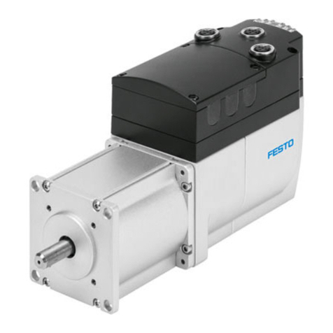
EMCA-EC-67-...-EC/-EP/-PN
Integrated drive
8127103
202003b
[8127105]
Brief instructions
Festo SE & Co. KG
Ruiter Straße 82
73734 Esslingen
Germany
+49 711 3470
www.festo.com
Range of application and approvals
The EMCA with integrated STO safety function is a safetyrelated part of control
systems. The product has the CE marking. Certain configurations of the product
are certified by Underwriters Laboratories Inc. (UL).
Certificates and declaration of conformity for the product èwww.festo.com/sp.
Specified standards
Editions
IEC 62061:2015 ISO 138491:2015 EN 6180052:2007
Tab. 2
3.1 Transport and storage conditions
– Protect the product from excessive stress factors during transport and stor
age. Excessive stress factorsinclude:
– mechanical stresses
– impermissible temperatures
– moisture
– aggressive atmospheres
– Store and transport the product in its original packaging. The original pack
aging offers sufficient protection from typical stresses.
3.2 Technical prerequisites
For correct and safe use of the product:
– Comply with the specified connection and ambient conditions for all connec
ted components è 10 Technical data. Only compliance with the limit values
and/or load limits will enable operation of the product in accordance with the
relevant safety directives.
4 Product description
4.1 Product overview
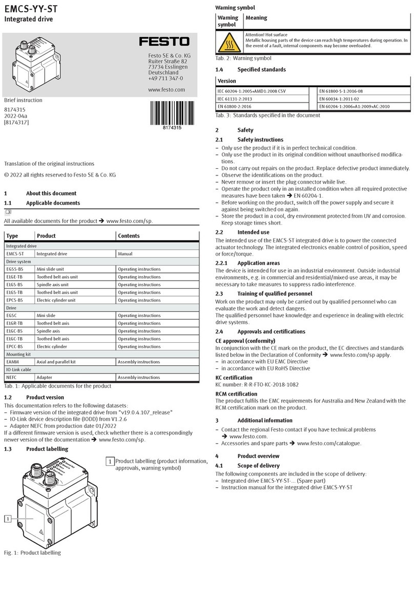
1LED light guides (6x)
2[X1]: parameterisation interface
(Ethernet interface)
3[X3]: IN
EtherCAT, EtherNet/IP, PROFINET:
port 1
4Cable throughfeeds (6x)
5Motor flange
6Throughhole for mounting (4x)
7Mounting thread (4x) thread M4
8Shaft
9Cover
10 [X2]: OUT
EtherCAT, EtherNet/IP, PROFINET:
port 2
Fig. 1 Design of the drive
Fig. 2 View with cover open
1[X5]: braking resistor
2[X10]: external battery (…1TM)
3[X6]: STO interface
4[X9]: I/O interface
5[X8]: reference or limit switch 2
6[X7]: reference or limit switch 1
7FE connection (flat plug)
8[X4]: power supply
Functions of the LEDs – dependent on the product variant
LED EMCAEC67...EC
(EtherCAT)
EMCAEC67...EP
(EtherNet/IP)
EMCAEC67...PN
(PROFINET)
9LINK/ACTIVITY, port 2
aJ OK
aA ERROR
aB EC RUN MS (Module status) IDENT/STATE
(Identification/Status)
aC EC ERROR NS (Network status) NF (Network failure)
aD NK/ACTIVITY, port 1
Tab. 3
5 Assembly
The mounting flange offers the following options for mounting:
– Mounting via 4 throughholes for screws of sizeM6
– Mounting via 4 M4 female threads (screwin depth: 5mm).
Observe the assembly instructions for the additional components used (e.g.axial
kit, parallel kit, gear unit, axis).
The drive must be mounted securely and without tension.
1. Move the slide or cantilever of the driven mechanism into a safe position.
2. Connect the EMCA to the driven mechanism èAssembly instructions for the
additional components.
3. Tighten the retaining screws (4x). Tightening torque è Assembly instruc
tions for the additional components.
6 Electrical installation
WARNING!
Risk of injury due to unexpected movement of the product.
Electrical energy can cause unexpected movement of the product.
• Before working on the product: Switch off the power supply, ensure that it is
off and secure it against being switched on again.
6.1 Connections and cables
NOTICE!
Unexpected and unintended movements
Incorrectly assembled cables can cause malfunctions.
• Use only the supplied plugs and preferably the cables listed in the specified
accessories.
• Lay all flexible cables so that they are free of kinks and mechanical stress,
e.g.in a carrier chain.
ESD protection
Damage may be caused to the product or to other system parts at unassigned
pushin connectors as a result of ESD (Electrostatic Discharge).
– Comply with the handling specifications for electrostatically sensitive devices.
– Seal unassigned plugs with protective caps.
– Earth system parts prior to installation.
The mating plugs for the plug connectors are not included in the scope of delivery
(assortment of plugs NEKMC).
6.2 Parameterisation interface (Ethernet) [X1] – M12 bushing, 5-pin,
D-coded
Connect EMCA to your network via a hub/switch or directly to the PC. Observe line
specification èDevice and function description, EMCAECSY….
Recommended: use connecting cable NEBCD12G4… from Festo.
NOTICE!
Unauthorised Access to the Device Can Cause Damage or Malfunction.
• When connecting the device to a network, protect the network from unauthor
ised access.
Standards for security in information technology can be used for network pro
tection measures,e.g. IEC62443, ISO/IEC27001.
[X1] Pin Description
1 TD+ Transmitted data +
2 RD+ Received data +
3 TD Transmitted data –
4 RD Received data –
5 – Not connected
[X1] Pin Description
Housing Shield/FE Shield/functional earth
Tab. 4
6.3 Bus/network [X2], [X3] - depending on product variant
– [X2]: OUT (port 2) – M12 bushing, 5pin, Dcoded
– [X3]: IN (Port 1) – M12 bushing, 5pin, Dcoded
[X2], [X3] Pin Description
1 TD+ Transmitted data +
2 RD+ Received data +
3 TD Transmitted data –
4 RD Received data –
5 nc Not connected
Housing Shield/FE Shield/functional earth
Tab. 5
6.4 Power supply [X4]
WARNING!
Risk of injury due to electric shock.
• For the electrical power supply, use only PELV circuits in accordance with IEC
602041/EN 602041 (Protective ExtraLow Voltage, PELV).
• Observe the general requirements of IEC 602041/EN602041 for PELV cir
cuits.
• Only use voltage sources that ensure a reliable electric separation from the
mains network in accordance with IEC 602041/EN 602041.
[X4] Pin Description
1 +24 V DC Power supply (logic and load voltage)
+19.2 V DC…+28.8 V DC
2 0V GND, reference potential
Tab. 6
If a shielded supply cable is used, the cable shield can be connected to the func
tional earth connection (flat plug).
Flat plug Pin Description
– FE Optional connection for the cable screening
Mating connector: flat connector sleeve (6.3 x
0.8 mm2)
Tab. 7
6.5 Braking resistor [X5]
[X5] Pin Description
1 ZK+
2 BRCH
Connection for the external braking resistor RBR 6 Ω; the
braking resistor CACRLE26W60 from Festo is suitable.
Tab. 8
6.6 STO interface [X6]
The STO safety function is described in detail in the EMCAECS1… document. The
STO function should only be used in the manner described in this document.
Recommendation for initial motor startup without safety engineering:
– minimum circuitry with emergency stop switching device
– 2channel switchoff via the control inputs STO1 [X6.4] and STO2 [X6.5]
[X6] Pin Description
1 NC1
2 NC2
Feedback contact:
– potentialfree
– low impedance if the STO function has been
requested and activated via 2 channels.
3 +24 V DC
LOGIC OUT
Logic voltage output (from [X4.1]), reference potential
(0V) is pin [X6.6] or [X4.2] (internally bridged)
Not overloadproof! Max.100mA permissible.
4 STO 1
5 STO 2
Control inputs for STO function
6 GND Reference potential 0V
Tab. 9
6.7 Limit/reference switch [X7], [X8]
[X7] Pin Description
1 +24 V DC Voltage output 24V for supply of the reference or
limit switch 1 (configurable with FCT, not shortcircuit
proof).
2 Switch 1 Signal input for reference switch or limit switch 1
3 GND Reference potential 0V
Tab. 10
[X8] Pin Description
1 +24 V DC Voltage output 24V for supply of the reference or limit
switch2 (configurable with FCT, not shortcircuit proof).
2 Switch 2 Signal input for reference switch or limit switch2
3 GND Reference potential 0V
Tab. 11
6.8 I/O interface [X9]
[X9] Pin Type1) Name Description
1 DOUT Ready signals the ready status
2 DOUT Configur
able
Output behaviour configurable with FCT
3 – 24 V DC Output 24 V DC; looped through from
[X4.1]
4 DIN Enable Enable/block closedloop controller
5 DIN Sample Signal for storing the actual position (ad
hoc measurement)
6 – GND Reference potential 0V
1) DIN = digital input; DOUT = digital output
Tab. 12
6.9 External battery [X10] - only EMCA-EC -...- 1TM
[X10] Pin Description
1 Battery +
2 Battery –
(GND)
Connection for external battery (position changes are
recorded for a maximum of 7 days (best case) without
supply voltage and without battery (after charging for
approx.24hours)). With the EADAA9 battery from
Festo the duration can be extended to a maximum of 6
months.
Tab. 13
– Comply with the requirements for securing the IP degree of protection
èDevice and function description, EMCAECSY….
7 Commissioning
The product communicates with a connected PC with the TCP/IPv4 protocol.
Establishing network connection – example “point-to-point connection”
Requirement:
– The PC is configured as a DHCP client (usually the default setting for PCs).
– The EMCA is configured as a DHCP server (factory setting).
– At initial commissioning connect the EMCA directly to the PC.
Factory setting
DHCP server: active
IP address: http://192.168.178.1
Subnet mask: 255.255.255.0
Gateway:  (a gateway is not assigned.)
Web server
The integrated web server provides read access to an Englishlanguage website.
FCT (Festo Configuration Tool)
The EMCA plugin for the Festo Configuration Tool (FCT) supports all the steps
necessary for commissioning of the device.
Comply with the documentation for the product èwww.festo.com/sp.
Before switching on the power supply:
Check installation:
– Check all connections.
Check readiness for operation
1. Make sure that controller enable signal is switched off (pin X9.4).
2. Switch on the power supply. The OK LED on the front panel of the device
should now flash green.
If the OK LED stays off, the device is not ready for operation. If the ERRORLED
shows red, an error is reported and the cause of the error must be remedied.
Further steps for commissioning èHelp for the EMCA plugin and device and
function description EMCAECSY…
8 Diagnostics and fault clearance
Information on the busspecific LEDs (MS, NS, ACT/LINK) èDescription of the
device profile.
LED LED status Event/status
Behaviour during the switchon phase
OK green flashing
ERROR red flashing
Startup phase, bootloader active
Behaviour in the operating phase
OK Off Hardware is not ready for operation; an error is pending.
LED LED status Event/status
green flashing Hardware is ready for operation; but the “Enable” signal is
not pending.
OK
green Normal operating status; hardware is ready for operation;
“Enable” signal is pending.
Off no error, no warning
red flashing A warning is indicated.
ERROR
red An error is reported.
Identification sequence active
OK
ERROR
simultaneous
flashing
Feedback for optical identification active
(can be activated via the web server)
Behaviour with errors in the firmware update phase
OK Off
ERROR red flashing
Firmware update was cancelled due to an error.
Tab. 14
9 Cleaning, repair and disposal
Clean the outside of the product with a soft cloth.
Repair or maintenance of the product is not permissible. If necessary, replace the
complete product.
Observe the local regulations for environmentally friendly disposal of electronic
components.
10 Technical data
Further technical data can be found in the following documents:
• Detailed technical data for the STO interface èDescription of the STO safety
function EMCAECS1…
• Additional technical data èDevice and function description EMCAECSY…
• Requirements for complying with the certified UL conditions if the product is
operated in the USA or Canada can be found in the separate UL special docu
mentation.
Safety reference data and safety specifications
Safety function STO Safe Torque Off (safe torque off)
Category 3 in accordance with ISO 138491
Performance level PL d in accordance with ISO 138491
Safety Integrity Level SIL 2 in accordance with EN 6180052 (safety
integrity level)
SIL Claim Limit SILCL 2 in accordance with IEC 62061 (SIL claim limit)
DCavg [%] 90 Average diagnostic coverage
(Average diagnostic coverage)
HFT 1 Hardware failure tolerance
(hardware fault tolerance)
SFF [%] > 90 Safe Failure Fraction (safe failure fraction)
PFHD[1/hr] 1 x 109 Probability of dangerous failure per hour
(probability of dangerous failure per hour)
T
Proof Test Interval [years] 20 Test interval
Service life [years] 20 in accordance with ISO 138491
Type test The STO function has been certified by an independent
testing body. EMCA certificate èwww.festo.com/sp
Tab. 15 Safety reference data and safety specifications
General Technical Data EMCA-…-S-…EMCA-…-M-…
Environmental and operating conditions
Mounting position any
at nominal power: 0…20Ambient temperature [°C]
with power reduction 1.75% per °C: 20…50
Storage temperature [°C] –25…+70
Relative humidity at 25 °C [%] 0…95 (noncondensing)
Degree of protection EMCA... (without
S1)
EMCA...S1
IP54
IP65; motor shaft IP54
Protocol EtherCAT or EtherNet/IP or PROFINET
Communication profile EtherNet/IP, PROFINET: FHPP
EtherCAT: FHPP, CiA402
Power supply [X4]
Nominal voltage [V DC] 24
Permissible voltage fluctuations [%] ± 20 –
Nominal current [A] 6.9 7.2
Peak current [A] 10.2 10.3
Rotor position encoder Absolute singleturn
encoder
Absolute multiturn
encoder
Resolution [bit] 12 (4096 increments
per revolution)
12 bits (4096 incre
ments per revolution)
and 4,294,967,729 (±
2,147,483,648)
revolutions; 32 bit
Absolute encoder operating duration (at medium ambient temperature)
without external battery
The maximum storage period depends on the charge
status of the internal capacitor, the ambient temper
ature and ageing effects.
– 3 days (worst case);
maximum of 7 days
(best case)
with external battery
The maximum service life of the battery depends on
the state of charge, ambient temperature and ageing
effects.
– maximum 6 months
Digital inputs/outputs
Switching logic inputs/outputs PNP (positive switching)
Characteristics of digital logic outputs freely configurable in some cases
Not galvanically isolated
Peak current to digital logic outputs [mA] 100
Characteristics of logic inputs Galvanically connected to logic potential
Specification of logic inputs Based on IEC 611312
Operating range of logic input [V DC] 24
Motor data
Nominal power [W] 120 150
Nominal torque [Nm] 0.37 0.45
Nominal rotary speed [rpm] 3100 3150
Max. rotational speed [rpm] 3500 3300
Mass moment of inertia of rotor [kgcm2] 0.175 0.301
Perm. axial shaft load [N] 60 60
Perm. radial shaft load [N] 100 100
Holding brake (only EMCAEC……B)
Brake holding torque [Nm] 1
Brake power consumption [W] 9
Mass moment of inertia, brake [kgcm2] 0.021
Max. line lengths (for ensuring EMC conformity)
Power supply line [m] £ 30
STO and I/O interface [m] £ 30
Limit/reference switch, battery [m] £ 3
Product weight (without [B], without
[M])1)
[g] 1900 2260
Product conformity and approvals
CE marking (Declaration of Conformity
èwww.festo.com/sp)
In accordance with EU Machinery Directive
In accordance with EUEMC Directive 2)
Approvals3) RCM (Regulatory Compliance Mark)3)
c UL us – Recognized (OL)3)
1) holding brake [B] +350 g, multiturn absolute measurement system [M] +25 g
2) The device is intended for industrial use. Measures may need to be implemented in residential areas for
radio interference suppression.
3) only valid for product variants with corresponding marking
Tab. 16

Other manuals for EMCA-EC-67 CO Series

11

This manual suits for next models

3

Other Festo DC Drive manuals

Festo DNG Series Setup guide

Festo

Festo DNG Series Setup guide

Festo EMCA-EC-67 CO Series User manual

Festo

Festo EMCA-EC-67 CO Series User manual

Festo DAPS Series User manual

Festo

Festo DAPS Series User manual

Festo DFPI ND2P-E-NB3P Series User manual

Festo

Festo DFPI ND2P-E-NB3P Series User manual

Festo SLG-8 Series User manual

Festo

Festo SLG-8 Series User manual

Festo DRVS-6 User manual

Festo

Festo DRVS-6 User manual

Festo DGCI Series User manual

Festo

Festo DGCI Series User manual

Festo EMCA-EC-67 CO Series User manual

Festo

Festo EMCA-EC-67 CO Series User manual

Festo CMMT-AS-C2-11A-P3 S1 Series User manual

Festo

Festo CMMT-AS-C2-11A-P3 S1 Series User manual

Festo DNCM POT Series User manual

Festo

Festo DNCM POT Series User manual

Festo ERMO Series User manual

Festo

Festo ERMO Series User manual

Festo EGC-50-TB Parts list manual

Festo

Festo EGC-50-TB Parts list manual

Festo CMMT-ST-C8-1C-...-S0 Series User manual

Festo

Festo CMMT-ST-C8-1C-...-S0 Series User manual

Festo Type SLM-Series-KF-A User manual

Festo

Festo Type SLM-Series-KF-A User manual

Festo TP 1422 Operation instructions

Festo

Festo TP 1422 Operation instructions

Festo DDLI-25 User manual

Festo

Festo DDLI-25 User manual

Festo DFPI-...D2P-C1V-NB3P series User manual

Festo

Festo DFPI-...D2P-C1V-NB3P series User manual

Festo FKP Series User manual

Festo

Festo FKP Series User manual

Festo DGCI Series User manual

Festo

Festo DGCI Series User manual

Festo DNCE-***-LAS User manual

Festo

Festo DNCE-***-LAS User manual

Festo DFPD-HD-RD Series Parts list manual

Festo

Festo DFPD-HD-RD Series Parts list manual

Festo DGC-8 Series User manual

Festo

Festo DGC-8 Series User manual

Festo DFPI-***-***-ND2P-E-P-G2 User manual

Festo

Festo DFPI-***-***-ND2P-E-P-G2 User manual

Festo ERMS Parts list manual

Festo

Festo ERMS Parts list manual

Popular DC Drive manuals by other brands

DINAMIC OIL TA Series user manual

DINAMIC OIL

DINAMIC OIL TA Series user manual

Danfoss VLT HVAC Drive FC 102 installation instructions

Danfoss

Danfoss VLT HVAC Drive FC 102 installation instructions

Eaton Cutler Hammer PowerXL DC1 E1 Series Parameter manual

Eaton

Eaton Cutler Hammer PowerXL DC1 E1 Series Parameter manual

Rockwell Automation Reliance Electric MD65 user manual

Rockwell Automation

Rockwell Automation Reliance Electric MD65 user manual

Siemens SINAMICS SM150 Operating and installation instructions

Siemens

Siemens SINAMICS SM150 Operating and installation instructions

Rexnord Falk Quadrive A Mounting & installation

Rexnord

Rexnord Falk Quadrive A Mounting & installation

ZIEHL-ABEGG ZA dyn 4B 110 Original operating instructions

ZIEHL-ABEGG

ZIEHL-ABEGG ZA dyn 4B 110 Original operating instructions

GFA ELEKTROMAT SI 40.15-40,00 Ex installation instructions

GFA

GFA ELEKTROMAT SI 40.15-40,00 Ex installation instructions

Bosch BDU3740 owner's manual

Bosch

Bosch BDU3740 owner's manual

Texas Instruments BOOATXL-DRV8301 user guide

Texas Instruments

Texas Instruments BOOATXL-DRV8301 user guide

YASKAWA CANopen SI-S3 Technical manual

YASKAWA

YASKAWA CANopen SI-S3 Technical manual

SOMFY JR RU 30 instructions

SOMFY

SOMFY JR RU 30 instructions

Honeywell CORE Drive quick start guide

Honeywell

Honeywell CORE Drive quick start guide

Rhymebus RM6E1 Series Operation manual

Rhymebus

Rhymebus RM6E1 Series Operation manual

Unimotion MCE Assembly and maintenance instructions

Unimotion

Unimotion MCE Assembly and maintenance instructions

Toshiba ATAPI installation manual

Toshiba

Toshiba ATAPI installation manual

HATO 300 SILENT 1000N operating manual

HATO

HATO 300 SILENT 1000N operating manual

ABB ACS880-01 Series Quick installation guide

ABB

ABB ACS880-01 Series Quick installation guide

manuals.online logo
manuals.online logoBrands
  • About & Mission
  • Contact us
  • Privacy Policy
  • Terms and Conditions

Copyright 2025 Manuals.Online. All Rights Reserved.