Leadshine ELD2-RS70 Series User manual


2
ELD2-RS70** User Manual
Introduction
Thanks for purchasing Leadshine ELD2-series low-voltageAC servo drivers, this instruction
manual provides knowledgeand attention forusing this driver.
Contact tech@leadshine.com for more technical service .
Incorrect operation may cause unexpected accident, please read this manual carefully
before using product.
We reserve the right to modify equipment and documentation without prior notice.
We won’t undertake any responsibility with customer’s any modification of product, and the
warranty of product will be cancel at the same time.
Be attention to the following warning symbol:
Warning indicates that the error operation could resultin loss of life or serious injury.
Caution indicates that the error operation could result in operator injured, also make
equipment damaged.
Attention indicates that the error use may damage product and equipment.
Safety precautions
Warning
⚫The design and manufacture of product doesn’t use in mechanic and system which have a threat to
operator.
⚫The safety protection must be provided in design and manufacture when using thisproduct to
prevent incorrect operation or abnormal accident.
Acceptance
Caution
⚫The product which is damaged or have fault is forbidden to use.
Transportation
Caution
⚫The storage and transportation must be in normal condition.
⚫Don’t stack too high, prevent falling.
⚫The product should be packaged properly in transportation,
⚫Don’t hold the product by the cable, motor shaft or encoder while transporting it.
⚫The product can’t undertake external force and shock.
Installation
Caution
Servo Driver and Servo Motor:
⚫Don’t install them on inflammable substance or near it to preventing fire hazard.
⚫Avoid vibration, prohibit direct impact.

3
ELD2-RS70** User Manual
⚫Don’t install the product while the product is damaged or incomplete.
Servo Driver:
⚫Must install in control cabinet with sufficient safeguarding grade.
⚫Must reserve sufficient gap with the other equipment.
⚫Must keep good cooling condition.
⚫Avoid dust, corrosive gas, conducting object, fluid and inflammable, explosive object from
invading.
Servo Motor:
⚫Installation must be steady, prevent drop from vibrating.
⚫Prevent fluid from invading to damage motor and encoder.
⚫Prohibit knocking the motor and shaft, avoid damaging encoder.
⚫The motor shaft can’t bear the load beyond the limits.
Wiring
Warning
⚫The workers of participation in wiring or checking must possess sufficient ability do this job.
⚫Ground the earth terminal of the motor and driver without fail.
⚫The wiring should be connected after servo driver and servo motor installed correctly.
⚫After correctly connecting cables, insulate the live parts with insulator.
Caution
⚫The wiring must be connected correctly and steadily, otherwise servo motor may run incorrectly, or
damage the equipment.
⚫We mustn’t connect capacitors, inductors or filters between servo motor and servo driver.
⚫The wire and temperature-resistant object must not be close to radiator of servo driver and motor.
⚫The freewheel diode which connect in parallel to output signal DC relay mustn’t connect reversely.
Debugging and running
Caution
⚫Make sure the servo driver and servo motor installed properly before power on, fixed steadily,
power voltage and wiring correctly.
⚫The first time of debugging should be run without loaded, debugging with load can be done after
confirming parameter setting correctly, to prevent mechanical damage because of error operation.
Caution
⚫Install a emergency stop protection circuit externally, the protection can stop running immediately to
prevent accident happened and the power can be cut off immediately.
⚫The run signal must be cut off before resetting alarm signal, just to prevent restarting suddenly.
⚫The servo driver must be matched with specified motor.
⚫Don’t power on and off servo system frequently, just to prevent equipment damaged.
⚫Forbidden to modify servo system.
Fault Processing
Caution
⚫The reason of fault must be figured out after alarm occurs, reset alarm signal before restart.

4
ELD2-RS70** User Manual
⚫Keep away from machine, because of restart suddenly if the driver is powered on again after
momentary interruption(the design of the machine should be assured to avoid danger when restart
occurs)
System selection
Attention
⚫The rate torque of servo motor should be larger than effective continuous load torque.
⚫The ratio of load inertia and motor inertia should be smaller than recommended value.
⚫The servo driver should be matched with servo motor.

5
ELD2-RS70** User Manual
Table of Contents
Introduction..............................................................................................................................2
Chapter 1 Introduction...............................................................................................................7
1.1 Product Introduction......................................................................................................7
1.2 Inspection of product.....................................................................................................8
Chapter 2 Installation.................................................................................................................9
2.1 Storage and Installation Circumstance..............................................................................9
2.2 Servo Driver Installation................................................................................................9
2.2.1 Installation Method..............................................................................................9
2.2.2 Installation Space...............................................................................................10
2.3 Servo Motor Installation............................................................................................... 11
Chapter 3 Wiring.....................................................................................................................12
3.1 Wiring.......................................................................................................................12
3.1.1 Wire Gauge.......................................................................................................12
3.1.2 Position Control Mode .......................................................................................13
3.2 Driver Terminals Function............................................................................................14
3.2.1 Control Signal Port-CN1 Terminal.......................................................................14
3.2.2 Encoder Input Port-CN2 Terminal........................................................................15
3.2.3 Communication Port..........................................................................................16
3.2.4 Power Port........................................................................................................16
3.2.5 Bus connector...................................................................................................16
3.2.6 Dip switch........................................................................................................16
3.3 I/O Interface Principle..................................................................................................17
3.3.1 Switch Input Interface........................................................................................17
3.3.2 Switch Output Interface......................................................................................17
3.3.3 Pulse Input Interface..........................................................................................18
Chapter 4 Parameter.................................................................................................................20
4.1 Parameter List.............................................................................................................20
4.2 Parameter Function......................................................................................................22
4.2.1【Class 0】Basic Setting.....................................................................................22
4.2.2【Class 1】Gain Adjust ......................................................................................25
4.2.3【Class 2】Vibration Suppression........................................................................30
4.2.4【Class 3】Velocity/ Torque Control *..................................................................31
4.2.5【Class 4】I/F Monitor Setting............................................................................36
4.2.6【Class 5】Extended Setup.................................................................................41
4.2.7【Class 6】Special Setup....................................................................................43
Chapter 5 Alarm and Processing................................................................................................45
5.1 Alarm List..................................................................................................................45
5.2 Alarm Processing Method.............................................................................................46
Chapter 6 Trial Run .................................................................................................................54
6.1 Inspection Before trial Run...........................................................................................54
6.1.1 Inspection on wiring...........................................................................................54
6.1.2 Timing chart on power-up...................................................................................55
6.1.3 Timing chart on fault..........................................................................................55
6.1.4 Holding brake...................................................................................................55
6.2 Trial Run....................................................................................................................56
6.2.1 Position Control................................................................................................56
6.3 Automatic Control Mode Run.......................................................................................57
6.3.1 Operation Mode Selection...................................................................................57
6.3.2 Position Mode...................................................................................................57
Chapter 7 PR function..............................................................................................................61
7.1 Overview...................................................................................................................61
7.1.1 Main function....................................................................................................61
7.1.2 Installation wiring..............................................................................................62
7.2 Parameter...................................................................................................................64
7.2.1 8th sort parameters specification..........................................................................64

6
ELD2-RS70** User Manual
7.2.2 9th sort parameters specification..........................................................................66
7.3 IO Operation mode......................................................................................................67
7.3.1 Homing............................................................................................................67
7.3.2 Trigger path......................................................................................................69
7.3.3 Position limit, JOG and E-stop function................................................................72
7.4 Communication control mode.......................................................................................73
7.4.2 485 communication Installation wiring................................................................. 75
7.4.3 Fixed trigger mode.............................................................................................76
7.4.4 Immediately trigger method................................................................................77
7.4.5 Test Pr-Mode with Serial debugging assistant ........................................................78
7.5 Upper computer operation............................................................................................83
7.6 RS485 Parameter address.............................................................................................85
Chapter 8 Product Specification.................................................................................................90
8.1 Driver Technical Specification......................................................................................90
8.2 Accessory selection .....................................................................................................90
Appendix................................................................................................................................91
Quick guide for tuning the servo.........................................................................................91
Contact us ..............................................................................................................................92

7
ELD2-RS70** User Manual
Chapter 1 Introduction
1.1 ProductIntroduction
ELD2 low-voltageAC servo is a special motion control product designed for machines and
applications that request a best balance between outstanding and reasonable cost.
Combined with abundant features like MFC, vibration suppression, Multi-mode filter function etc.
It providemachines a compact size, low tuning works, but high resolution encoder up to 5000 lines, an
unique servo system.
Talent feature:
◆Easy tuning
◆Automatic identification for motor
◆Simple, flexible to control
◆RS485/Modbus/CANopen
◆Notch filter, damping filter
◆Optional feedback
Specifications
Driver model
ELD2-RS7010
ELD2-RS7015
ELD2-RS7020
ELD2-RS7030
Size(mm)
118*75.5*34
159*98*33
159*98*33
159*98*33
Rated power(kw)
0.4
0.6
0.75
1.2
Rated output current(A)
10
15
20
30
Max output current(A)
30
45
60
90
Main
power
Voltage(V)
DC24-70(recommended 24-60Vdc)
Current(A)
48-60Vdc:
7Amp
60-70Vdc:
6Amp
48-60Vdc:
11Amp
60-70Vdc:
9Amp
48-60Vdc:
14Amp
60-70Vdc:
12Amp
48-60Vdc:
20Amp
60-70Vdc:
17Amp
Control
power
Voltage(V)
DC12-24
DC12-24
DC12-24
DC12-24
Current(mA)
≥12
≥12
≥12
≥12
Control method
IGBT PWM sinusoidal Wave Drive
Overload
300%
Brake resistor
External connection
Protection rank
IP20
Features
Driver model
ELD2-RS7010B
ELD2-RS7015B
ELD2-RS7020B
ELD2-RS7030B
Pulse input
2 fast pulse input, 5V only, 300kHz
Modes of operation
Position/Velocity/Torque
Command source
Pulse+Direction
/RS485
Pulse+Direction/±10 V Analog/RS485
Inputs/Outputs
2 programmable differential inputs(5V);
7 programmable single-end inputs(24V);
2 programmable differential outputs;
3 programmable single-end outputs;
1 analog input(±10 V).(not for7010B)
Feedback Supported
1000. 2500lines incremental TTL encoder
Encoder(ABZ)+Hall(UVW)、Encoder(ABZ)
Communication
Supported
RS-485/ RS-232/ Modbus-RTU

8
ELD2-RS70** User Manual
1.2 Inspectionofproduct
1. You must check thefollowing thing before using the products :
a. Check if the product is damaged or not during transportation.
b. Check if the servo driver & motor are complete or not.
c. Check the packing list if the accessories are complete or not
2. Type meaning
a. ELD2 series servo driver
ELD2-RS7010 B
Brake
Maximum Output Power
7010: 70Vdc/10Arms,30Amp peak
7015: 70Vdc/15Arms,45Amp peak
7020: 70Vdc/20Arms,80Amp peak
7030: 70Vdc/30Arms,90Amp peak
RS: RS485(Pulse+Dir/Analog Input/Modbus)
CAN: CANopen
Low-voltage AC servo drive
b. Servo motor type
The ELD2 series AC servo driver can be matched with a variety of domestic and foreign servo motor.
Matched Motors
Power Range
Up to 1200W
Voltage Range
24 - 70V
Feedback supported
1000. 2500lines incremental TTL encoder ;
17bit and 23bit Serial signal encoder.
Motor Size
40mm,42mm,57mm,60mm,80mm frameor other size
Other Requirements
Brake. oil-seal. protection level. shaft&connector can be customized

9
ELD2-RS70** User Manual
Chapter 2 Installation
2.1 StorageandInstallationCircumstance
Table 2.1 Servo Driver, Servo Motor StorageCircumstance Requirement
Item
ELD2 series driver
ELDM low voltage servo motor
Temperature
-20-80℃
-25-70℃
Humility
Under 90%RH (free from condensation)
Under 80%RH(free from condensation)
Atmospheric
environment
Indoor(no exposure)no corrosive gas or
flammable gas, no oil or dust
Indoor(no exposure)no corrosive gas or
flammable gas, no oil or dust
Altitude
Lower than 1000m
Lower than 2500m
Vibration
Less than 0.5G (4.9m/s2) 10-60Hz (non-continuous working)
Protection
level
IP00(no protection)
IP54
Table 2.2 Servo Driver, Servo MotorInstallation Circumstance Requirement
Item
ELD2 series driver
ELDM low voltage servo motor
Temperature
0-55℃
-25-40℃
Humility
Under 90%RH(free from condensation)
Under 90%RH(free from condensation)
Atmospheric
environment
Indoor(no exposure)no corrosive gas or
flammable gas, no oil or dust
Indoor(no exposure)no corrosive gas or
flammable gas, no oil or dust
Altitude
Lower than 1000m
Lower than 2500m
Vibration
Less than 0.5G (4.9m/s2) 10-60Hz (non-continuous working)
Protection
level
IP00(no protection)
IP54
2.2 Servo DriverInstallation
Notice
⚫Must install in control cabinet with sufficient safeguarding grade.
⚫Must install with specified direction and intervals, and ensure good cooling condition.
⚫Don’t install them on inflammable substance or near it to prevent fire hazard.
2.2.1 Installation Method
Install in vertical position ,and reserve enough space around the servo driver for ventilation.
Here is the installation diagram:
Figure 2.1(A) installation method of driver ELD2-RS7010
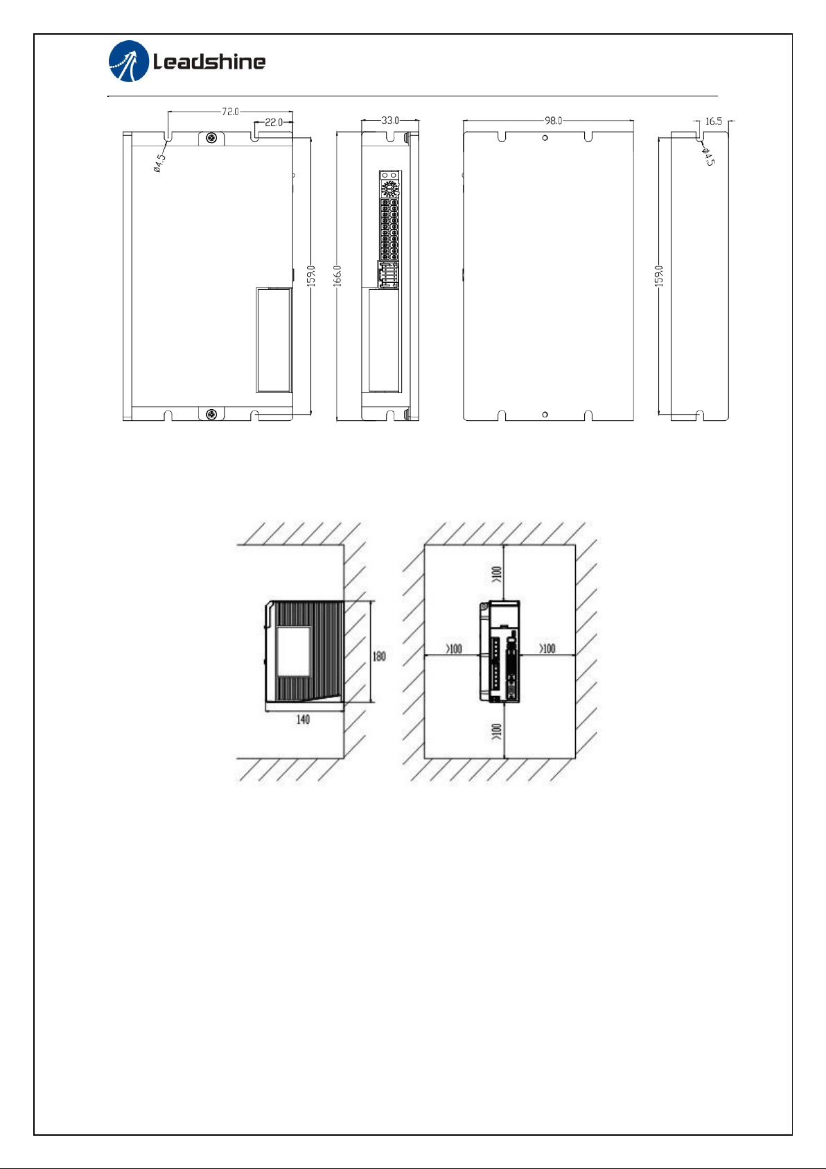
10
ELD2-RS70** User Manual
Figure 2.1(B) installation method of driver ELD2-RS7015 /ELD2-RS7020/ELD2-RS7030
2.2.2 Installation Space
Reserve enough surrounding space for effective cooling.
Figure 2.2 Installation Spacefor Single Driver

11
ELD2-RS70** User Manual
Figure 2.3 Installation Spacefor severalDrivers
2.3 Servo MotorInstallation
Notice
⚫Don’t hold the product by the cable, motor shaft or encoder while transporting it.
⚫No knocking motor shaft or encoders, prevent motor by vibration or shock.
⚫The motor shaft can’t bear the load beyond the limits.
⚫Motor shaft does not bear the axial load, radial load, otherwise you may damage the motor.
⚫Use a flexible with high stiffness designed exclusively for servo application in order to make
a radial thrust caused by micro misalignment smaller than the permissible value.
⚫Install must be steady, prevent drop from vibrating.

12
ELD2-RS70** User Manual
Chapter 3 Wiring
Warning
⚫The workers of participation in wiring or checking must possess sufficient ability do this job.
⚫The wiring and check must be going with power off after five minutes.
Caution
⚫Ground the earth terminal of the motor and driver without fail.
⚫The wiring should be connected after servo driver and servo motor installed correctly
3.1 Wiring
3.1.1 Wire Gauge
(1)Power supply terminal TB
● Diameter:
Driver
Wire diameter (mm2/AWG)
Vdc,GND
U.V.W
PE
ELD2-*7010
2.627/AWG13
2.627/AWG13
2.1/AWG14
ELD2-*7015
2.627/AWG11
2.627/AWG11
2.1/AWG14
ELD2-*7020
5.26/AWG10
5.26/AWG10
2.1/AWG14
ELD2-*7030
8.37/AWG8
8.37/AWG8
2.1/AWG14
● Grounding: The grounding wire should be as thick as possible, drive servo motor the PE terminal
point ground, ground resistance <100 Ω.
●Use noise filter to remove external noise from the power lines and reduce an effect of the noise
generated by the servo driver.
● Install fuse (NFB) promptly to cut off the external power supply if driver error occurs.
(2) The control signal CN1 feedback signal CN2
● Diameter: shielded cable (twisting shield cable is better), the diameter ≥ 0.14mm2(AWG24-26), the
shield should be connected to FG terminal.
● Length of line: cable length should be as short as possible and control CN1 cable is no more than 3
meters, the CN2 cable length of the feedback signal is no morethan 20 meters.
● Wiring: be away from the wiring of power line, to prevent interferenceinput.
●Install a surge absorbing element for the relevant inductive element (coil),: DC coil should be in
parallel connection with freewheeling diode reversely; AC coil should be in parallel connection with
RC snubber circuit.
Attention
⚫Match the colors of themotor lead wires to those of the corresponding motor output terminals
(U.V.W)
⚫Never start nor stop the servo motor with this magnetic contactor.

13
ELD2-RS70** User Manual
3.1.2 Position Control Mode
CN1
5
COM_IN
ENA
CLR
12~24Vdc
(input)
RS232
Conmunication
port
1
PUL+
2
PUL-
3
DIR+
270Ω
4
DIR-
CN2
U
PE
W
V
6
7
Vdc
GND
DC power supply
+
-
RS485*2
270Ω
4.7K
4.7K
4.7K
4.7K
NOT 9
DOT 8
10
11
12
13
A-
15
B-
B+ 14
16
COM_OUT
24Vdc
(output)
18
19
20
DO1
DO2
VIN+
VIN-
Analog
Input
A+
Encoder
Output
17
DO+
DO-
Brake
Output
Pulse
signal
Figure 3-1 PositionalControl Mode Wiring
Attention:
1、Only support 5V pulse and direction signal , 24V pulse signal suggest connect 2 KΩresistance

14
ELD2-RS70** User Manual
270R
DIR+
DIR-
PUL+
PUL-
270R
Driver side
Pulse InputInterfaceDifferential Drive Mode
Pulse InputInterfaceSingleTerminal Drive Mode
3.2 DriverTerminalsFunction
3.2.1 Control Signal Port-CN1 Terminal
The left on Figure 3.3 is control signal port CN1 of servo driver with Molex-20 connector;
Table 3.1 Signal Explanation of ControlSignal Port-CN1
CN1
Pin
Signal
IO
Detail
CN1
1
DI1+
Input
Positive differential pulse input,5V,
500KHz
GPIO/
Pulse
2
DI1-
Input
Negative differential pulse input,5V,
500KHz
3
DI2+
Input
Positive differential pulse input,5V,
500KHz(Optional analog Ain1+)
GPIO/
Direction/
Analog
4
DI2-
Input
Negative differential pulse input,5V,
500KHz(Optional analog GND)
5
COMI
Input
Power supply positive terminal of the external input
control signal, 12V ~ 24V
6
DI3
Input
Digital input signal 3, default value is forward
enable signal , low level available in default , max
voltage is 24V input 20KHz
7
DI4
Input
Digital input signal 4, default value is alarm clear
signal , low level available in default , max voltage
is 24V input 20KHz

15
ELD2-RS70** User Manual
8
DI5
Input
Digital input signal 5, default value is forward run
prohibited (POT)signal in position mode , low level
available in default , max voltage is 24V input
20KHz
9
DI6
Input
Digital input signal 6, default value is reverse run
prohibited (NOT) signal in position mode , low
level available in default , max voltage is 24V input
20KHz
10
Vin+
Input
Analog input, voltage input range :
-10VDC~+10VDC , input resistor 20KΩ.
11
Vin-
Input
12
A+
Output
Differential output terminal of motor encoder A
phase
13
A-
Output
14
B+
Output
Differential output terminal of motor encoder B
phase
15
B-
Output
16
DO+
Output
Brake output, Maximum current 1A(Selectable,
only for ELD2-RS70**B)
17
DO-
Output
18
DO1
Output
Digital output signal 1 , default value is alarm
output,24V, 8mA
19
DO2
Output
Digital output signal 2 , default value is servo-ready
output,24V, 8mA
20
COMO
Output
Digital output signal commonality ground, 24V
3.2.2 Encoder Input Port-CN2 Terminal
Table 3.2 Encoder Input Port-CN2 Terminal Signal forELD2-RS7030
CN2
Pin
Signal
IO
Detail
Encoder
1
SHIELD
Input
Ground terminal for shielded
2
HU
Input
Hall sensorU input
3
HW
Input
Hall sensorW input
4
HV
Input
Hall sensorV input
5
VCC
Input
+5V for encoder power supply
6
GND
Input
7
EZ+
Input
Encoder channel Z+ input
8
EZ-
Input
Encoder channel Z- input
9
EB+
Input
Encoder channel B+ input
10
EB-
Input
Encoder channel B- input
11
EA+
PE
Encoder channel A+ input
12
EA-
Input
Encoder channel A-input

16
ELD2-RS70** User Manual
3.2.3 Communication Port
Table 3.4 Signal Explanation of connection and debugging Port
CN7
Pin
Detail
RS232
1
5V
2
TX
3
GND
4
RX
3.2.4 Power Port
CN3
Pin
Signal
Detail
Power
terminal
1
VCC
2
GND
3
W
4
V
5
U
6
PE
3.2.5 Bus connector
Cn8
Pin
Signal
Detail
CN8
485
IN
1
RS485+
485data+
3
RS485-
485 data-
5
485GND
485 GND
other
NC
Cn9
Pin
Signal
Detail
CN8
485
IN
1
RS485+
485data+
3
RS485-
485 data-
5
485GND
485 GND
other
NC
3.2.6 Dip switch
S1
NO
485 Slave ID
NO
485 Slave ID
S1
0
Default Pr5.31=16
8
8
1
1
9
9
2
2
A
10
3
3
B
11
4
4
C
12
5
5
D
13
6
6
E
14
7
7
F
15
17
ELD2-RS70** User Manual
485 Baud rate
SW1
SW2
Default Pr5.30=9600
off
off
19200
on
off
38400
off
on
57600
on
on
SW3: 485 terminal resistance,effect right now, support all modes
SW3=off,disconnect the terminal resistance
SW3=on,connect the terminal resistance
SW4:Rotation direction,effect after power off and restart
SW4=off,CCW
SW4=on,CW
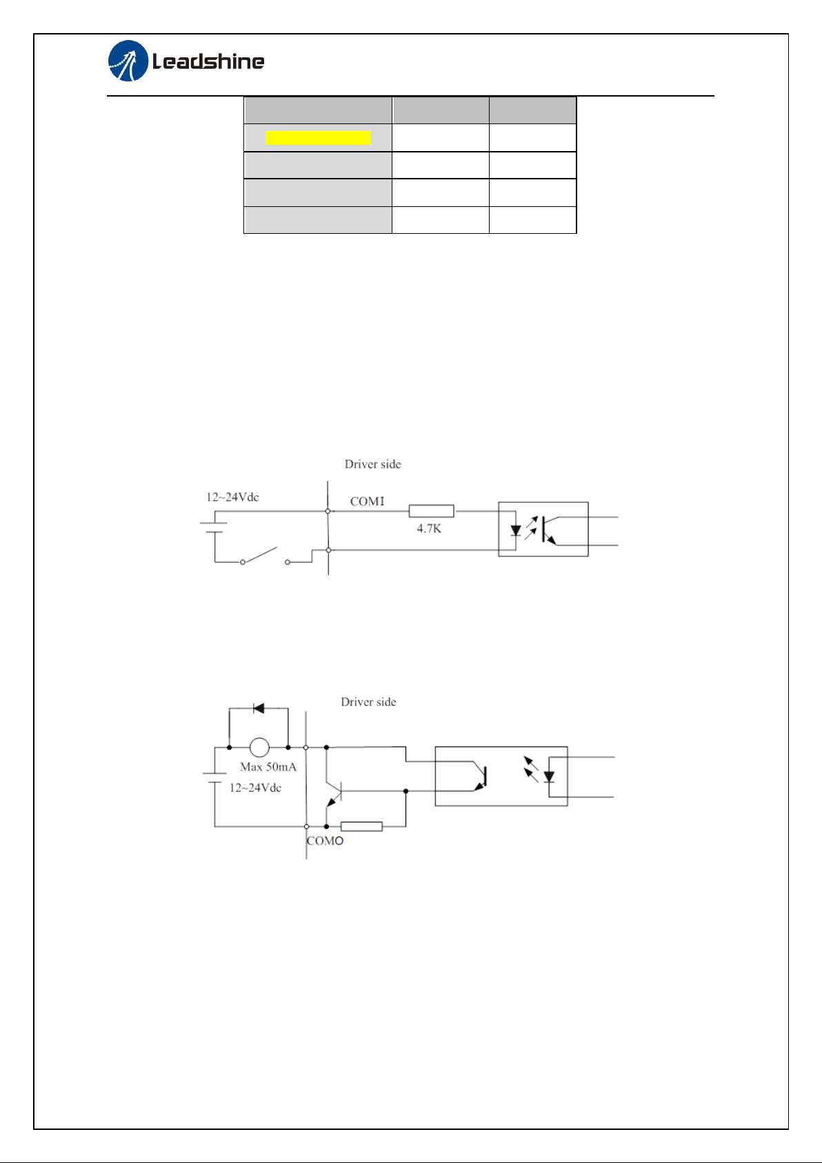
3.3 I/O InterfacePrinciple
3.3.1 Switch Input Interface
Figure 3-4 Switch Input Interface
⑴The user provide power supply, DC 12-24V, current≥100mA
⑵Notice: if current polar connect reversely, servo driver doesn’t run.
3.3.2 Switch Output Interface
Figure 3.5 Switch Output Interface
(1) The user provide the external power supply . However, if current polarity connects reversely, servo
driver is damaged.
(2) The output of the form is open-collector, the maximum voltage is 25V, and maximum current is
50mA. Therefore, the load of switch output signal must match the requirements. If you exceed the
requirements or output directly connected with the power supply, the servo drive is damaged.
(3) If the load is inductive loads relays, etc., there must be anti-parallel freewheeling diode across the
load. If the freewheeling diode is connected reversely, the servo drive is damaged.

18
ELD2-RS70** User Manual
3.3.3 Pulse Input Interface
270R
DIR+
DIR-
PUL+
PUL-
270R
Driver side
Figure 3-6 Pulse InputInterface Differential Drive Mode
Figure3-7 Pulse Input Interface SingleTerminal Drive Mode
(1) In order to transmit pulse data properly , we recommend using the differential drive mode.
(2) The differential drive mode,AM26LS31, MC3487 or similar RS422 line drive.
(3) Using of single-ended drive will cause reduction of the operation frequency.
(4) The user provide external power supply for single-ended drive. However, if current polarity
connect reversely, servo driver is damaged.
(5) The form of pulse input is the following form 3.7 below, while thearrows indicates the count .
Table 3.7 Pulse Input Form
Pulse command form
CCW
CW
Parameter setting value
Pulse symbol
PUL
DIR
Pulse + direction
The form of pulse input timing parameter is the following form 3.8 below. The 4 times pulse
frequency ≤ 500kH if 2-phase input form is used.
Table 3.8 the parameters ofpulse input time sequence
parameter
Differential drive input
Single-ended drive input
tck
>2μs
>5μs
th
>1μs
>2.5μs
tl
>1μs
>2.5μs
trh
<0.2μs
<0.3μs
trl
<0.2μs
<0.3μs
ts
>1μs
>2.5μs
tqck
>8μs
>10μs

19
ELD2-RS70** User Manual
tqh
>4μs
>5μs
tql
>4μs
>5μs
tqrh
<0.2μs
<0.3μs
tqrl
<0.2μs
<0.3μs
tqs
>1μs
>2.5μs
Figure 3.8 pulse+ direction input interface timing (the maximum of pulse frequency : 500KHZ)

20
ELD2-RS70** User Manual
Chapter 4 Parameter
4.1 ParameterList
Mode
Parameter Number
Name
P
S
T
Classify
Number
P
S
T
【Class 0】
Basic
setting
00
Model following control
01
control mode setup
P
S
T
02
real-time auto-gain tuning
P
S
T
03
selection of machine stiffness at real-time auto-gain tuning
P
S
T
04
Inertia ratio
P
06
command pulse rotational direction setup
P
07
command pulse input mode setup
08
Command pulse counts per revolution
P
09
1st numerator of electronic gear
P
10
denominator of electronic gear
P
S
T
11
output pulse counts per one motor revolution
P
S
T
12
reversal of pulse output logic
P
S
T
13
1st torque limit
P
14
position deviation excess setup
P
S
T
16
Regenerated discharge resistance value
P
S
T
17
Regenerative discharge resistance power
P
【Class 1】
Gain Adjust
00
1st gain of position loop
P
S
T
01
1st gain of velocity loop
P
S
T
02
1st time constant of velocity loop integration
P
S
T
03
1st filter of velocity detection
P
S
T
04
1st time constant of torque filter
P
05
2nd gain of position loop
P
S
T
06
2nd gain of velocity loop
P
S
T
07
2nd time constant of velocity loop integration
P
S
T
08
2nd filter of velocity detection
P
S
T
09
2nd time constant of torque filter
P
10
Velocity feed forward gain
P
11
Velocity feed forward filter
P
S
12
Torque feed forward gain
P
S
13
Torque feed forward filter
P
S
T
14
2nd gain setup
P
15
Control switching mode
P
17
Control switching level
P
18
Control switch hysteresis
P
19
Gain switching time
P
35
Positional command filter setup
P
S
T
36
Encoder feedback pulse digital filter setup
P
S
【Class 2】
Vibration
Restrain
Function
00
adaptive filter mode setup
P
S
T
01
1st notch frequency
P
S
T
02
1st notch width selection
P
S
T
03
1st notch depth selection
P
S
T
04
2nd notch frequency
P
S
T
05
2nd notch width selection
This manual suits for next models
4
Table of contents
Popular Power Tools manuals by other brands


Zico
Zico ZI-8065 operating instructions

Trotec
Trotec PTNS 10-20V Original instructions

Bosch
Bosch GWX 13-125 Original instructions

SPX
SPX ACCUTORQ 7375 operating instructions

Insta Graphic Systems
Insta Graphic Systems 718 Operation and maintenance manual

Power Craft
Power Craft STAR 88610 instruction manual


