manuals.online logo
Brands
  1. Home
  2. •
  3. Brands
  4. •
  5. Leadvision
  6. •
  7. Outdoor Furnishing
  8. •
  9. Leadvision WPC PERGOLA User manual

Leadvision WPC PERGOLA User manual

Option A
Option B
INSTALLATION INSTRUCTIONS
WPC PERGOLA
10’x10’
269mm/10.59”
269mm/10.59”
Base plate cover
3048mm/120’’
3048mm/120’’
3048mm/120’’
2052mm/80.76”
2454mm/96,6” 2454mm/96,6”
2835mm/111.6”
L1: U-clip X16
L2: M8 60mm screw bolt X16
L3: L-angle clip X105
L4: 4.2X25mm screw X270
L5: Expansion screw X16
L6: M10 treaded rod X12
L7: 3.8X25mm screw X40
Base plate cover X4
Drill
Straight line
Straight line
Mark line
The hole size
Mark point
Z=3537mm/139.2''
16
0.629
A:Steel inner post
According to the measurement, please put the steel inner post (A)
on the ground. ATTENTION: The ground should be flat.
STEP:1 STEP:2
Z
Z
198mm7.8’’ 198mm7.8’’
Between80-90mm
(3.15’’-3.55’’)
2501mm/98.4”
2501mm/98.4”
2105mm/82.8”
2105mm/82.8”
attention
Note:
Please drill the holes as
the diagram shown.
Drill the points
Straight line
Straight line
Straight line
Straight line
Put the posts on the expansion screws (L5)
Fix the expansion screws (L5)
L5 Note: Please be careful not to break the base
plate cover.
Put the B over the A. When touching th WPC
part, please wear gloves, in case there is oil
on the WPC posts.
Before fixing the posts to the ground, refer to the front page of the guide (option A or option B), using
the pre-drilled holes on the end of the posts, choose the orientation of the desired roof structure.
same
STEP:3 STEP:4
STEP:5
2
4
Straight line Straight line
same
Measure and adjust until the
following requirements.
Measure the distance between the
posts and the length is 2454mm/102”.
1.Use the Level to ensure the a side and b side of the
posts must be vertical to the ground.Please adjust if
necessary.
Use the wrench to fix the
expansion screws (L5)
2.The ground should be flat.
Straight line
Straight line
2454mm/102”
2454mm/102”
5
STEP:6
STEP:7
STEP:8
3
Straight line Straight line
Post Installation A & B
Put the base plate covers (H) on the WPC posts.
6
2454mm/102”
2454mm/102”
2454mm/102”
2454mm/102”
Measure again
B
STEP:9
STEP:1
7
Assemble the treaded rod (L6) and the U-Clips (L1) as the diagram shown.
STEP:2
Install the cross beams (C) with the treaded
rod (L6) and the U-clips (L1).
8 pieces 4 pieces
L6
L1
middle
top
bottom
Note: Please adjust the distance
between the posts according to
the holes position on the C.
8
L7
L7
L7
Note: Keep the screws (L7) parallel to the cross beam (C).
Keep Parallel
Keep Parallel
L7 L7
Please pre-drill the holes for the screws (L7) with
Φ4mm(Φ0.2”) and fix the screws (L7). Please do not
pre-drill the inner aluminum.
STEP:3
9
Note :The drain holes must
be downwards.
Install the beams 2 (F) to the cross beams (C) with the U-Clips (L1) and the screws bolt (L2).
Note: Please use the wrench to
fix the L2 go through the holes of
the F tightly.
Beam F installation
10
Note :The drain holes
must be downwards.
Pre-drill the holes on the beam 2 (F), please do not
pre-drill the inner aluminum.Fixing the U-Clips (L1)
and screws (L7) with the holes we pre-drill as the
diagram shown.
Use the wrench to install the
beam 3 (G) with the screws
bolt (L2) tightly.
Fix the beam 3 (G) according to the
6 cuts of the beam 1-2 (E).
L7 L7
L7
L7
Keep Parallel
Keep Parallel
Beam G installation
11
7
D
L4
L3
Fix the L-angle clips (L3) and the screws (L4) to the beams (D).
STEP:1
Fix the L-angle clips (L3) and the screws (L4) to the beams (D).
Put the beams (D) on the cross beams (C), one piece on each side.
Beam D installation
L4
Aluminium
The hole Φ5mm
WPC
Aluminium
WPC
12
STEP:2
STEP:3
Pre-drill the cross beams (C). ATTENTION: Do not pre-drill the inner aluminum.
Measure the distance of the cross beams (C) as the diagram shown which is 222mm/8.74” and mark the points.
222mm/8.74”222mm/8.74”
Fix the screws (L4) on the cross beams (C).
Adjust the distance between the two pieces of the beam 1-2 (E), the distance “P” is
269mm/10.59” and mark the points.
E×7
E
PPPPPPPP
8
STEP:1
There are 6 cuts on each pieces. Please adjust the cuts to fit onto the cross beams (C).
13
Beam (E)
L4
L3
Fix the L-angle clips (L3) and the screws (L4) to the beams (E).
Beam E installation
M M
N
Pre-dril the points on the WPC beam and do not
pre-drill the inner aluminum.
Fix the screws (L4) and measure again the distance as the Page 1 show.
STEP:2
STEP:3
Aluminium
The hole Φ5mm
WPC
Aluminium
WPC
L4
Fix the screws (L4) on the cross
beams (C).
14

Other Leadvision Outdoor Furnishing manuals

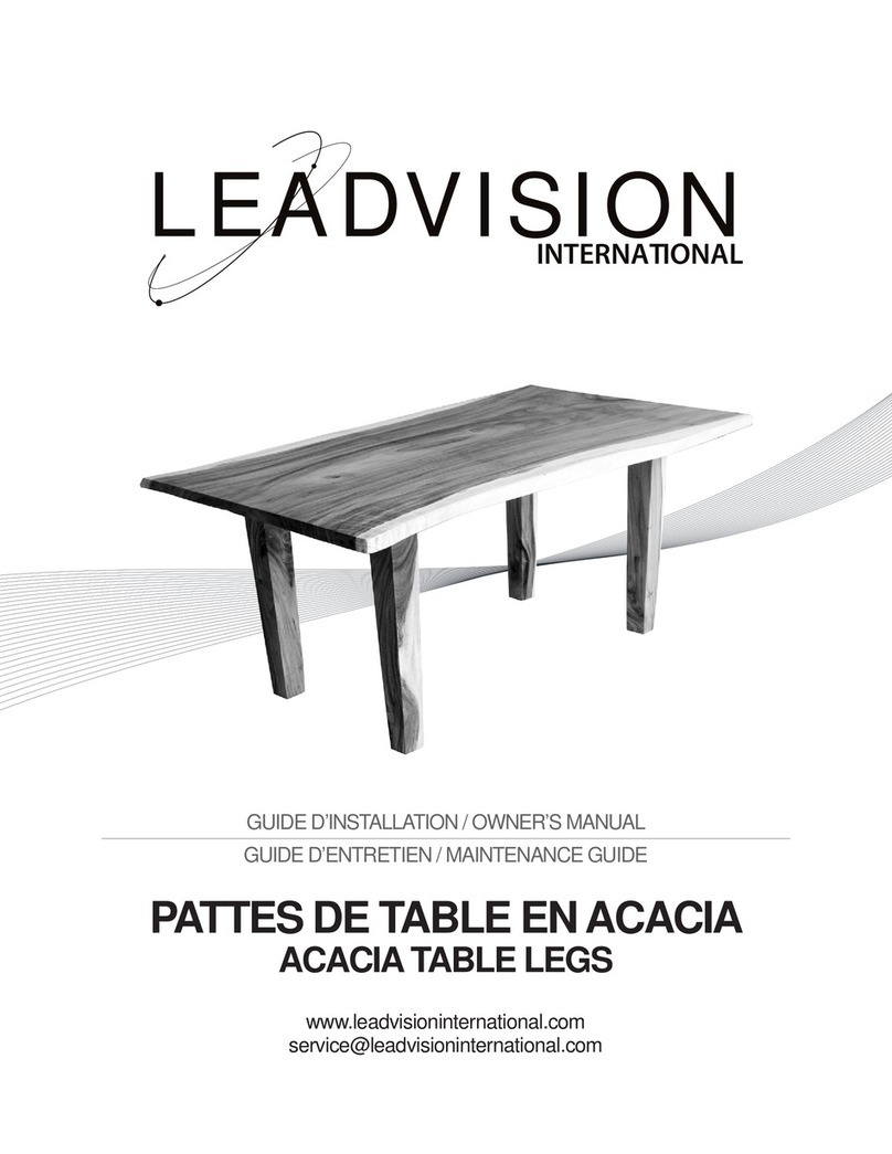
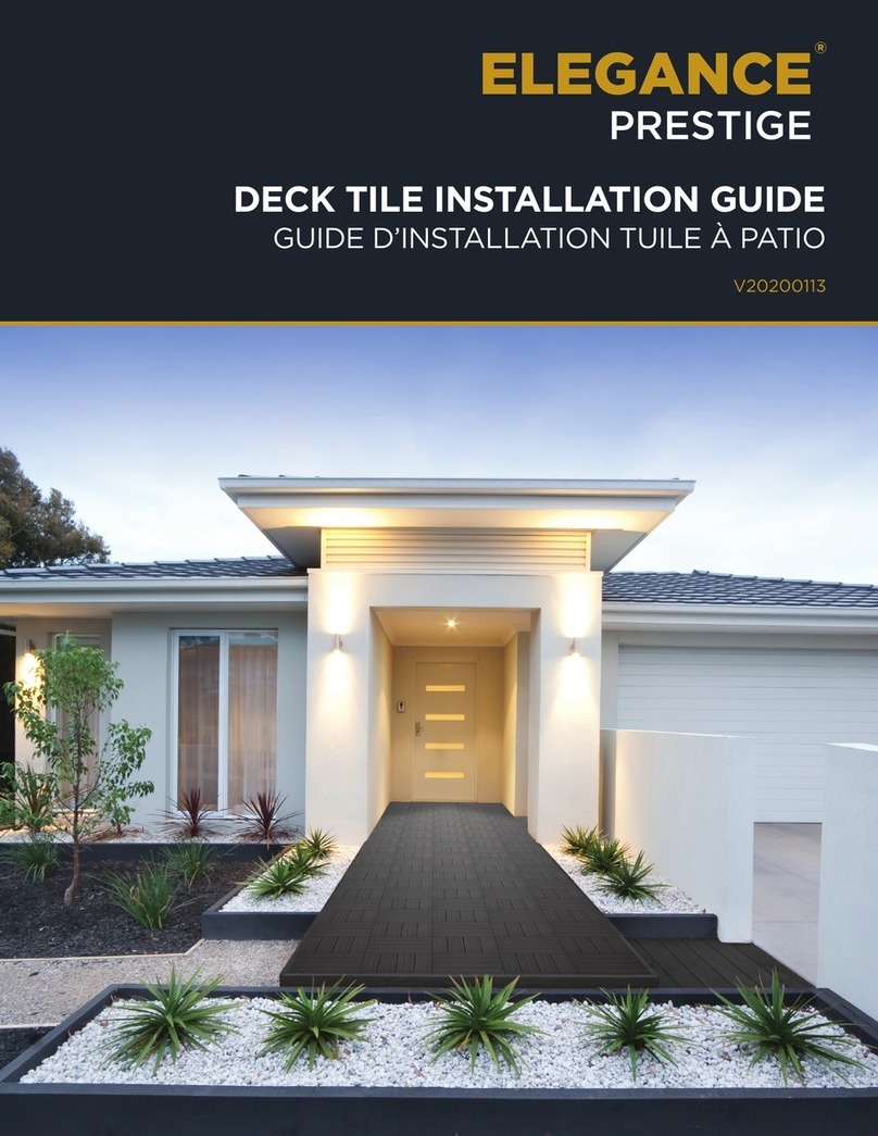
Leadvision ELEGANCE PRESTIGE User manual

Leadvision

Leadvision ELEGANCE PRESTIGE User manual

Leadvision ACACIA TABLE LEGS User manual

Leadvision

Leadvision ACACIA TABLE LEGS User manual

Popular Outdoor Furnishing manuals by other brands
TREX TX4513X Assembly instructions

TREX

TREX TX4513X Assembly instructions

Members Mark Heritage BGF05700-6FC Assembly instructions & user manual

Members Mark

Members Mark Heritage BGF05700-6FC Assembly instructions & user manual

Best Choice Products SKY5288 instruction manual

Best Choice Products

Best Choice Products SKY5288 instruction manual

Dura Trel Sunburst Trellis 11147/8 Assembly instructions

Dura Trel

Dura Trel Sunburst Trellis 11147/8 Assembly instructions

Polywood Chippendale CDD200 Assembly instructions

Polywood

Polywood Chippendale CDD200 Assembly instructions

Polywood 600 Series Assembly instructions

Polywood

Polywood 600 Series Assembly instructions

HAMPTON BAY BELCOURT D11334-LSR Use and care guide

HAMPTON BAY

HAMPTON BAY BELCOURT D11334-LSR Use and care guide

Polywood Chippendale CDG48 Assembly instructions

Polywood

Polywood Chippendale CDG48 Assembly instructions

Mercia Garden Products 01OVEABKSTR-V2 General instructions

Mercia Garden Products

Mercia Garden Products 01OVEABKSTR-V2 General instructions

Anova RCPTC6 Assembly instructions

Anova

Anova RCPTC6 Assembly instructions

PHI VILLA 5PCS TABLE & CHAIRS Assembly instructions & user manual

PHI VILLA

PHI VILLA 5PCS TABLE & CHAIRS Assembly instructions & user manual

PHI VILLA E02GS008 Use and care guide

PHI VILLA

PHI VILLA E02GS008 Use and care guide

Gainsborough K327 quick start guide

Gainsborough

Gainsborough K327 quick start guide

Rutland County Garden Furniture Screen Pergola Assembly instructions

Rutland County Garden Furniture

Rutland County Garden Furniture Screen Pergola Assembly instructions

Hanover HVNB48 quick start guide

Hanover

Hanover HVNB48 quick start guide

Palram CANOPIA SANREMO 10x18/3x5.46 How to assemble

Palram

Palram CANOPIA SANREMO 10x18/3x5.46 How to assemble

Courtyard Creations TGS38PB Assembly instructions

Courtyard Creations

Courtyard Creations TGS38PB Assembly instructions

Lakeland Mills Cedar Log Single Chair Porch Swing CF26 manual

Lakeland Mills

Lakeland Mills Cedar Log Single Chair Porch Swing CF26 manual

manuals.online logo
manuals.online logoBrands
  • About & Mission
  • Contact us
  • Privacy Policy
  • Terms and Conditions

Copyright 2025 Manuals.Online. All Rights Reserved.