2 3
Installation Overview:
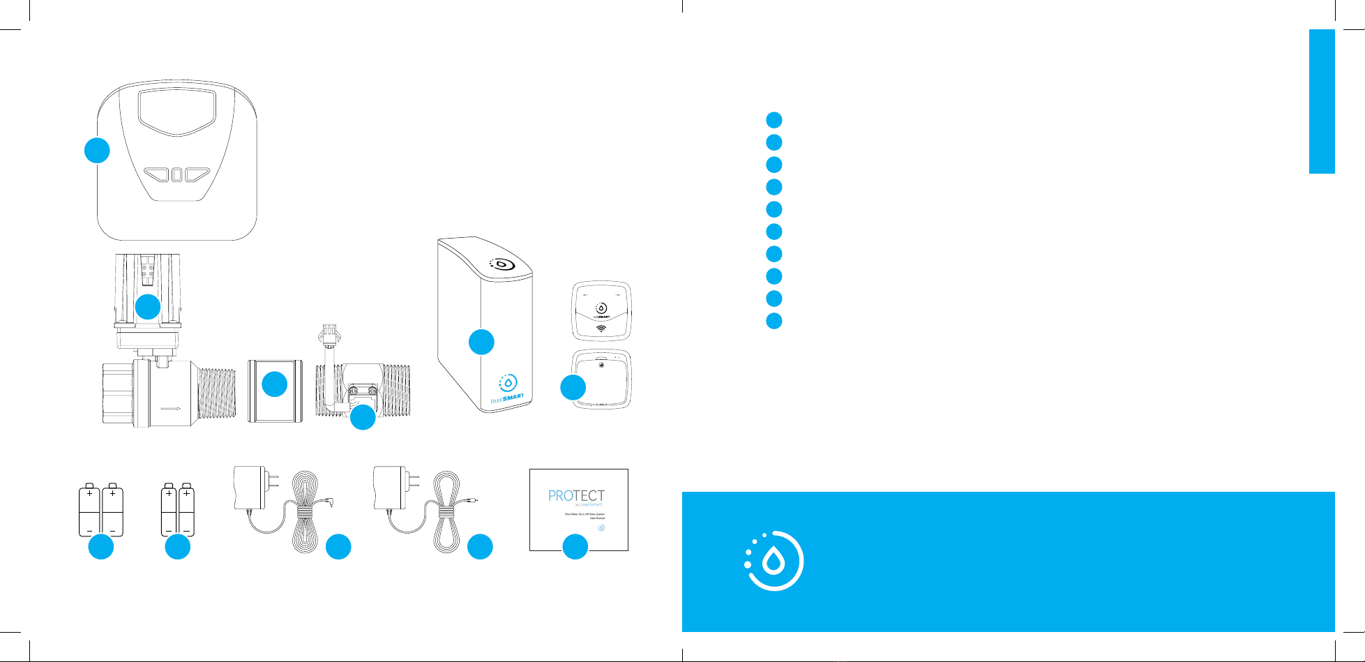
In the Box.................................................................................................................................. 4
Setup Requirements.............................................................................................................6
Important Installation Information................................................................................7
Section I:
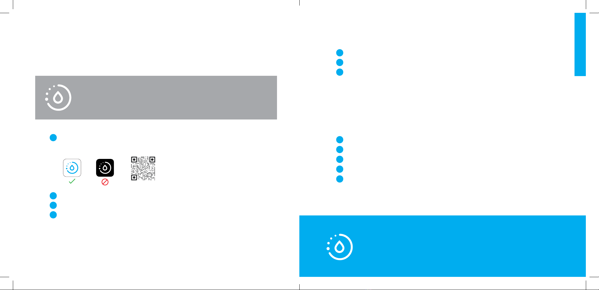
LeakSmart Hub 3.0 Pre-Installation Customer Setup
Requirements...........................................................................................................................9
Section II:
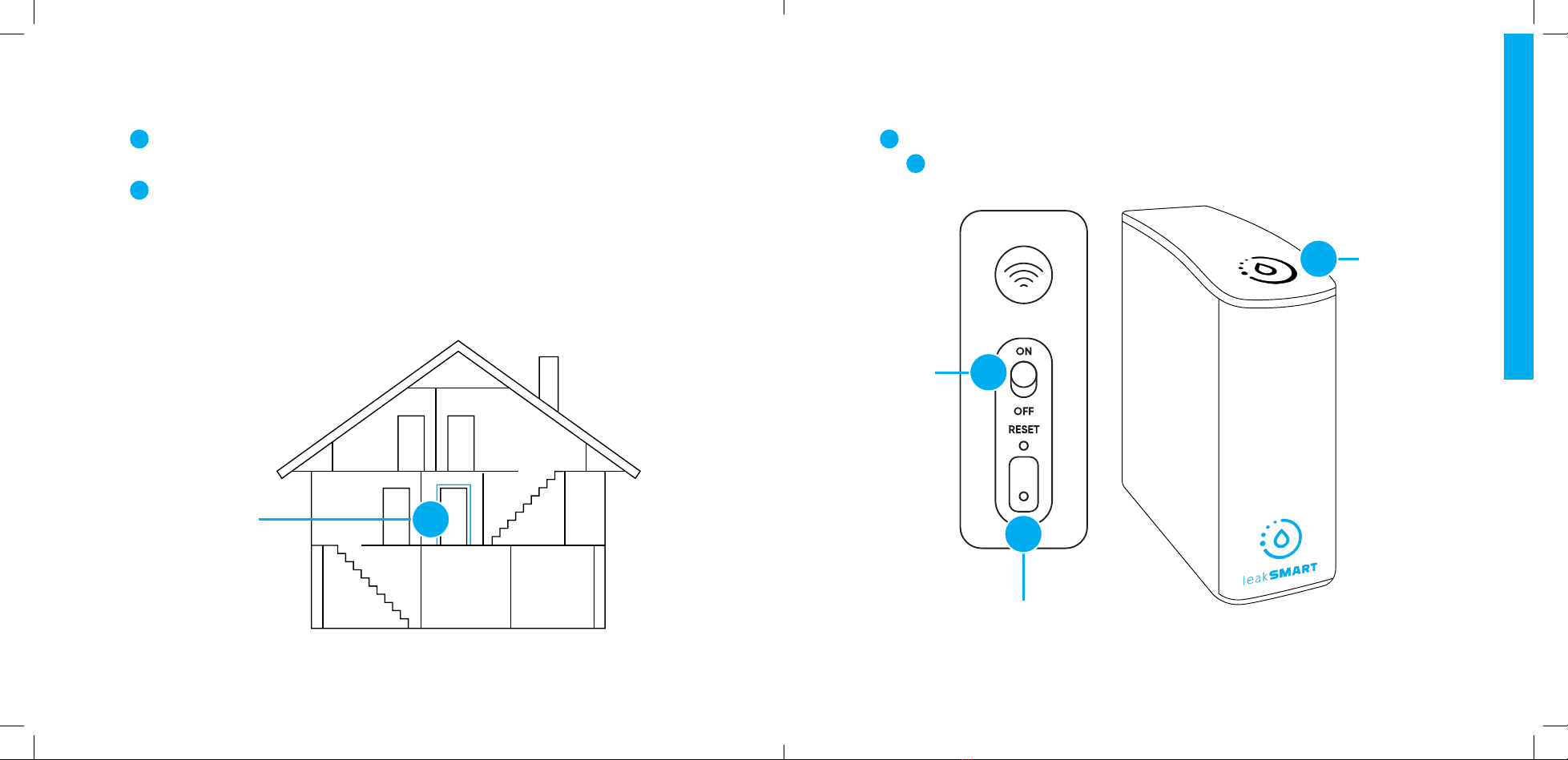
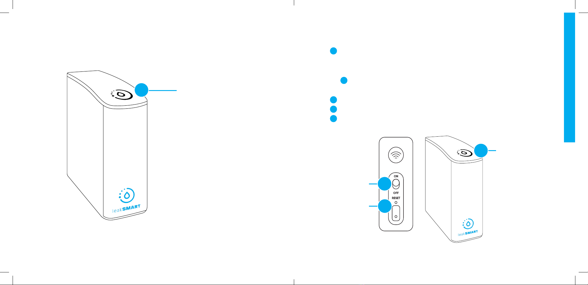
LeakSmart Hub 3.0 Installation.....................................................................................10
Connect the Hub to the Home Wi-Fi Network.....................................................12
Performing a Factory Reset............................................................................................15
Protect by LeakSmart Setup..........................................................................................16
Pair the Protect by LeakSmart to the Hub 3.0.......................................................18
Test Local and Remote Control of the Valve Control Head..........................20
Table of Contents Table of Contents
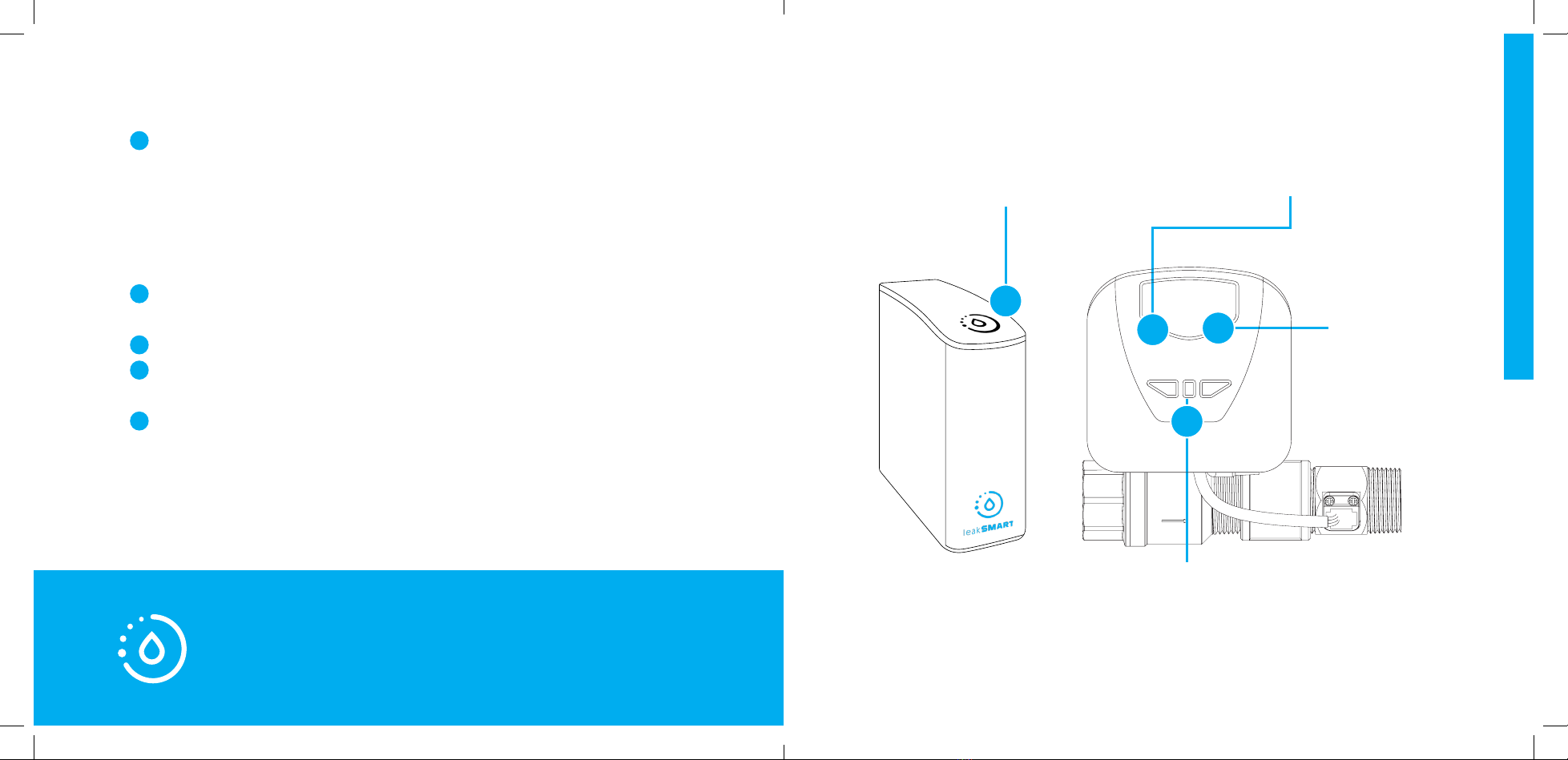
Section III:
Protect by LeakSmart Flow Meter Shut-O Valve Installation ...................22
Pre-Installation Assembly................................................................................................22
Installation Assembly.........................................................................................................24
Protect by LeakSmart Validation................................................................................30
Section IV:
Sensor Setup and Operation........................................................................................32
Temperature & Humidity Settings & Alerts..............................................................36
Protect/Detect Settings & Alerts.................................................................................37
Alert Setup..............................................................................................................................38
Adding Alert Contacts......................................................................................................38
Test Leak Simulation..........................................................................................................39
Clearing Test Leaks............................................................................................................39
Y88501PM Protect Shutoff vlv Manual_REV 9.2021.indd 2-3Y88501PM Protect Shutoff vlv Manual_REV 9.2021.indd 2-3 9/2/21 10:19 AM9/2/21 10:19 AM