LEAP Electronics SU-56A User manual

SU-56A User Manual
SU-56A Gang Programmer
User Manual
-1-

SU-56A User Manual
Catalogue
Chapter 1. Product introduction.................................................3
Chapter 2. Precautions for use...................................................4
Chapter 3. Precautions for accessories..................................6
3.1. Driver board installation................................................6
3.2. Socket board installation..............................................7
Chapter 4. Description of hardware and appearance........
4.1. Power...................................................................................
4.2. USB......................................................................................
4.3. Start button........................................................................
4.4. Power LED.........................................................................
4.5. LED on socket board.....................................................9
Chapter 5. PC software operating instructions..................10
5.1. Software Installation....................................................10
5.2. Drive Installation...........................................................10
5.3. Gang programming software interface
(Home screen).................................................................11
5.4. Programming description...........................................12
5.5. Gang programming software interface
(Project management).................................................13
5.6. Gang programming software interface
(Option)............................................................................14
5.6.1. Log Setting............................................................14
5.6.2. Self Test.................................................................15
5.6.3. Information............................................................16
5.6.4. BIOS Update........................................................17
5.6.5. Auto Run................................................................1
5.6.6. SD Card.................................................................19
5.6.7. HDCP.......................................................................20
5.6. . SSD.........................................................................21
5.6.9. PinScan Delay......................................................22
5.6.10. DateTime Setting..............................................23
Chapter 6. Simple steps to operate the software..............24
-2-

SU-56A User Manual
Chapter 1. Product introduction
SU-56A integrates programming with existing machine
architecture. In addition to quickly supporting existing
programming components (by transferring or modifying PCB), it
can also create dedicated module boards for specific
components to achieve diversity of support.
In addition to the replaceable socket board of this machine,
the driver board underneath can also be replaced. When
supporting certain IC device with more special and complex
designs, the driver board can be replaced to achieve the
purpose of support. To save the complexity in the design of the
socket adapter (which can reduce the cost of replacement).
This type of programmer can use single-site software to
connect and programming data to a single IC to perform more
complex parameter settings, and then package it into a project
after confirmation.
During gang programming, you can also open the gang
programming software with a simpler interface and load the
project into it, so that you can flash multiple ICs at the same
time for gang programming. This software does not have
complicated operating procedures, and it cannot change the
relevant settings of the project. , which can minimize the risk of
gang programming.
(The following is only a functional descri tion of the gang
rogramming software.For single-site rogramming
software, lease refer to the documentation of Universal IC
Writer II.)
-3-

SU-56A User Manual
Chapter 2. Precautions for use
All operations, maintenance, and repair
services must observe the following safety
precautions and safety warnings.
Our com any is not res onsible for any losses or liability
by misusing the instrument without following the
recautions in this manual cause the un redictable
henomena.
2.1. When replacing the Socket/Driver module board, please turn
off the power of the product in advance, carefully remove the
original module, and then install the new module board. When
installing, pay attention to the direction and align the pin holders
before installing. If there is excessive resistance during
installation, please recheck whether there is any wrong
direction or tilted. You can restart the programmer only after
confirming that everything is correct.
2.2. The Socket board is a consumables. Factors such as the
number of times the IC is picked up and placed, the operating
habits of the personnel, the cleanliness of the IC pin surface,
whether the IC package meets standard tolerances, etc., will all
affect the contact quality between the socket and the IC. When
you find that the failure rate of a certain socket board has
increased significantly, but there is no obvious improvement
after cleaning the socket, you may need to consider to replace
it.
2.3. The programmer will provide power to the module board
when programming IC. If the IC is placed in the wrong position
or the wrong number is selected, the programmed IC may be
damaged.
2.4. If the device to be programmed is OTP (one-time
programming) or the device has OTP parameter settings,
please take a special care to them because the device (or
parameters) can only be programmed once and cannot be
restored through the clear function afterwards.
2.5. IC information, batch numbers, programming processes and
-4-

SU-56A User Manual
operating software changing oftenly, so please pay attention to
whether data file in master IC, the parameters setting,
processes and software version are completely correct when
you're operating.
2.6. When a new work order or a new IC comes online for the first
time every day, the ICs burned in the first round must be verified
first to avoid errors in the master IC, files, machines or
operating software, resulting in poor programming. cause
unnecessary losses. During gang IC programming, it is
necessary to verify and check whether the programmed IC is
normal several times, including the setting of software, device
parameter, device security protection, specific area settings,
bad block (NAND Flash) and other settings.
2.7. Machine operators must be trained and designated
personnel. Do not allow untrained personnel to operate the
machine.
2. . Self-repair is prohibited without the consent of our company
during the warranty.
2.9. If you find any programming problems that can't be solved,
please suspend use.
2.10. It's our pleasure to help you solving programming issue, but
please follow the operation statement above.
Our com any will not be res onsible for any losses caused
by machine failure, IC damage, or incorrect data burning
caused by any o eration that violates the stated matters.
-5-
SU-56A User Manual
Chapter 3. Precautions for accessories
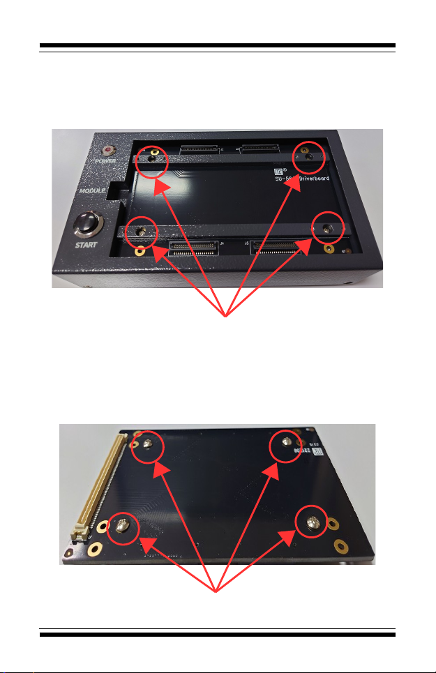
3.1. Driver board installation
3.1.1. The Driver board is fixed by 4 screws. Please remove
the screws before removing the driver board. Then pull up
the driver board from left side(Tool required).
Please loose the four screws in the support bar before remove the diver
board
3.1.2. When assembling a new driver board, please first
check whether there are mechanical components for
locking and supporting at the top,If not, the PCB may be
deformed and damaged due to excessive extrusion during
use.
Please loose the four screws in the support bar before remove the diver
board
Driver board and supporting mechanism screw locations
-6-
SU-56A User Manual
3.1.3. When installing, just lay it flat, align the pins on driver
board with the pins on the programmer of the machine and
press down.Make sure there is no problem with the
combination and then tighten the screws
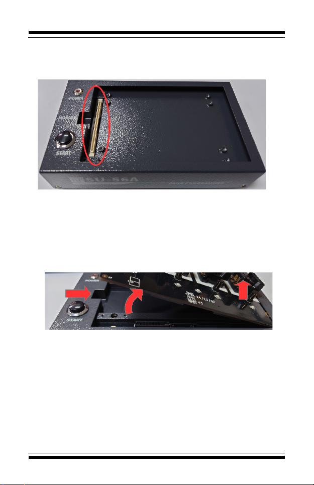
3.2. Socket board installation
3.2.1. When you want to remove the socket board, we
suggest that lift the left side of it to the right( Please notice
the angle should not be too large, otherwise the pins may
be damaged), then pull up the right side directly.
3.2.2.
The steps to remove: first lift the left side, then lift the right side
3.2.3. To install a new socket board, just align it and press it
down.
-7-
SU-56A User Manual
Chapter 4. Description of hardware and appearance
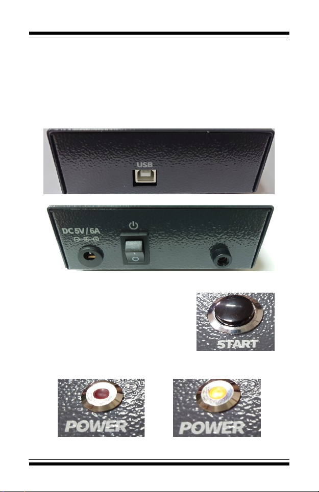
4.1. Power
4.1.1. Use a 5V DC power supply (DC, positive inside and
negative outside). Wrong voltage and polarity may cause
damage to the machine.
4.2. USB
4.2.1. USB type B connect to PC
4.3. Start button
4.3.1. The function is as same as
the start button in the software.
Press it to start programming.
4.3.2. It only works after loading the
project file.
4.4. Power LED
4.4.1. When it's light up mean power on.
Power OFF Power ON
-8-
SU-56A User Manual
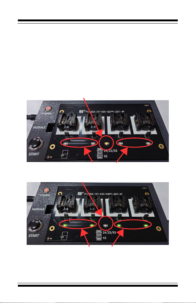
4.5. LED on socket board
4.5.1. WORK LED:Usually only 1 on the board, yellow color.
It will light up during the programming and light off after the
programming.
4.5.2. PASS LED:The number will as same as the socket.
4.5.2.1. Light up:Programming Pass.
4.5.2.2. Flash:Programming Fail.
4.5.2.3. Light off:The IC is not putted on or the IC has
been removed after programming. 。
The work LED will light up during the programming
The pass LED will light off during the programming
The work LED will light off after the programming
The pass LED will light up or flash after the programming
-9-
SU-56A User Manual
Chapter 5. PC software operating instructions
5.1. Software installation
5.1.1. Install the Universal IC Writer II software.
5.1.2. Install the SU-56 software (For gang programming)
5.1.3. Install the DataBase.
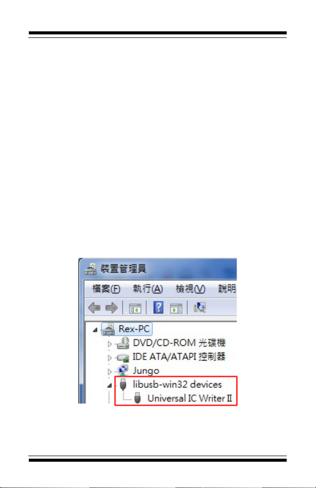
5.2. Driver installation
5.2.1. Before the installation, please connect the USB cabe
and power cable first, then turn on the power.
5.2.2. The Device manager will shows a USB device when
you connect the programmer with PC(You can connect
multiple programmers).You need to install the driver if it's
the first time connection. Please choose the file path as
same as your software and select the file"USBDrv"
(Windows will automatically search for the appropriate
version of driver)
5.2.3. After the installation, the name will become'Universal
IC Writer II'(The number of devices here would be as same
as the units you connect to PC)
-10-

SU-56A User Manual
5.3. Gang programming software interface
(Home screen)
5.3.1. ”Project Manage” & ”System setting”.For detailed
instructions, please refer to Chapters 5.5 and 5.6
5.3.2. Record the current programming result. Press [>>0] to
reset the count value to zero.
5.3.3. Programming Button
5.3.3.1. START:Start programming. It also can start by
pressing the button on the programmer
5.3.3.2. END:The order will end when you click
it(Saving Log at the same time) but it will wait for the IC
which is programming.
5.3.3.3. AutoRun:When this function is turn on, As long
as the socket is filled up with the IC, it will automatically
start programming.
5.3.4. Display the information of the project file you loaded.
5.3.5. Record all the detailed information of each action,
process and result.
5.3.6. Chip status in the socket board of every programmer
-11-
5.3.1
5.3.2
5.3.3
5.3.4
5.3.5
5.3.6

SU-56A User Manual
5.4. Programming description
The following explains the meaning of the screen (status)
during programming.
5.4.1. WORKING:Now programming
5.4.2. PASS:Programming succeed.
5.4.3. FAIL:Programming failed.
5.4.4. PUT UP:Waiting for the chip to be removed
5.4.5. READY:Chip is placed. Waiting for programming.
-12-

SU-56A User Manual
5.5. Gang programming software interface
(Project management)
5.5.1. The page that manage the programming project file.
5.5.2. Description of each button
5.5.2.1. Add:Add the project file into the programmer.It
will ask updating the socket board and SSD data when
it's necessary(Only for eMMC chips)
5.5.2.2. Delete:Delete the selected project.
5.5.2.3. Load:Load the selected project. After
successful loading, the page will be closed and returned
to the home screen.
5.5.2.4. Option:Switch to "System Options Settings"
(Please refer to Chapter 4.9).
5.5.3. When checked, the project file added (Add) will directly
use the internal Database file. If not checked, the file on the
hard disk will be used.
5.5.4. When adding project by check will clear all the original
projects here
5.5.5. Showing the information you selected.
-13-
5.5.2
5.5.3 5.5.4
5.5.5

SU-56A User Manual
5.6. Gang programming software interface
(Option)
5.6.1. Log Setting
5.6.1.1. Message Box Clearing Selection
Setting auto clearing or saving "Log" in the home
screen.
Auto Clear:Clear the Log when the set number of rows
is exceeded.
Auto Clear and Save:Save before Clear the Log when
the set number of rows is exceeded.
Order's over (press END) would auto save Log before
clear at that moment.
5.6.1.2. Limitation of The Number of Rows for Message
Set the home screen "Log" to be automatically cleared
when it exceeds the set number of lines.。
5.6.1.3. Select Log Save Directory
File path of saving "Log" in the home screen.
-14-
5.6.1.1
5.6.1.2
5.6.1.3

SU-56A User Manual
5.6.2. Self Test
5.6.2.1. Self Test for the programmer itself. Click
"Execute" to start testing the checked programmers and
show the result on the Display field.
5.6.2.2. The Display field will only show the results of
one unit. If you want to see the results of different units,
you must click the other programmer on the list.。
5.6.2.3. The socket board can't be installed during
the testing. The driver board is also limited to
general version. All others must be dismantled,
otherwise it will affect the test results or even
damage the rogrammer itself.
5.6.2.4. Led Flash has no effect here.
-15-
5.6.2.1
5.6.2.2

SU-56A User Manual
5.6.3. Information
5.6.3.1. Click "Execute" to show the informations of BIOS
Number, Version, Serial Number and socket board.
5.6.3.2. LP Display shows the result of only 1
programme. You need to choose other programmer
manually to see the result of others.
5.6.3.3. Socket Board field shows the socket board name
and the number of times it has been programmed
-16-
5.6.3.1
5.6.3.2
5.6.3.3

SU-56A User Manual
5.6.4. BIOS Update
5.6.4.1. The page that update the BIOS of the
programmer. Update the checked programmers by
clicking “Execute”
5.6.4.2. LP Display shows the current BIOS version of
Database.
5.6.4.3. The programmer will auto restart when the
update is done. The software will show that the
programmer is not detected.You need to back to home
screen and click"Project" to reconnect.
-17-
5.6.4.2
5.6.4.1

SU-56A User Manual
5.6.5. Auto Run
5.6.5.1. Setting the interval time of Auto Run
(Delay time from placing IC to starting programming)
-18-

SU-56A User Manual
5.6.6. SD Card
5.6.6.1. Clear all data in the SD Card of the selected
programmer by clicking "Quick Format" button
5.6.6.2. The Project list in the Project page will be
cleared when it execute
5.6.6.3. The data in the SSD of eMMC socket board will
not be cleared.
-19-
5.6.6.1
SU-56A User Manual
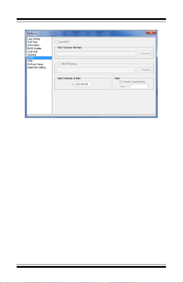
5.6.7. HDCP
5.6.7.1. Parameter settings for programming HDCP
files。
(Subject to the project which is executed by
click”Add/Load”in the Project page)
5.6.7.2. This page is for display only, please do the
settings on the Universal IC Writer II software.
5.6.7.3. This function currently does not su ort
eMMC rojects.
-20-
Table of contents
Other LEAP Electronics Motherboard manuals


