6.1 Always read instructions fully
before use.
6.2 Users should not be left unattended at
any time whilst using Leckey equipment.
6.3 Only use Leckey approved
components with your product. Never
modify the product in any way. Failure
to follow instructions may put the user
or carer at risk and will invalidate the
warranty on the product.
6.4 If in any doubt to the continued
safe use of your product or if any parts
should fail, please cease using the
product and contact our customer
services department or local dealer
as soon as possible.
6.5 Carry out all positional adjustments
and ensure that they are securely
fastened before you put the user into this
product. Some adjustments may require
the use of a tool which is provided with
each product. Keep all tools out of reach
of children.
6.6 When placing the user into the
standing frame, for safety reasons,
always secure the user’s feet and the
chest straps first. Then the hip and knee
straps should be fastened.
6.7 When used in the supine position it
is important to ensure the knee pad is
fastened securely. Always check the
clips are fully engaged.
6.8 Although the stander is fitted with
casters it is not a mobility device.
Always ensure that the castor brakes be
locked at all times when the frame is in
use, being adjusted or even just stored.
6.9 When adjusting the angle of the
Leckey Prone/Supine Stander ensure that
the user and all parts of the product are
well clear of surrounding furnishings to
avoid potential collisions.
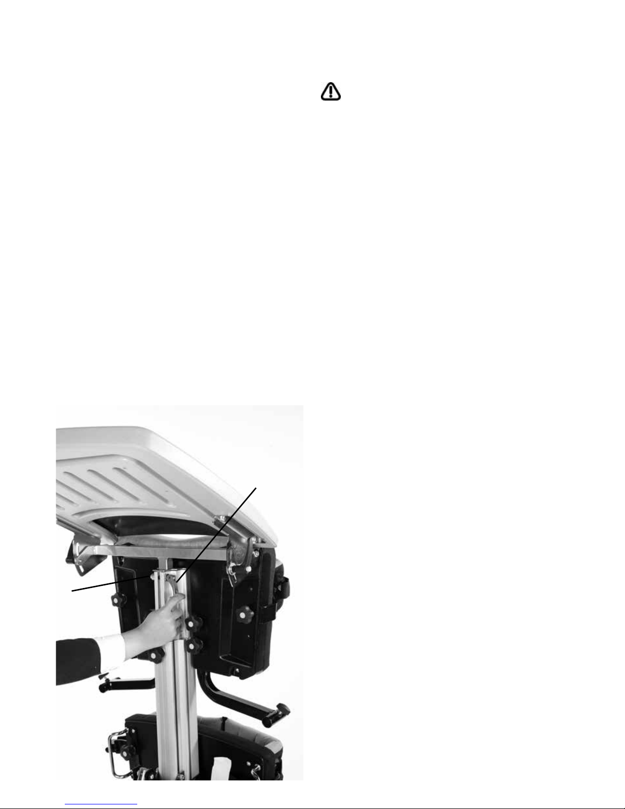
6.10 It is not recommended to adjust the
height of the back pad whilst the frame is
in use and in vertical position. Other fine
positional adjustments may be carried
out safely when the user is in the frame.
It is important to support all pads
when adjusting them while the user is
in the product.
6.11 Never leave the product on a
sloping surface, greater than 5 degrees.
Always remember to lock all the castors.
6.12 The product contains components
which could present a choking hazard to
small children. Always check that locking
knobs and bolts within the child’s reach
are tightened and secure at all times.
6.13 Leckey products comply with fire
safety regulations in accordance with
EN12182. However the product contains
plastic components and therefore
should be kept away from all direct
sources of heat including naked flames,
cigarettes, electric and gas heaters.
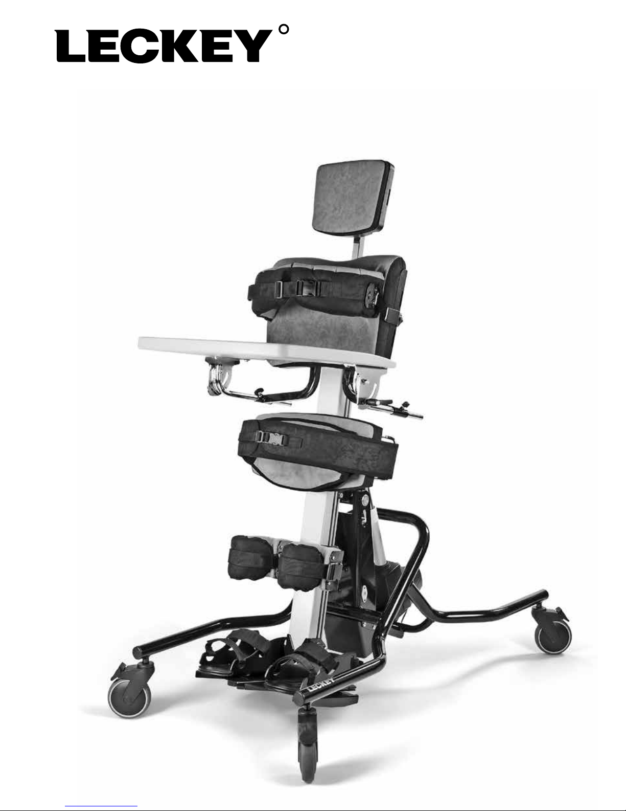
6 Safety information