Leckey MyWay User manual

My independence.
My freedom.
My choice.
My movement.
MyWay!
User Manual

p.2 MyWay User Manual
If you have ordered any
of the optional accessories,
these will also be included
in the box. Optional
accessories include:
•Saddle
•User Handles
•Ankle Guides
•Headrest
•Adult Connection Belt
(Patent No. GB2541697)
•Adult Handles
•Hoisting Straps
Your new Leckey
MyWay is here!
MyWay is an upright mobility device that supports children,
who cannot stand or walk independently, in an upright
position. When supported in the product, the wheeled frame
allows children to propel themselves about their environment
using their lower limbs. This manual shows you how you
can quickly and easily make use of all of MyWay’s functions.
The instructions on the safety and maintenance of the
product will ensure that you will enjoy the use of this
product for a long time.
The Leckey MyWay comes partially assembled and
your box should contain the following as standard:
Frame (including 4 castors)
Upper Support Unit
Harness in your chosen size
(Patent No. GB2542922)

p.3 MyWay User Manual
Contents
1. Intended Use p.04
2. Declaration of Conformity p.04
3. Terms of Warranty p.05
4. Product History Record p.05
5. Product Training Record p.05
6. Safety p.06
7. Contra-indications / Cautions p.07
8. Main Frame Set-Up / Features p.08
9. Harness Set-Up / Features p.18
10. Accessories Set-Up / Features p.28
11. Typical Set-Up Order p.36
12. Cleaning and Care Information p.38
13. Daily Product Inspection p.39
14. Annual Product Inspection p.40
15. Reissuing Leckey Products p.41
16. Product Servicing p.41
17. Technical Information p.42
18. Product and Accessory Codes p.43
Please read the following
guidance and instructions
fully before using
the Leckey MyWay.
Please also refer to
these instructions before
making any adjustments
to the device.
Failure to follow these
user instructions may
put the user at risk.
Please note, these instructions have been written according to the different product
components- the main frame set-up/features, the harness set-up/features and accessories
set-up/features. They have not been written in a specic set-up/adjustment order as this
will depend on the individual user. Please read these instructions to familiarise yourself
with the product features and then refer to section 11 for a guide to a typical set-up order.

p.4 MyWay User Manual
2.0 Declaration of Conformity
James Leckey Design Ltd as manufacturer with sole responsibility declares that the Leckey
MyWay conforms to the requirements of the 93/42/EEC Guidelines, Medical Device Regulations
2002 and EN 12182 Technical aids for disabled persons and test methods.
1.0 Intended Use
• MyWay is an upright
mobility device that
supports children, who
cannot stand or walk
independently, in an
upright position and allows
them to move about their
environment.
• MyWay is intended for use
by children already using a
supportive walking device;
children with Cerebral
Palsy in GMFCS levels III-
IV; children with Cerebral
Palsy in GMFCS level V who
have sufcient range of
movement in their lower
limbs to enable passive/
active stepping; and
children with a physical
disability which prevents
them from independent
upright mobility.
• The MyWay Size 1 frame
is suitable for users up to
25kg and a shoulder height
of 920mm; the Size 2
frame is suitable for users
up to 50kg and a shoulder
height of 1190mm; and
the Size 3 frame is suitable
for users up to 80kg and
a shoulder height of
1490mm.
Please see section
‘7.0 Contra-indications/
Cautions’ for further
information.

p.5 MyWay User Manual
4.0 Product History Record
Your Leckey product is classied as a Class 1 Medical Device and as such should only be pre-
scribed, set up or reissued by a technically competent person who has been trained in the use
of this product. Leckey recommend that a written record is maintained to provide details of all
set ups, reissue inspections and annual inspections of this product.
5.0 Product Training Records
(Parents, Teachers & Carers)
Your Leckey product is classied as a Class 1 Medical Device and as such Leckey recommend
that parents, teachers and carers using the equipment should be made aware of the following
sections of this user manual by a technically competent person:
3.0 Terms of Warranty
The warranty applies only when the product is used according to the specied conditions
and for the intended purposes, following all manufacturers’ recommendations (also see gen-
eral terms of sales, delivery and payment). A three year warranty is provided on all
Leckey manufactured products and components.
6.0 Safety
7.0 Contra-indications / Cautions
8.0 Main Frame Set-Up / Features
9.0 Harness Set-Up / Features
10.0 Accessories Set-Up / Features
11.0 Typical Set-Up Order
12.0 Cleaning and Care Information
13.0 Daily Product Inspection
Leckey recommend that a written record is maintained of all
those who have been trained in the correct use of this product.

p.6 MyWay User Manual
6.0 Safety
• Always read user
instructions fully
before use.
• Users should not be
left unattended at
any time whilst using
Leckey equipment.
• Only use Leckey approved
components with your
product. Never modify the
product in any way. Failure
to follow instructions may
put the user or carer at
risk and will invalidate the
warranty on the product.
• If in any doubt to the
continued safe use of your
product or if any parts
should fail, please cease
using the product and
contact our Customer Care
Team or your local dealer
as soon as possible.
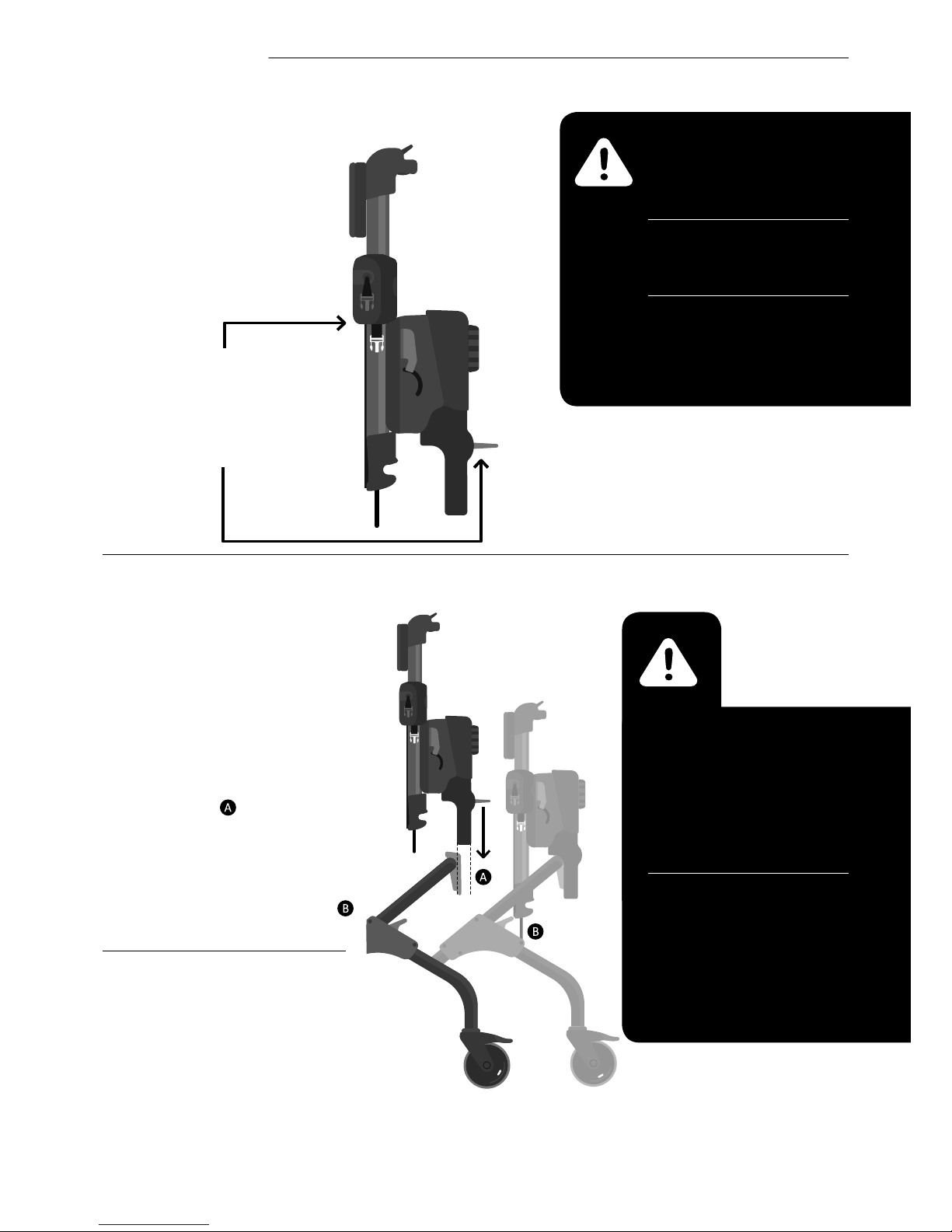
• Carry out all relevant
positional adjustments
and ensure that they are
securely fastened before
you put the user into
this product.
• Never leave the product
on a sloping surface,
greater than 5 degrees.
Always remember to lock
all the castors.
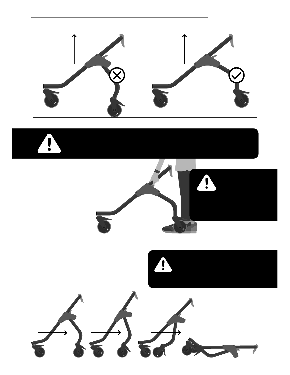
• Only hold onto the frame
or use the adult handles
accessory to steer and
move the product from
one area to another. Never
use the upper support unit
or any accessory for this
purpose.
• The product contains
components which could
present a choking hazard
to small children. Always
check that locking knobs
and bolts within the user’s
reach are tightened and
secure at all times.
• Clean the product
regularly. Do not use
abrasive cleaners. Carry
out maintenance checks
on a regular basis to
ensure your product is in
good working condition.
• Check all weight bearing
components are fully
secured before removing
manual/hoisting support
i.e. saddle, buckles/cords
attaching harness to frame
and shoulder straps.
• The white buckles must be
secured rst and opened
last during set up and exit
from the device. The white
buckles take the child’s
weight if they are not
bearing weight through
their legs.
• If the groin straps have
not been tted securely,
the child may slide down
a little within the harness.
If this results in the
harness digging into
the child’s armpits, then
the harness needs to be
reapplied more securely.
The saddle provides
additional support if
required.
• If hoisting the child from
the device, ensure the
groin straps are secured.
• Failure to follow the user
instructions may put the
child at risk.
• The product should be
stored carefully and not
used if any parts are faulty.
• Communicate with the child
regarding any positional
adjustments to be carried
out while the child is
supported in the device.
• Leckey products comply
with re safety regulations
in accordance with
EN12182. However the
product contains plastic
components and therefore
should be kept away from
all direct sources of heat
including naked ames,
cigarettes, electric and
gas heaters.
• The product is designed
for indoor and outdoor use
on smooth, level surfaces.
The product is not suitable
for use on uneven or rough
terrain. When not in use,
the product should be
stored in a dry place that is
not subjected to extremes
of temperature. The safe
operating temperature
range of the product is
+5° to +40° Celsius.

p.7 MyWay User Manual
7.0 Contra-indications/Cautions
Contra-indications
• Children with signicant
leg length discrepancy
which precludes from
reciprocal contact with
the oor when stepping.
• Children with a history
of frequent fractures
(e.g. Brittle Bone disease).
• Children using a
portable ventilator.
• Open/healing wounds
under areas of pressure
including trunk, groin
and shoulders.
• Spina Bida with protruding
lesion along spine.
• Children experiencing
discomfort associated
with positioning in or out
of the device where this
cannot be resolved with
adjustment of support/
positioning.
• Children with signicant
asymmetry of lower limbs
which precludes stepping.
• Children with no muscle
activity/movement of their
lower limbs.
Cautions
• Children with severe
dystonic movement
which presents a manual
handling risk for child and
carer when getting the
child in and out of the
product.
• Children with device fed
through the abdominal
wall, such as PEG and
gastrostomy.
• Children with abdominal
device in situ such as
Baclofen pump.
• Children with compromised
respiratory function, who
may experience increased
effort of breathing due to
t of harness.
• Children with severe
lower limb deformity
with reduced range of
movement to achieve
stepping.
• Using the product for
children with signicant
learning disability or
behavioural issues which
present risk of injury to
the child and/or carer.

p.8 MyWay User Manual
8.0 Main Frame Set-Up/Features
8.1 Frame | Unfolding the Frame
• Lift the frame out of the box and set it on a
at, stable surface, keeping it in the same
position as it was packaged within the box
i.e. as per image below.
• Stand at the base of the frame’s
‘U’ shape. Pull both triggers.
• Walk the frame’s front legs forward,
away from you (in direction of arrows),
engaging the front castors until the legs
are fully extended. Release both triggers.
Warning – when lifting the
frame, adhere to normal
moving and handling
procedures.
Warning – ngers should
be placed on triggers as
shown, to avoid potential
for nger nipping.
Warning – if the red rectangle is visible
on the triggers once these have been
released, the frame legs have not been
fully locked out.

p.9 MyWay User Manual
8.2 Frame | Folding the Frame
• Stand behind the rear legs
of the frame.
• Brake both rear castors-
see section 8.6
‘Applying/releasing
brakes’ for instructions.
• Pull both triggers.
• Walk the frame backwards,
towards you (in direction of the
arrow), until the front legs have
folded down on top of the rear
legs. Release both triggers.
Warning – ngers should
be placed on triggers as
shown, to avoid potential
for nger nipping.
Warning – to check if frame legs are fully locked out, lift the frame in an upwards
direction - if the legs do not sway/drop etc., the frame and legs are in the correct
position. If the legs do sway/drop you must reposition the legs.
Warning – never fold the frame without
removing the upper support unit rst.
Please note, this is applicable to sizes 2
and 3 only as the upper support unit
does not detach from size 1.

p.10 MyWay User Manual
8.3 Upper Support Unit |
Handling the Upper Support Unit
8.4 Upper Support Unit | Attaching the Upper Support Unit to the Frame
• Ensure brakes have been
applied to all castors -
see section 8.6
‘Applying/releasing brakes’
for instructions.
• Line the spine attachment
of the upper support unit
up with the receiver slot
on the frame.
• Ensure the pulley straps on
the upper support unit are
placed in front of the frame
tubing and are not behind it.
• Then drop the upper support unit
down into the receiver slot. The grey
lever on the upper support unit should
automatically ip down into place.
If this does not happen, simply push
the lever down. To check if the upper
support unit is engaged correctly, lift
the support unit upwards. The frame
should begin to lift off the ground if
properly engaged.
• Place one hand underneath
the red buckle on the unit.
• Ensure overall height is
adjusted to its highest
position- see section 8.12
‘Overall Height Adjustment’.
• Hold the grey lever on the
unit with the other hand.
Note – this section only applies
to sizes 2 and 3 as the upper
support unit does not detach
from size 1.
Warning –
the upper support
unit weighs 11kg.
Hold the upper support
unit close to the body and
adhere to normal moving
and handling procedures.
Warning – When attaching
the upper support unit,
ensure hands are positioned
as per guidance in 8.3
‘Handling the upper support
unit’. Do not hold the unit
around the bottom.
Warning – if the product
needs to be lifted once the
upper support unit has been
attached to the frame, ensure
normal moving and handling
procedures are adhered to
due to the product’s weight.

p.11 MyWay User Manual
8.5 Upper Support Unit | Detaching the Upper Support Unit from the Frame
Warning – do not attempt to detach the upper support
unit whilst the user is in the product. Ensure the user has
been transferred out of the product rst.
• Ensure overall height is
adjusted to its highest
position - see section 8.12
‘Overall Height Adjustment’.
• Ensure brakes have been
applied to all castors –
see section 8.6 ‘Applying/
releasing brakes’ for
instructions.
• If the pulley straps are
attached to the clips at
the bottom of the frame,
ensure the pulley straps
are released before
attempting to detach
the upper support.
• Place one hand on the unit,
underneath the red buckle
pull out and hold onto the
grey handle with the other
hand .
• Lift the upper support
unit out of the frame’s
receiver slot.
When approaching these limits,
a risk assessment should be carried
out to assess the suitability of the
size 3 product for a user. Size 1 is
suitable for users up to 25kg and a
shoulder height of 920mm; size 2 is
suitable for users up to 50kg and a
shoulder height of 1190mm.
The product is suitable for use indoors
and outdoors on smooth, level surfaces.
Do not use the product on uneven or
rough terrain. Potential environments
for use should be risk assessed
to ensure user safety.
Maximum
Weight of
and shoulder
height of
accommodated
by the Size 3
1490MM
MY WAY IS
SUITABLE FOR
USERS UP TO:

p.12 MyWay User Manual
8.6 Castors | Applying/Releasing Brakes
8.7 Castors | Direction Lock Feature
• To apply the brakes, place
foot on the brake pedal.
Push the brake pedal once
until a click is heard, then
press once again.
• To release the brakes, tap
the top of the brake pedal
with foot so that the pedal
ips back to its original,
standard position.
• To apply directional lock,
place foot on the brake
pedal. Push the brake
pedal once until a click
is heard. Then rotate
the castor around by
moving the frame until
you hear another click-
the castor has now
locked into position.
• Note – applying directional
lock to all four castors
will restrict the frame to
a forward, straight-line
direction only. Applying
direction lock to both the
rear castors will prevent
excessive side-to-side
movement of the frame
by the user but still allows
them the freedom to steer
the frame.
• To release direction lock,
tap the top of the brake
pedal with foot so that
the pedal ips back to its
original, standard position.
Warning – All four castors should have brakes applied when users
are transferring in and out of the product. This also applies when
any adjustments are being made to the castors and the user is in the
product- this will ensure the frame/user does not move unexpectedly.
Warning – Apply/release brakes using your foot,
do not use ngers.

p.13 MyWay User Manual
8.8 Castors | Anti-Roll Back Feature
8.9 Castors | Resistance Feature
• Ensure the directional lock
feature has been applied to
both rear castors –
see section 8.7 ‘Direction lock
feature’ for details.
• To apply anti-roll back, push the
knob towards the one directional
arrow icon as far as it will go.
Anti-roll back should be applied
to at least 2 castors- it will only
work on the castors it has been
applied to.
• To release anti-roll back, push the
knob towards the two directional
arrow icon as far as it will go.
NOTE- A clicking sound may
be heard when the frame is in
motion after the anti-roll back
feature has been applied-
this is normal and is not a
cause for concern.
• To apply resistance to the
castors push the knob towards
the ‘+’ icon - the further the
knob moves towards the ‘+’
icon, the greater the resistance.
• To remove resistance to the
castors push the knob towards
the ‘-‘ icon - the further the
knob moves towards the ‘-‘
icon, the lesser the resistance.
• Resistance can be applied
independently to each castor
to suit user requirements e.g.
resistance can be applied to
the left/right hand side castors
only for an asymmetric user;
or resistance can be applied
equally to all four castors.
Note – If you are concerned the user may move too
quickly in the product and there is potential risk of
collision/injury, apply the resistance feature.

p.14 MyWay User Manual
8.10 Upper Support Unit Adjustments | Prone Angle
8.11 Upper Support Unit Adjustments | Fine Height Adjustment
• To increase prone angle,
turn the knob in an
anti-clockwise direction.
Up to 10˚ of angle
adjustment can be
achieved.
• To decrease prone
angle, turn the knob
in a clockwise direction.
• Grasp both of the ne
adjustment handles and
ensure the balls of your
palms are placed onto
the at of the handles.
• Push the adjustment
handles downwards until
you hear a click , then
pull the handles upwards
until you hear a click and
vice versa, continuing until
you achieve the desired
position. The ne height
can only be adjusted
upwards in increments
of 10mm.
• If you nish on a
downwards stroke, the
adjustment handles will be
facing outwards - ensure
the handles are pushed
upwards, out of the way.
Note – if you nd adjustment of the prone angle
challenging, ask the user if they can support some of
their weight if possible, or, ask another person to help
and support some of the user’s body weight.
Note – ne height
can only be used
to increase height,
it cannot be used
to reduce height.
Note – if you nd adjustment of
the prone angle challenging, ask
the user if they can support some
of their weight if possible, or, ask
another person to help and support
some of the user’s body weight.
Note – prone angle can be
adjusted with the user in
the product.
Warning – once the prone angle adjustment knob reaches its limit in either
a clockwise or anti-clockwise direction, do not force the knob any further.
Note- this section only
applies to sizes 2 and 3.

p.15 MyWay User Manual
8.12 Upper Support Unit Adjustments | Overall Height Adjustment
8.13 Upper Support Unit Adjustments | Adjustment of the Harness Connection Points
• Overall height is adjusted
by pressing the button
and then the lever.
If the button is not
pressed, overall height
cannot be adjusted.
• There is a button above each of
the pulley straps – each button
corresponds to the strap below
it. Each strap also corresponds to
the matching coloured buckles
i.e. the red strap corresponds to
the red buckles and the white
strap corresponds to the white
buckles. The straps control the
buckle positioning.
• To release the straps and buckles,
push one of the buttons and
pull a corresponding buckle.
You only need to pull one side
to release both buckles of the
same colour . Then repeat the
process using the other button.
The straps and buckles are now
ready for the harness to be
attached to the frame.
• To adjust overall height
place both index ngers in
the area where the button
is situated. Then place both
thumbs on the lever and
push button up and press
lever down. The spine will
then move up and down -
once you have achieved the
desired position, release
the lever and button. Once
the button and lever are
triggered, you may need to
lift slightly upwards before
the spine will adjust.
Warning – do not
adjust overall height
whilst the user is in
the product.
Note – in order to operate
the overall height adjustment,
the ne height handles need
to be in their vertical, folded-
away position. Overall height
cannot be adjusted if these
handles are facing outwards
(horizontal).
Continued

p.16 MyWay User Manual
8.13 Upper Support Unit Adjustments | Adjustment of the Harness Connection Points
• Once the child is in the
frame and the harness has
been attached to the upper
support unit by the buckles
(see section 9.5 ‘Attaching
the harness to the frame’),
pull each pulley strap to
adjust the buckle straps and
pull the child/harness closer
to the frame.
• If the frame is at a low
height and the pulley straps
are hanging down, you can
attach them to the clips at
the bottom of the frame-
this ensures the straps are
out of the way.
If you are using the product
with a larger child and the
buckles do not need much
adjustment, the straps may
hang at a height where
it isn’t possible to attach
them to the bottom of the
frame- this is not a cause for
concern, the straps do not
need to be clipped up if
they are not in the way.
Warning – Only pull the pulley straps by placing
hands in the loops- do not use feet.
When attaching the harness to the frame,
ensure all four connection points are attached.
Note – a fair amount of force is required to pull the pulley straps.
If you nd adjustment challenging, ask the user if they can support
some of their weight if possible, or support the user using a hoist.

p.17 MyWay User Manual
8.14 Upper Support Unit Adjustments | Shoulder Height Adjustment
• Flip the grey lever up ,
slide the shoulder unit up/
down until the desired
position is achieved.
• Once the shoulder unit is in
the desired position, ip the
grey lever down again to lock.

p.18 MyWay User Manual
9.0 Harness Set-Up/Features
9.1 Preparing the Harness
• Lie the harness out at
(with coloured buckles
facing upwards) on a
at surface e.g. plinth.
The harness should be
opened to its furthest point
by releasing the corset pull
at the centre back.
• The stripe belt strap can
be folded back and
fastened onto the
Velcro- this holds the belt
in place and ensures there
are no obstructions when
donning the harness.
• Turn the harness over
(the coloured inside should
be facing upwards) and
ensure the groin straps
are lying out straight.
The harness is now
ready to use.
Warning – a risk assessment should be carried out
to ensure that the correct size of harness is used.

p.19 MyWay User Manual
• Position the user
on a plinth in a side
lying position.
• Place the harness under
the user using a rolling
technique, with the lower
edge of the harness just
over the top of the pelvis
(by about 2-3cm).
The user should be lying
in the centre of the open
harness once you have
nished positioning
the harness.
• Overlap the harness to
secure it around the user’s
waist by a minimum of
8-10cm, ensuring the
overlapping edges are
straight. The coloured tab
serves as an indicator to
show if the outer wrap
is in the correct position.
• Connect the groin straps
securely using the
black buckles.
• Adjust tautness as required
by pulling the black straps
on the groin strap.
• Release the stripe belt
strap , pull across the
user’s front and secure
to increase the support
around their trunk and
create a ‘hug’ effect.
• Check that the harness
is containing the top of
the user’s pelvis whilst
permitting hip movement.
9.2 Donning the Harness | In Lying

p.20 MyWay User Manual
9.3 Donning the Harness | In Supported Standing
Warning – Donning the harness in supported standing may only be
possible if the user can take their own weight through their legs.
• Sit the user on a chair,
perched and facing you
against a support
e.g. sofa or plinth.
• Overlap the harness to
secure it around the user’s
waist by a minimum of
8-10cm, ensuring the
overlapping edges are
straight. The coloured tab
serves as an indicator to
show if the outer wrap is
in the correct position.
• Connect the groin straps
securely using the black
buckles. Adjust tautness
as required by pulling the
black straps.
• Release the stripe belt
strap, pull across the
user’s front and secure
to increase the support
around their trunk and
create a ‘hug’ effect.
• Check that the harness
is containing the top of
the user’s pelvis whilst
permitting hip movement.
Warning – if the harness
slips during use it may not
be properly secured. Start
the process of donning the
harness again rather than
trying to correct this when
the user is upright.
Regular precautionary
checks are advised to assess
the user during/after use of
the harness with regard to
potential skin irritation.
Precautionary checks
are advised to assess the
user during/after use of
the device in the unlikely
event they may experience
compromised respiratory
function.
Never leave a user
unattended whilst on
a plinth.
Never use a damaged or
badly worn harness.
Table of contents
Other Leckey Mobility Aid manuals

Leckey
Leckey Kidwalk User manual

Leckey
Leckey Mygo User manual

Leckey
Leckey fire fly upsee User manual

Leckey
Leckey Mygo Seat User manual

Leckey
Leckey Freestander User manual

Leckey
Leckey MyWay+ User manual

Leckey
Leckey Pronestander User manual

Leckey
Leckey Everyday Activity Seat User manual

Leckey
Leckey BeMe User manual

Leckey
Leckey Totstander User manual
Popular Mobility Aid manuals by other brands

CareCo
CareCo proLite VISAGE user manual

Pressalit Care
Pressalit Care keep living R8112 Mounting instruction

SORG
SORG Boogie Drive Service Record

NRS Healthcare
NRS Healthcare S23472 User instructions

Drive DeVilbiss Healthcare
Drive DeVilbiss Healthcare DIAMOND DELUXE Instructions for use

Decon wheel
Decon wheel MED3170 Assembly instructions