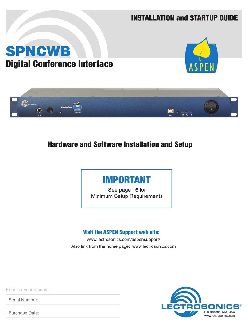
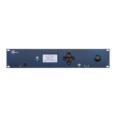
Lectrosonics SPNCWB Instruction manual

SPNCWB
Wideband Bridging Conference Interface
TECHNICAL DATA
Rio Rancho, NM, USA
www.lectrosonics.com
• Quad-referenceWidebandAcousticEcho
Cancellersupporting3-wayBridging
• Twomaximumspeedgrade,4thgeneration
SHARC®processors*
•DualCodecinterfaces
• TCP/IPEthernetAddressable
The SPNCWB wideband conference interface makes
telepresence and multi-site bridging simple and effec-
tive in any conference room, with full bandwidth audio
frequency response and a unique Quad-reference AEC.
Each conference connection includes a dedicated AEC
for fast and reliable echo cancellation:
• Telephoneline(POTS)
• Codec1
• Codec2
The fourth AEC is assignable to any final mix in the ma-
trixforpurposessuchasnoisecancellation(whenfeda
signalfromasamplingmicrophone).
The AEC converges very fast and will remain converged
during double-talk and any signal type, including sine
waves, enabled by an advanced DSP algorithm. Cancel-
lation depth increases with even with brief signal peaks
from the far ends.
The AEC in combination with the patented proportional
gainmixingalgorithm(US Patents 5,414,776 and 5,402,500)
provides outstanding audio quality without echo heard at
the far ends. Signals from the far ends of the conference
are routed to the local sound system and to three mixes
that are used as reference signals by the AEC. Audio
fromthelocalmicrophones(whichincludesfarendaudio
deliveredbylocalloudspeakers)isroutedtotheAECvia
another final mix for cancellation of the far end signals.
After processing, the output of the AEC is routed back to
the far ends through the matrix.
Three remote sites can be bridged with a local sound
system for a seamless telepresence or audio conference.
The far end audio signals participate in the same man-
ner as local microphones connected to the mixer.
A full complement of audio signal processing is provided
for all inputs and outputs. In addition, a proprietary NRF
(noisereductionlter)isprovidedoneachinputtosup-
press noise in severe conditions. The NRF employs a
proprietarynoisereductionalgorithmusinga1/3octave
analysis and downward expansion. The amount of noise
reduction applied to the signal at each input is adjustable
from6dBto35dBasneededforthesignalconditions
and individual preferences. The process is very effective,
withalmostnoaudibleartifactsuptoabout18dB.High-
er values are available for very poor conditions where
noise is extremely high and intelligibility is improved at
the expense of artifacts in the audio.
A two channel power amplifier is included for loudspeak-
ers in the local sound system. The power amplifier is
driven by final mix outputs from the matrix and has a full
set of signal processing, including delay, parametric EQ,
compressor and limiter. Class-D amplification with a late
generation component provides exceptional efficiency,
low heat and excellent audio performance. The amplifiers
cannot be damaged by wiring errors or unusual loads.
The processor interconnects with other ASPEN proces-
sorsviathe1Gbpbusbuiltintoallmodels.
* SHARC is a registered trademark of Analog Devices, Inc.
• FullyintegratedwithASPENdigitalmatrix
• AdaptiveProportionalGainAutomatic
MixingattheMatrixCrosspoints
• ThirdOctaveNoiseFilteroneachchannel
• Sigma-deltaclass-Daudiopowerampliers
Signal Flow
Two Codec interfaces and a telephone line are processed
and delivered to the ASPEN matrix in the same manner
as microphones are handled in an ASPEN mixer. Four ad-
ditional Virtual inputs receive signals from a built-in signal
generator, which is used for testing and diagnostics.
The AEC receives signals from two final mixes that
supply far end and local audio signals needed for echo
cancellation. The AEC output after cancellation is then
routed through the matrix to the appropriate Codec and
telephone line outputs.
Signal Processing
Each of the processing blocks shown above contains
multiple elements as shown here:

Logic Output Connections
Potentiometers and switches can be connected to rear
panel logic input controls to adjust levels or mute any
one or a group of inputs, crosspoints and outputs. Logic
outputs are used to drive LED indicators triggered by a
varietyoflogicinputactivityand/orthestatusofinputs,
presets and conference connections.
Headphonemonitor
withretractableknob
USBPort Alert
LED
Comm
LED
Power
LED
Ports and Connections
Extensive control options are available through serial,
ethernet, wired and logic ports.
• RS-232istypicallyusedwithtouchpanelcontrol
systems.
• Ethernetconnectivityallowsremoteaccessfor
setup and control with computer systems.
• WiredremotecontrolwithLectrosonicsdesktop
and wall mounted pushbutton panels is provided
throughtworearpanelCAT-5jacks.
• Hardwiredcontrolusingpots,switchesandLEDs
connectedtorearpanellogicI/Oportsallowsdi-
rect control of levels, modes and indicators. In con-
junction with the powerful, built-in macro language,
these controls can be used for a wide variety of
level adjustments, preset recalls, event triggered
indicators, room combining configurations, etc.
LED
380 TO
500 OHM
10K
LINEAR
POT
CW
CCW
IN 1
IN 3
ON
OFF
LOGIC OUTPUTS
GROUND
5VDC
LOGIC INPUTS
LOGIC
OUT 7
LOGIC IN 3
ANODE CATHODE
V
R
Anode
Cathode
CathodeAnode
Logic I/O connections
+
-
+
-
BTL output wiring
Power Amp Outputs
Theamplierisdesignedtoruncontinuously(idleorwith
aload)withoutheatbuildup,makingitidealforperma-
nent installations where prolonged operation is required.
Each output can drive a variety of loads, including loud-
speakers, long cable runs and headphones. The BTL
(bridgetiedload)congurationallowsthetwochannels
to be wired in parallel on a common load to double the
output power.
SPNCWB
ASPEN PORT
ETHERNET
RS-232
CODEC
1
POWER AMP
OUTPUTS
LINE
OUTPUTS
CODEC
2
LINE
INPUTS
CODEC
1
CODEC
2
12
TELEPHONE
LINE
REMOTE
CONTROL
RC 2
RC 1
SET
GND
+5V
PROG IN
PROG
OUT
S/N LABEL
DATECODE
100-240V
50/60Hz 35W
Made
in the
USA
RS-232port GigabitEthernetport Wiredremotecontrol
Logiccontrolconnections

Advanced Acoustic Echo
Cancellation
Conventional AEC algorithms face a trade-off between
convergence rate and depth. A fast convergence time
adapts quickly when a new conversation begins or when
a change occurs in the acoustic space, but the cancella-
tion depth is limited. Deeper cancellation requires more
time, so an echo may be heard at the far end until the
AEC achieves a fairly deep convergence.
An ideal AEC would react very quickly in the beginning
and then start applying more calculations over longer
time intervals to achieve a deeper cancellation as the
conference progresses.
The ideal echo canceller would also maintain con-
vergence regardless of signal types or levels. This is
precisely what the ASPEN echo canceller does. It is
designed to handle multi-site bridging and any number
of microphones simultaneously, and it works with the
gain proportional mixing algorithm perfectly.
An extremely difficult environ-
ment for an AEC is when local
sound reinforcement is being
used. Far side audio enters the
local microphones and mixes
with local audio and noise,
which makes it extremely diffi-
cult for the AEC to identify and
cancel the echo.
The example shown here is
a30secondrecordingofa
conference with local and far
side audio activity, plus a local
sound reinforcement system.
0-1.5seconds:
2-9.5seconds:
At10seconds:
TheAECwillnotdiverge(lose
convergence)unlesssome-
thing changes in the local
acoustic environment, such as
a microphone moving. When
this happens, it will converge
again and adapt to the new
echo path. These are usually
very subtle changes and go
completely unnoticed by the
conference participants.
Example of AEC activity over a 30 second period.
Far side audio (blue)
Local audio (tan)
0.02.5 5.07.5 10.0 12.5 15.0 17.5 20.0 22.5 25.0 27.5 30.0
time [s]
0.0
6.0
12.0
18.0
24.0
30.0
ERLE [dB]
AEC cancellation
depth (dB)
Path
change Double talk Mostly far
side audio
Mostly far
side audio

Control Panel Software
ASPEN software is provided on disk with each proces-
sor and downloadable from the support web site. The
package includes installers for USB Devices, the control
panelGUIandavarietyofdocumentation.
Control panels for the various processors open with a
diagram of the processors in the order that they are con-
nected through the rear panel ASPEN Ports.
Tabs across the top and bottom of the panel open
screens for each category of setup and configuration.

Macros and the ASPEN
Control Language
ASPEN macros are simply a series of instructions
expressed using the ASPEN Control language. The ele-
ments of the control language are as follows.
Commands
These are the familiar native commands of the AS-
PEN device, as documented in the “Command Set” in
thereferencemanualorundertheControlPanelHelp
menu. Ultimately, the purpose of the macro will be to
issue commands to the device in order to make it “do”
something, or to read out its current settings for use by
external controllers.
Variables
These are user defined global storage, used to pass
data within a macro, or between macros. Variables make
it possible for macros to have a “memory” of past ac-
tions, or to capture data for use within another macro,
at some other time. Arithmetic, comparison, and logical
operations can be performed with variables.
Expressions
These are used to compute logical or arithmetical results
using variables or constant values. Expressions make
it possible to perform arithmetic, create loops, or make
decisions using conditional statements.
Loops
These are “while-do” statements of the sort seen in
many other programming languages. Loops make it pos-
sible for a particular command to be run multiple times
as long as the state of some device property or the value
of some variable meets a specified condition.
Conditionals
These are “if-then-else” statements of the sort seen in
many other programming languages. Conditionals make
it possible for a macro to choose between alternative
actions on the basis of the current state of some device
property or the value of some user defined variable.
Commands, loops and conditionals are statements,
and can stand alone as a macro “line” or instruction.
Variables and expressions play a supporting role, with
variables commonly used in expressions and both often
found in update commands as the “argument.” Loops
and conditionals contain both expressions defining their
“condition” and commands to be executed as their “ac-
tions” if the condition is met.
Macros may include up to 64 “lines,” each line containing
one or more instructions, or statements. Multiple state-
mentsmustbeseparatedbya‘;’(semicolon)character.
Loop and conditional statements may be combined.
Thesemaximumlengthofamacrolineis115charac-
ters.
Macrosare“run”(executed)inresponsetosometrigger-
ing event, such as a serial command or the pressing of
a push button connected to a programmable logic input
pin. Applications such as room combining, courtroom
sound systems, and teleconferencing rely on macros to
make system setup changes “on the fly” in response to
buttonpanelactivityorserialcommandsfrom3rdparty
control systems.
Commands are used to control a variety of states and
configurations such as:
• ADFEFilters
• AudioInputs
• InputCompressors
• InputEQlters
• NoiseReductionFilters
• MatrixCrosspoints
• AudioOutputs
• OutputCompressors
• OutputEQFilters
• OutputLimiters
• RearPanelControl
• ProgrammableI/O
• PresetManagement
• MacroManagement
• RTCTimersandAlarms
• InternalSignalGenerators
• Events
• NetworkSetup

Multi-site Bridging
WiththeadditionofanASPENmixer,multiplefarsidescanbe
connectedtoeachotherandthelocalsiteusingamix-minus
approach.
Conferencing requires a minimum of four mixes:
• AECREFERENCEMIX
• AECSIGNALMIX
• SENDMIXES(includestheAECoutput)
• LOCALMIXES
The AECREFERENCEMIX is a mix of all the local
microphones which is routed through the AEC for echo
cancellation before being sent to the far sides. We recom-
mendthatyouusemixbus48forthismix.
The AECSIGNALMIX is a mix of all of the far side
signals which is routed to the AEC to identify and cancel
those that have entered the local microphones. We rec-
ommend that you use mix bus 47 for this mix.
The SENDMIXESconsistsof3elements:
• TheAECoutput(whichisamixofallthelocalmi-
crophonesminusanyechocausedbymicrophone/
speakercouplinginthelocalroom)
• Anyothersourcesyouwanttosendtothefarend
that are not microphones, such as program audio
• Thefarendsignalsyouwanttobridgetotheother
sites
A mix is assigned for each outbound signal. For ex-
ample, if you have just a telephone line, you will only
need one SEND mix for the Tel Line Out. If you have
one phone and two Codecs, you will need three SEND
mixes, one mix each for the Tel Line Out, Codec 1 Out
and Codec 2 Out. We recommend you use the mix bus-
ses46,45,44,etc.forthesesignalmixes.
The LOCALMIX includes the far end signals, program
audio, and any local microphones that require amplifica-
tion. Mix-minus routing can be created using multiple
crosspoints to improve gain-before-feedback in the local
sound system. We recommend that you use mix busses
1,2,3,etc.forthesemixestokeepthemwellseparated
in the matrix from the mixes used for conference con-
nections. There is no technical or performance reason
for this separation; it simply makes it easier to visualize
the matrix assignments during setup.
AEC
Signal
Input
Ref
Input
Tel Line In
148
47
463
245
44
Codec 1 Out
Codec 2 Out
Codec 2 In
Codec 1 In
Tel In + Local
Codec 1 + Local
Codec 2 + Local
Tel Line Out
AEC in (Signal Mix)
AEC out ( to Far Side)
AEC Reference Mix
AEC out ( to Far Side)
Local Mixes
Signal added to mix (matrix)
Mixes for output signals (outsource)
Finished Matrix Setup
Conference Board
Mixer Board
SPNCWB Conference Processor
ASPEN Mixer such as the SPN812

18April2013
581 Laser Road NE • Rio Rancho, NM 87124 USA • www.lectrosonics.com
(505) 892-4501 • (800) 821-1121 • fax (505) 892-6243 • [email protected]
Specifications
Acoustic Echo Canceller: 128 ms tail time - will never diverge, regardless of signal
type (i.e. sine wave)
Line Echo Canceller: 48 ms tail time
Telephone Hybrid Return Loss: 26 dB + line echo canceller = 45 dB
Audio inputs (Codec):
Gain: -20 dB to +20 dB, programmable in
1 dB steps
Input impedance: 15k ohm (differential); 375k (common)
Connector: 5-pin Phoenix
Audio outputs (Codec): Floating balanced
Nominal level: 0 dBu
Output impedance: 50 Ω
Input Dynamic Range (Codec): 102 dB (unweighted 20 - 20 kHz)
Output Dynamic Range (Codec): 105 dB (unweighted 20 - 20 kHz)
Audio Performance (Codec):
THD + noise: 0.01%
Front Panel Connectors: • 1/4 inch headphone monitor jack with level control
• Standard USB
Rear Panel Connectors:
Power: IEC 60320 C14
RS-232: DB-9
Ethernet: RJ-45
Programmable Logic I/O: DB-25
ASPEN port: Dual RJ-45
Remote control: Dual RJ-45
Power amp output: 5-pin Phoenix
Line Inputs/Outputs: (2) 5-pin Phoenix
Telephone Set/Line: (2) RJ-11
Proprietary network
Physical level: LVDS (Low Voltage DIfferential Signal)
high speed
Cable type: CAT-6
Transmission speed: 1 Gbps
Programmable control inputs
Number of inputs: 15
Analog voltage range: 0-5V
Logic input: TTL, LVTTL, CMOS, LVCMOS
Programmable control outputs
Number of logic outputs: 8
Logic control: active low
Max sink current: 100 mA
Max supply voltage: 40 V
Supply voltage for control I/O: 5 V
Max current: 750 mA
Cabled Remote Controls: Codec 1: Lectrosonics RCWTH4; RJ-45 jack
Tel: Lectrosonics RCWTH4; RJ-45 jack
Power requirements: 100-240 VAC, 50/60 Hz
Power consumption: 15 Watts
Dimensions:
Faceplate: Standard 19 inch 1RU
Housing (WxHxD): 17.50 x 1.72 x 7.25 inches
Weight: 3.56 lbs. (without AC cord)
Other manuals for SPNCWB
1
Table of contents
Other Lectrosonics Recording Equipment manuals

Lectrosonics
Lectrosonics SPNTrio Manual

Lectrosonics
Lectrosonics DM84 User manual

Lectrosonics
Lectrosonics SPNCWB Installation manual

Lectrosonics
Lectrosonics PDR User manual

Lectrosonics
Lectrosonics PDR User manual

Lectrosonics
Lectrosonics PDR User manual

Lectrosonics
Lectrosonics PDR User manual

Lectrosonics
Lectrosonics DM1612 User manual