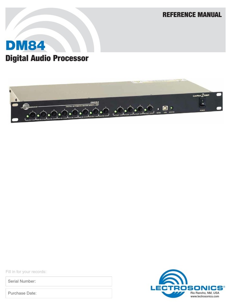
Lectrosonics DM1612 User manual

1
Reference Manual for Operation
Rio Rancho, NM – USA
Reference Manual
DM Series Digital Audio Processors
models
DM812, DM1612, DM1624
www.lectrosonics.com

2
DM Series Digital Matrix Processors

3
Reference Manual for Operation
Rio Rancho, NM – USA
IMPORTANT SAFETY INSTRUCTIONS
This symbol, wherever it appears, alerts you to the presence of uninsulated dangerous
voltage inside the enclosure -- voltage that may be sufficient to constitute a risk of
shock.
This symbol, wherever it appears, alerts you to important operating and maintenance
instructions in the accompanying literature. Please read the manual.
1) Read these instructions.
2) Keep these instructions.
3) Heed all warnings.
4) Follow all instructions.
5) Do not use this apparatus near water.
6) Clean only with a dry cloth.
7) Do not block any ventilation openings. Install in accordance with the manufacturer's
instructions.
8) Do not install near any heat sources such as radiators, heat registers, stoves, or other
apparatus (including amplifiers) that produce heat.
9) Do not defeat the safety purpose of the polarized or grounding-type plug. A polarized plug
has two blades with one wider than the other. A grounding type plug has two blades and
third grounding prong. The wider blade or the third prong are provided for your safety. If
the provided plug does not fit into your outlet, consult an electrician for replacement of the
obsolete outlet.
10)Protect the power cord from being walked on or pinched particularly at plugs, convenience
receptacles, and the point where they exit from the apparatus.
11)Only use attachments/accessories specified by the manufacturer.
12)Use only with the cart, stand, tripod, bracket, or table specified by the manufacturer, or
sold with the apparatus. When a cart is used, use caution when moving the cart/apparatus
combination to avoid injury from tip-over.
13)Unplug this apparatus during lightning storms or when unused for long periods of time.
14)Refer all servicing to qualified service personnel. Servicing is required when the apparatus
has been damaged in any way, such as power-supply cord or plug is damaged, liquid has
been spilled or objects have fallen into the apparatus, the apparatus has been exposed to
rain or moisture, does not operate normally, or has been dropped.
15)WARNING -- TO REDUCE THE RISK OF FIRE OR ELECTRIC SHOCK, DO NOT
EXPOSE THIS APPARATUS TO RAIN OR MOISTURE.

4
DM Series Digital Matrix Processors

5
Reference Manual for Operation
Rio Rancho, NM – USA
TABLE OF CONTENTS
General Overview ......................................................................................................................................... 9
Signal Flow ..................................................................................................................................................................... 9
Input Processing ........................................................................................................................................................... 11
Input Gain ............................................................................................................................................................. 11
Delay ..................................................................................................................................................................... 11
Filters .................................................................................................................................................................... 11
ADFE Filters ......................................................................................................................................................... 11
Compressor .......................................................................................................................................................... 11
Digital Matrix ................................................................................................................................................................. 12
Automixer Cell ...................................................................................................................................................... 12
Power of the Mix ................................................................................................................................................... 12
Crosspoint Gain .................................................................................................................................................... 12
Mixing Mode ......................................................................................................................................................... 12
Output Processing ........................................................................................................................................................ 13
Output Source Select ........................................................................................................................................... 13
Mic/line Output Channels ..................................................................................................................................... 13
Output Signal Processing Stages ......................................................................................................................... 14
Digital Delay ......................................................................................................................................................... 14
Filters .................................................................................................................................................................... 14
Compressor and Limiter ....................................................................................................................................... 14
Output Gain and Level Indicator ........................................................................................................................... 14
Hardware Front Panels .............................................................................................................................. 15
Hardware Rear Panels................................................................................................................................16
LCD Interface ............................................................................................................................................... 17
Operation with Front Panel Controls ............................................................................................................................. 17
NOTE: ................................................................................................................................................................... 17
Boot Sequence Screens ....................................................................................................................................... 17
General Overview - Menus and Screens................................................................................................. 18
Top Menu ...................................................................................................................................................................... 19
Setup Menu .................................................................................................................................................................. 19
Setup Screens .............................................................................................................................................................. 19
The “Back” Button ......................................................................................................................................................... 19
Top Menu .............................................................................................................................................................. 19
Setup Menus ........................................................................................................................................................ 19
Input Setup Screen ............................................................................................................................................... 19
Input Setup ................................................................................................................................................................... 19
Input Select ........................................................................................................................................................... 19
Input Setup - RP Gain .......................................................................................................................................... 19
Input Setup - Gain ................................................................................................................................................ 19
Input Setup - Mute ................................................................................................................................................ 19
Input Setup - Phase Inv ........................................................................................................................................ 19
Input Setup - PhanPwr ......................................................................................................................................... 19
Matrix Crosspoint Setup Screens ................................................................................................................................. 20
Setup - Matrix ....................................................................................................................................................... 20
Xpoint Setup Menu ............................................................................................................................................... 20
Xpoint Setup - MixMode ....................................................................................................................................... 20
Xpoint Setup - Gain .............................................................................................................................................. 20
Xpoint Setup - Mute .............................................................................................................................................. 20
Output Setup Screens .................................................................................................................................................. 21
Setup - Outputs .................................................................................................................................................... 21
Output Setup - Output Select ............................................................................................................................... 21
Output Setup - RP Gain ....................................................................................................................................... 21
Output Setup - Source .......................................................................................................................................... 21
Output Setup - Level ............................................................................................................................................. 21
Output Setup - Gain .............................................................................................................................................. 21
Output Setup - Mute ............................................................................................................................................. 21
Preset Setup Screens ................................................................................................................................................... 22
TopMenu - Presets ............................................................................................................................................... 22
Preset Control - PowUpDef .................................................................................................................................. 22
Preset Control - SetToFac .................................................................................................................................... 22
Preset Control - Store To ...................................................................................................................................... 22
Preset Control - Recall ......................................................................................................................................... 22
Preset Control Screens - Using the OK item on all screens ................................................................................ 22
Stacking Multiple Units ................................................................................................................................................. 22
System Information ....................................................................................................................................................... 23
General Settings ........................................................................................................................................................... 23
TopMenu - SysInfo ................................................................................................................................................ 23
System Information Screen .................................................................................................................................. 23
Setup - General .................................................................................................................................................... 23
General Setup - Mode .......................................................................................................................................... 23
Locking out the front panel controls .............................................................................................................................. 24
TopMenu - LockSet ............................................................................................................................................... 24
Lock Setup - Entering the Passcode .................................................................................................................... 24
Restoring the default passcode .................................................................................................................................... 24
Changing the Passcode ................................................................................................................................................ 25
Navigate to the Lock Setup Screen ...................................................................................................................... 25
Enter the existing passcode ................................................................................................................................. 25
Enter the new passcode ....................................................................................................................................... 25
Command View Screen ................................................................................................................................................ 26
6
DM Series Digital Matrix Processors
TABLE OF CONTENTS
Serial Port Speed Adjustment ...................................................................................................................................... 26
Leaving the Top Menu ................................................................................................................................................... 26
TopMenu - CmdView ............................................................................................................................................ 26
TopMenu - SerPort ............................................................................................................................................... 26
TopMenu - EXIT .................................................................................................................................................... 26
Installing LecNet2™ Software and USB Driver ..................................................................................... 27
Installing LecNet2™ Software ........................................................................................................................... 27
Installing the LecNet2™ USB Driver ................................................................................................................. 27
USB driver installation Windows XP) ................................................................................................................ 27
First time installation ......................................................................................................................................... 27
Installation additional Venue Receivers (or Lecnet2 devices) ........................................................................... 28
USB Driver Installation (Windows 2000) .............................................................................................................. 29
First Time Installation ........................................................................................................................................ 29
Firmware Updates....................................................................................................................................... 30
Using the Update Wizard ...................................................................................................................................... 30
Serial Interface & Control Commands .................................................................................................... 33
DM1624 General Commands ............................................................................................................................... 33
DM1624 Audio Input Commands .................................................................................................................................. 33
inact (input activity) ............................................................................................................................................... 33
incl (input clipping) ................................................................................................................................................ 33
indel (input delay) ................................................................................................................................................. 33
Serial Interface & Control Commands (cont'd)...................................................................................... 34
ingn (input gain) .................................................................................................................................................... 34
iniv (input phase invert) ........................................................................................................................................ 34
inlb (input channel label) ....................................................................................................................................... 34
inlv (input level) ..................................................................................................................................................... 34
inmt (input mute) ................................................................................................................................................... 34
Serial Interface & Control Commands (cont'd)...................................................................................... 35
inmttog (input mute toggle) ................................................................................................................................... 35
inph (input phantom power) .................................................................................................................................. 35
DM1624 Matrix Crosspoint Commands ....................................................................................................................... 35
xpgn (crosspoint gain) .......................................................................................................................................... 35
xpmode (crosspoint mix mode) ............................................................................................................................ 35
Serial Interface & Control Commands (cont'd)...................................................................................... 36
xpmt (crosspoint mute) ......................................................................................................................................... 36
xpmttog (crosspoint mute toggle) ......................................................................................................................... 36
DM1624 Audio Output Commands ............................................................................................................................... 36
outdel (output delay) ............................................................................................................................................. 36
outgn (output gain) ............................................................................................................................................... 36
Serial Interface & Control Commands (cont'd)...................................................................................... 37
outlb (output channel label) .................................................................................................................................. 37
outlv (output level) ................................................................................................................................................ 37
outmic (output mic level) ....................................................................................................................................... 37
outmt (output mute) .............................................................................................................................................. 37
outmttog (output mute toggle) .............................................................................................................................. 37
outsrc (output signal source) ................................................................................................................................ 37
Serial Interface & Control Commands (cont'd)...................................................................................... 38
DM1624 Input Compressor Commands ....................................................................................................................... 38
incpatt (input compressor attack time) ................................................................................................................. 38
incpgn (input compressor gain) ............................................................................................................................ 38
incpmug (input compressor makeup gain) ........................................................................................................... 38
incprat (input compressor ratio) ............................................................................................................................ 38
incprel (input compressor release time) ............................................................................................................... 38
incpthr (input compressor threshold level) ............................................................................................................ 38
Serial Interface & Control Commands (cont'd)...................................................................................... 39
DM1624 Output Compressor Commands .................................................................................................................... 39
outcpatt (output compressor attack time) ............................................................................................................. 39
outcpgn (output compressor gain) ........................................................................................................................ 39
outcpmug (output compressor makeup gain) ....................................................................................................... 39
outcprat (output compressor ratio) ....................................................................................................................... 39
outcprel (output compressor release time) ........................................................................................................... 39
outcpthr (output compressor threshold level) ....................................................................................................... 39
Serial Interface & Control Commands (cont'd)...................................................................................... 40
DM1624 Output Limiter Commands ............................................................................................................................. 40
outlmatt (output limiter attack time) ...................................................................................................................... 40
outlmrel (output limiter release time) .................................................................................................................... 40
outlmthr (output limiter threshold level) ................................................................................................................. 40
DM1624 Programmable I/O Commands ...................................................................................................................... 40
prgin (programmable input state) .......................................................................................................................... 40
prgout (programmable output state) ..................................................................................................................... 40
Serial Interface & Control Commands (cont'd)...................................................................................... 41
prgoutht (programmable output channel activity hold time) .................................................................................. 41
prgoutqt (programmable output channel activity qualification time) ..................................................................... 41
DM1624 Rear Panel Control Commands ..................................................................................................................... 41
rpingn (rear panel audio input gain) ...................................................................................................................... 41

7
Reference Manual for Operation
Rio Rancho, NM – USA
TABLE OF CONTENTS
rpingnmin (rear panel audio input gain minimum) ................................................................................................ 41
Serial Interface & Control Commands (cont'd)...................................................................................... 42
rpingnpre (rear panel audio input gain preset) ..................................................................................................... 42
rpingnst (rear panel input gain step change) ........................................................................................................ 42
rpoutgn (rear panel audio output gain) ................................................................................................................. 42
rpoutgnmin (rear panel audio output gain minimum) ............................................................................................ 42
rpoutgnpre (rear panel audio output gain preset) ................................................................................................. 42
Serial Interface & Control Commands (cont'd)...................................................................................... 43
rprest (restore rear panel settings) ....................................................................................................................... 43
rpsave (save rear panel settings) ......................................................................................................................... 43
DM1624 ADFE Commands .......................................................................................................................................... 43
Serial Interface & Control Commands (cont'd)...................................................................................... 44
ADFE Filter Numbers Mapped to Center Frequencies ......................................................................................... 44
Macros and Macro Control ........................................................................................................................ 45
About Macros ................................................................................................................................................................ 45
Rear Panel Control - Hardware ................................................................................................................. 46

8
DM Series Digital Matrix Processors

9
Reference Manual for Operation
Rio Rancho, NM – USA
General Overview
As digital technology continues to advance in a variety
of markets and products, considerable benefits also
evolve in audio processing systems for installed sound
systems that employ multiple microphones and loud-
speakers in a common acoustical space. The DM
Series digital processors take advantage of these
advances with hardware/software designs that address
modern applications in boardroom, courtroom, sound
reinforcement and teleconferencing systems.
The latest generation DSP microchips and microproces-
sors are the core of the engineering of the DM Series
products. The focus and purpose is to meet the require-
ments of modern applications and also the demands for
convenience and automation.
The diagram below depicts the overall structure of the
DM1624 processor. All models in the DM Series offer
the same signal processing functions, and vary only by
the number of audio inputs and outputs available.
Each input channel includes a high quality analog
preamplifier, with digital and analog level control to
maximize signal to noise ratio and minimize distorion,
followed by a 24-bit A-D converter. Extensive digital
signal processing is provided on each input channel.
The audio signal is then delivered to a digital matrix
processor for routing.
The digital matrix mixer distributes each input signal to
any selected combination of outputs, with level control
at each crosspoint. Each of the 24 outputs includes
extensive signal processing to optimize the mixed signal
for the intended purpose, such as sound reinforcement,
recording or teleconferencing.
Signal Flow
The basic structure of the DM processor consists of
three stages: Input, Matrix and Output. Each input
channel is processed and filtered as needed and the
signal is delivered into the matrix. The matrix processes
the signals and delivers them to the assigned outputs
and communicates with other devices in the system.
Each output receives signals from the mixing matrix, the
pink noise generator or the tone generator as needed
for setup, diagnostics or operation.
When multiple units are stacked, mixing data and the
digital audio are passed between the slave units and the
master unit through the expansion ports. Multiple units
can be stacked in a master/slave configuration to
expand the number of inputs to hundreds of channels.
The audio and data from all units in the stack is gath-
ered in the matrix in the master unit, which is where the
output signals are generated. The output signals for
channels 1 through 12 are sent to each slave through
the expansion bus. These signals are available on the
slave unit outputs 1 through 12, and repeated on
outputs 13 through 24 on the DM1624 only. The output
processing for the outputs is applied in the master unit
in the stack.
16 by 24+2
Mixing
Matrix
Input #1
Processing
Input #16
Processing
Output #1
Processing
Output #24
Processing
Tone
Generator
1 kHz, 0 dBu
Pink Noise
Generator
0 dBu
24 Output Submixes
2 Expansion Submixes
26 Automixing Aux. Data
2 Expansion Signals
26 Automixing Control Data
24 Output Submixes
2 Expansion Submixes
26 Automixing Aux. Data
2 Expansion Signals
26 Automixing Control Data
.
.
.
.
.
.
DM1624 Signal Flow Block Diagram
12 Final Mixes
12 Final Mixes

10
DM Series Digital Matrix Processors
16 by 24 (+ 2) Automatic Mixing Matrix
Signal Processing
Signal Processing
Signal Processing
Signal Processing
Signal Processing
Signal Processing
Signal Processing
Signal Processing
Signal Processing
Signal Processing
Signal Processing
Signal Processing
Signal Processing
Signal Processing
Signal Processing
Signal Processing
Signal Processing
Signal Processing
Signal Processing
Signal Processing
Signal Processing
Signal Processing
Signal Processing
Signal Processing
1 kHz Tone
Generator
Pink Noise
Generator
Cluster of Four SHARC
®
DSPs
SHARC is a registered trademark of
Analog Devices, Inc.
USB
Port
RS-232
Port
Prog I/O
Port
LCD
Buttons &
Rotary
Micro
Controller
Prog I/O Conn
2 x DB25
LecNet 2 Conn
1/8 '' Jack
Front & Rear
USB B Conn
Control
Signals
16
22
Tx
Tx
Rx
Rx
Digital
Audio
Network
Interface
(DANI)
12 + 2 Submixes + Mixing Control
24+ 2 Mixes + Mixing Control
24+2 Mixes + Mixing Control
Sync Audio Frame Sync
Quad RJ-45 Conn
A/DProg
Phan.
On/Off
A/DProg
Phan.
On/Off
A/DProg
Phan.
On/Off
A/DProg
Phan.
On/Off
A/DProg
Phan.
On/Off
A/DProg
Phan.
On/Off
A/DProg
Phan.
On/Off
A/DProg
Phan.
On/Off
A/DProg
Phan.
On/Off
A/DProg
Phan.
On/Off
A/DProg
Phan.
On/Off
A/DProg
Phan.
On/Off
A/DProg
Phan.
On/Off
A/DProg
Phan.
On/Off
A/DProg
Phan.
On/Off
A/DProg
Phan.
On/Off
Signal Processing
Signal Processing
Signal Processing
Signal Processing
Signal Processing
Signal Processing
Signal Processing
Signal Processing
Signal Processing
Signal Processing
Signal Processing
Signal Processing
Signal Processing
Signal Processing
Signal Processing
Signal Processing
16 Mic/Line Inputs
In 1
In 8
In 7
In 6
In 9
In 5
In 4
In 3
In 2
In 13
In 12
In 11
In 10
In 16
In 15
In 14
D/A
D/A
D/A
D/A
D/A
D/A
D/A
D/A
D/A Line/
Mic
D/A Line/
Mic
D/A Line/
Mic
D/A Line/
Mic
D/A
D/A
D/A
D/A
D/A
D/A
D/A
D/A
D/A Line/
Mic
D/A Line/
Mic
D/A Line/
Mic
D/A Line/
Mic
24 Outputs (16 Line + 8 Mic/Line)
Out 1
Out 9
Out 8
Out 7
Out 6
Out 5
Out 4
Out 3
Out 2
Out 12
Out 11
Out 10
Out 20
Out 19
Out 18
Out 17
Out 16
Out 15
Out 14
Out 13
Out 24
Out 23
Out 22
Out 21
M
S
M
S
M
S
M
S
M
S
M
S
M
S
M
S
M
S
M
S
M
S
M
S
M
S
M
S
M
S
M
S
M
S
M
S
M
S
M
S
M
S
M
S
M
S
M
S

11
Reference Manual for Operation
Rio Rancho, NM – USA
0 - 1s
0.5 ms steps
Delay Six Filter
Stages
Six ADFE
Filters Compressor
Level Meter
Clipping
Detector
Gain Reduction Indicator
Fine Gain & Polarity
-10 to 10 dB,
1 dB steps
Enable/Disable Threshold
Comp. Ratio
Attack TC
Release TC
Off, LP, HP, BP,
PEQ, LS, HS
6 or 12 dB/oct.
Butterworth or Bessel
when applicable
One of 16 Input Signal Processing Blocks
IndicatorIndicator
Activity Indicator
A/D
Input Gain & Polarity
-10 to +60 dB
1 dB steps
Coarse Gain
0 to 50 dB,
10 dB steps
Input Processing
Each input channel provides individual stages for gain,
delay, filtering and compression as shown in the illustra-
tion. Levels can be set up with the front panel LCD or
with the software GUI provided with the units.
Input Gain
The input preamplifier applies software controllable gain
with both analog and digital components, with the ratio
between them automatically optimized for maximum
signal to noise ratio. A single control point is provided to
simplify setup. A level indicator and clipping indicator
are provided in the GUI display.
Delay
A digital delay follows the input stage. A delay of up to 1
second can be applied in 0.5 ms increments.
Filters
Six digital filters are provided to compensate for differ-
ences between various microphones and other audio
sources.
ADFE Filters
Six ADFE (automatic digital feedback eliminator) filters
are provided on each input to suppress acoustic feed-
back that may occur. Applying ADFE at the input rather
than at the output allows the filters to deal exclusively
with the unique characteristics of the individual input
channel rather than with the composite of multiple
channels that appear at any one output.
Compressor
A sophisticated compressor stage is provided following
the other stages to control the dynamic characteristics
of the input. The compressor provides control over
threshold, compression ratio, plus attack and delay time
constants.
Details of the signal processing stages are explained in the
Online Help available after installing the software.

12
DM Series Digital Matrix Processors
+
Automixer
Cell
Submix
Submix
Crosspoint Gain
-70 to 20 dB
1 dB steps
Mixing Mode
- Auto
- Direct
- Override
- Background
One of 384 Matrix Crosspoints
Audio Input
Power of the Mix
Power of the
Submix
Power of the
Submix
Digital Matrix
The digital matrix provides signal routing and communi-
cation with other devices in the system, and applies
automatic mixing and level control. A single crosspoint
is shown here to illustrate the elegance of the matrix.
Automixer Cell
This is the core of the matrix where data is gathered
from other channels and devices to apply level control
for the automatic mixing algorithm, the mixing mode and
the selected crosspoint gain. The cell receives data
from the master unit in a multi-unit stacked configuration
and the slave units farther down in the chain.
Power of the Mix
This is the reference used to determine the gain to be
applied to each individual output channel. In a multi-unit
stacked configuration, this data is sent to the slaves
from the master unit.
Crosspoint Gain
This is the gain selected with the LCD interface or the
GUI that determines the level that will appear at the
output.
Mixing Mode
The automatic mixing algorithm applies a patented gain
proportional algorithm* that allows each input assigned
to a particular crosspoint to behave differently relative to
the other inputs assigned to the crosspoint.
Four different modes are available:
Auto - In automatic mode the input applied to the
crosspoint is mixed into the output channel using the the
Adaptive Proportional Gain automixing algorithm in the
normal manner. This is the most common setting.
Direct - In Direct mode the automixing algorithm is
bypassed.
Override - Override mode is selected when it is re-
quired that the input applied to the crosspoint always
dominates the output channel when it becomes active.
Background - Background mode is selected when it is
required that the input applied to the crosspoint domi-
nates the output channel only when all other inputs are
inactive.
* US Patents 5,414,776 and 5,402,500

13
Reference Manual for Operation
Rio Rancho, NM – USA
Output Processing
Each output can receive signals from either the matrix,
the pink noise generator, the tone generator, or from the
master unit DANI source (if it is operating in a multi-unit
"stacked" configuration).
Output Source Select
The digital matrix delivers the audio signals used in
normal operation. The pink noise source can be used
for sound masking during operation, and for equalization
during setup. The tone generator is used for level
adjustments and signal routing diagnostics.
The Master/Slave switch selects whether the audio
signal at the output channel will come from the unit
itself, or from the master unit DANI (digital audio net-
work interface) source. When the unit is operating as a
slave, the signal will come from the DANI source and
any adjustments made on the output of the slave unit
will have no effect.
Details of the signal processing stages are explained in the
Online Help available after installing the software.
Mic/line Output Channels
Some outputs include an attenuator to reduce the
output level from line to mic level. The passive attenua-
tor does not change the signal to noise ratio of the
signal, but simply applies 40 dB of attenuation to reduce
the signal level.
Signal Processing D/A
M
S
1 kHz Tone
Generator
Pink Noise
Generator
Digital Matrix
Tx
Tx
Rx
Rx
Digital
Audio
Network
Interface
(DANI)
Quad RJ-45 Conn
Line/
Mic
NOTE: certain output channels
provide an attenuator to reduce
the signal to microphone level.
IMPORTANT:
Even though the output level adjustment provides up to
70 dB of attenuation, a line level output should not be
used to deliver a mic level signal - doing so will cause
the signal to noise ratio to be reduced by 40 dB. Always
use a mic/line switchable output for mic level signals.
Signal Processing D/A Out 20
M
S
1 kHz Tone
Generator
Pink Noise
Generator
Digital Matrix
Tx
Tx
Rx
Rx
Digital
Audio
Network
Interface
(DANI)
Quad RJ-45 Conn
NOTE: the M/S (master/
slave) switch selects the
signal that the output
channel will deliver when the
unit is operating as a slave in
a "stacked" configuration.

14
DM Series Digital Matrix Processors
Activity Indicator
Output Gain
-70 - +20 dB
1 dB steps
One of 24 Output Signal Processing Blocks
Nine Filter
Stages
Delay Compressor Limiter
Level Meter
Off, LP, HP, BP,
PEQ, LS, HS
6 or 12 dB/oct.
Butterworth or Bessel
when applicable
0 - 5s
0.5 ms steps
Threshold
Comp. Ratio
Attack TC
Release TC
Indicator
Activity Indicator
Gain Reduction Indicator
Threshold
Comp. Ratio
Attack TC
Release TC
Output Signal Processing Stages
Each output channel provides a delay, nine filters, plus a
compressor and limiter to idealize the channel for its
function in the sound system.
Digital Delay
Delay on the output signal is normally used for time
alignment when loudspeakers are positioned in different
locations with overlapping coverage patterns that cause
comb filtering. The signal can be delayed up to 5
seconds in 0.5 ms increments to eliminate comb filtering
and improve intelligibility.
Filters
Up to nine filters can be implemented at each output to
idealize the output channel equalization and implement
crossover networks for bi-amped or tri-amped loud-
speaker systems.
The filter types include:
Low pass
High pass
Band pass
Parametric EQ
Low shelving
High shelving
Filter slopes can be selected with 6 or 12 dB per octave
Butterworth or Bessel parameters. Multiple filters can
be assigned to creater steeper slopes in 6 dB steps.
Compressor and Limiter
A versatile compressor and limiter are provided at each
output to control the average level and dynamics of the
audio signal, and restrict the maximum output level to
optimize the channel for its purpose. Compression is
often needed when the channel is feeding a recorder,
and limiting is often used to protect a loudspeaker
system and reduce distortion and amplifier overload.
Compressor adjustment parameters include:
Threshold
Attack
Release
Compression ratio
Makeup gain
Limiter adjustment parameters include:
Threshold
Attack
Release
Output Gain and Level Indicator
The output level can be adjusted from - 70 dBu to +20
dBu in 1 dB steps to perfectly match the requirements of
the device being fed by the channel. A bar graph is
provided by the on screen GUI to accurately indicate the
output level as it operates and is adjusted.

15
Reference Manual for Operation
Rio Rancho, NM – USA
Hardware Front Panels
The front panels of the DM Series components provide
USB and LCD interfaces. The USB port is provided on
the front panel as a convenience, when adjustments
need to be made after the unit is installed. The LCD
interface is typically used for minor adjustments to
various levels.
The front panel LCD controls can be locked out with
special button presses to prevent tampering and inad-
vertent adjustments. The control interface is the same
for all three models, since the difference between them
is simply the number of inputs and outputs.
DM1624 - 16 inputs, 24 outputs
DM1612 - 16 inputs, 12 outputs
DM812 - 8 inputs, 12 outputs

16
DM Series Digital Matrix Processors
Hardware Rear Panels
DM1624 - 16 inputs, 24 outputs
DM1612 - 16 inputs, 12 outputs
DM812 - 8 inputs, 12 outputs
LecNet DSP
MIC/LINE IN
7856341211 1291078563412
15 1613 1411 12910
MIC/LINE IN
LINE OUT
EXPANSION
TX
RX
AB
1 - GND
2 - IN 1
3 - IN 3
4 - IN 5
5 - IN 7
25
13
14
1
6 - IN 9
7 - IN 11
8 - GND
9 - OUT 1
10 - OUT 3
11 - OUT 5
12 - OUT 7
13 - GND
14 - +5V
15 - IN 2
16 - IN 4
17 - IN 6
18 - IN 8
19 - IN 10
20 - +5V
21 - OUT 2
22 - OUT 4
23 - OUT 6
24 - OUT 8
25 - +5V
PROGRAMMABLE
INPUTS / OUTPUTS
RS-232
USB
POWER
MADE IN U .S.A.
DIGITAL AUTOMATIC MATRIX MIXER + DSP
2
LecNet 2 MIC/LINE OUT
1 - GND
2 - IN 12
3 - IN 14
4 - IN 16
5 - IN 18
6 - IN 20
7 - IN 22
8 - GND
9 - OUT 9
10 - OUT 11
11 - OUT 13
12 - OUT 15
13 - GND
14 - +5V
15 - IN 13
16 - IN 15
17 - IN 17
18 - IN 19
19 - IN 21
20 - +5V
21 - OUT 10
22 - OUT 12
23 - OUT 14
24 - OUT 16
25 - +5V
TX
RX
U.S. Patent Number: 5,414,776
This device complies with Part 15 of the FCC rules.
Operation is subject to the following two conditions:
(1) This device may not cause harmful interference,
and (2) this device must accept any interference
received, including interference that may cause
undesired operations.
90–240V 50/60Hz 30W
No User Serviceable PartsInside
MIC/LINE IN
7856341211 1291078563412
LINE OUT
EXPANSION
RX
AB
1 - GND
2 - IN 1
3- IN 3
4 - IN 5
5 - IN 7
25
13
14
1
6 - IN 9
7 - IN 11
8- GND
9 - OUT 1
10 - OUT 3
11 - OUT 5
12 - OUT 7
13- GND
14 - +5V
15 - IN 2
16 - IN 4
17 - IN 6
18- IN 8
19 - IN 10
20 - +5V
21 - OUT 2
22 - OUT 4
23- OUT 6
24 - OUT 8
25 - +5V
PROGRAMMABLE
PROGRAMMABLE
INPUTS/ OUTPUTS
RS-232
LecNet 2
MIC/LINE OUT
TX
U.S. Patent Number: 5,414,776
USB
RX TX
MADE IN U .S.A.
Thisdevice complieswith
Part 15 of the FCC rules.
Operation issubject to the
following two conditions: (1)
Thisdevice may not cause
harmful interference, and (2)
thisdevice must accept any
interference received, including
interference that may cause
undesired operations.
POWER
90–240VAC / 30W
LecNet DSP
MIC/LINE IN
7856341211 1291078563412
15 1613 1411 1291023 2421 2219 2017 1815 1613 14
MIC/LINE IN
LINE OUT
LINE OUT
EXPANSION
TX
RX
AB
1 - GND
2 - IN 1
3 - IN 3
4 - IN 5
5 - IN 7
25
13
14
1
6 - IN 9
7 - IN 11
8 - GND
9 - OUT 1
10 - OUT 3
11 - OUT 5
12 - OUT 7
13 - GND
14 - +5V
15 - IN 2
16 - IN 4
17 - IN 6
18 - IN 8
19 - IN 10
20 - +5V
21 - OUT 2
22 - OUT 4
23 - OUT 6
24 - OUT 8
25 - +5V
PROGRAMMABLE
INPUTS / OUTPUTS
RS-232
USB
POWER
MADE IN U .S.A.
DIGITAL AUTOMATIC MATRIX MIXER + DSP
2
90–240VAC / 30W
LecNet 2 MIC/LINE OUT
MIC/LINE OUT
1 - GND
2 - IN 12
3 - IN 14
4 - IN 16
5 - IN 18
6 - IN 20
7 - IN 22
8 - GND
9 - OUT 9
10 - OUT 11
11 - OUT 13
12 - OUT 15
13 - GND
14 - +5V
15 - IN 13
16 - IN 15
17 - IN 17
18 - IN 19
19 - IN 21
20 - +5V
21 - OUT 10
22 - OUT 12
23 - OUT 14
24 - OUT 16
25 - +5V
TX
RX
U.S. Patent Number: 5,414,776
No User Serviceable Parts Inside
This device complies with Part 15 of the FCC rules.
Operation is subject to the following two conditions:
(1) This device may not cause harmful interference,
and (2) this device must accept any interference
received, including interference that may cause
undesired operations.
Serial Number
Here

17
Reference Manual for Operation
Rio Rancho, NM – USA
LCD Interface
Operation with Front Panel Controls
Some adjustments, such as levels and mute activity, can
be made to DM Series processors without a computer
using the front panel LCD interface. While it is highly
recommended that the supplied GUI software be used,
the ability to make minor adjustments without a com-
puter is often valuable.
Direct interaction with the processor is provided using
the front panel buttons, the rotary encoder knob and the
LCD. A variety of menus and setup screens are pro-
vided. This interface is used mainly for adjustments to
input and output levels. Use the GUI for other functions.
Boot Sequence Screens
The first screen displays the model number.
A second screen is then displayed briefly showing the
serial number and the firmware version.
The display then returns to the first screen showing the
model number, indicating that the unit has completed
boot sequence and is running.
Press the rotary encoder knob to move to the Top Menu
after the boot sequence is completed.
PUSH FOR
MENU/SELECT
BACK
Rotary encoder control. Rotate to
select menu item and press to enter
the submenu or setup screen.
“Back” button used to save settng
and return to previous menu.
Item select buttons used on setup screens.
NOTE:
Adjustments made with the LCD controls are real time. As each setting is
made, the result will be heard immediately.

18
DM Series Digital Matrix Processors
Top Menu
When the encoder knob is pressed at the the model number
screen, the screen defaults to the TopMenu. Rotate the knob to
select the menu item. The Setup item is selected in this ex-
ample. Press the rotary encoder knob to select the Setup menu.
Top Menu
Setup Menus
The Setup menu lists a number of setup screen items. Rotate
the encoder knob to select the desired menu item, then press it
to enter the selected setup screen. In this example, the Input
Setup item is selected.
Setup Menu
PUSH FOR
MENU/SELECT
BACK
The “Back” Button
From any screen or menu, the lower
button to the left of the display will
return to the previous screen.
General Overview - Menus and Screens
Input Setup Screen
This example shows the Input Setup Screen that appears after
the encoder knob is pressed in the Top Menu with this item
selected. The selected input to be adjusted is shown in the
upper right section of the screen.
Six buttons under the display are used to select the items listed
across the bottom of the screen. Pressing the button under the
item on the screen will select the item and show its setting. In
this example, the RPG item is selected (highlighted) and the
current setting is shown (0dB).
Setup Screens
Item Select buttons

19
Reference Manual for Operation
Rio Rancho, NM – USA
Input Setup - RP Gain
Select RPG to view/change the rear panel gain setting for the selected
input channel. This setting is normally controlled by hardware (ie. pots,
switches) connected to the programmable input ports on the rear panel
of the unit.
NOTE: RP Gain is an attenuator only, with a range from 0dB to -30dB.
Input Setup - Gain
Select GAI to view/change the input channel gain. Rotate the encoder
knob to select the desired gain. The gain that can be applied to each
input ranges from -10dB to +60dB in 1dB increments.
Input Setup - Mute
Select MUT to view/change the mute state of the selected input. Rotate
the encoder knob to change the state. In this example, Input 1 is not
muted - in other words, the sound from this channel is turned on.
Input Setup - Phase Inv
Select INV to adjust the audio phase invert status of the selected input.
Rotate the encoder knob to toggle between Off (phase not inverted) and
On (phase inverted).
Input Select
Select IN to choose the desired input channel. The channel number in
the upper right hand section of the screen will be highlighted. Rotate the
encoder knob to select the input channel and press it to accept the
selection.
NOTE: select the desired input channel before making any of the
following adjustments.
Input Setup - PhanPwr
Select PHA to turn phantom power on or off for the selected input.
Rotate the encoder knob to toggle between choices On or Off.
Press the BACK button to the left of the display to return
to the Setup Menu from any of the Input Setup screens.
Input Setup
NOTE: select the input channel to be
modified with the item select buttons before
moving to the following steps.

20
DM Series Digital Matrix Processors
Setup - Matrix
Navigate to the Setup menu and rotate the encoder knob to select
Matrix, as shown in this example. Press the encoder knob to move to
the Xpoint Setup (matrix crosspoint) setup screen.
Xpoint Setup Menu
Matrix crosspoints are configured from this screen, which contains
settings for a single crosspoint. The selected output and input are
shown at the upper right section of the screen. In this example the
settings for crosspoint 1,1 (routing input 1 to output 1) are shown. To
change the output channel, select item OUT. To change the input
channel, select item IN. The corresponding channel number will be
highlighted as in this example. Rotate the encoder knob to select the
desired channel, and press it to accept the selection.
Xpoint Setup - MixMode
Select MIX to view/change the Mix Mode for the selected crosspoint.
Rotate the encoder knob to select the desired mode. MixModes are
explained on page 9 as used in various applications.
Xpoint Setup - Gain
Select GAI to view/change the gain for the selected crosspoint. After the
desired input and output have been selected, adjust the gain to be
applied at this crosspoint. Values range from -70dB to +20dB in 1 dB
increments.
Xpoint Setup - Mute
Select MUT to view/change the mute state of the selected crosspoint.
Rotate the encoder knob to toggle between choices Mute and Unmute.
Press the BACK button to the left of the display to return to
the Setup Menu from any of the Crosspoint Setup screens.
Matrix Crosspoint Setup Screens
NOTE: Select the desired matrix crosspoint before
making the following adjustments.
This manual suits for next models
3
Table of contents
Other Lectrosonics Recording Equipment manuals

Lectrosonics
Lectrosonics SPNTrio Manual

Lectrosonics
Lectrosonics SPNCWB Instruction manual

Lectrosonics
Lectrosonics PDR User manual

Lectrosonics
Lectrosonics DM84 User manual

Lectrosonics
Lectrosonics PDR User manual

Lectrosonics
Lectrosonics SPNCWB Installation manual

Lectrosonics
Lectrosonics PDR User manual

Lectrosonics
Lectrosonics PDR User manual