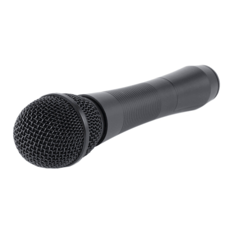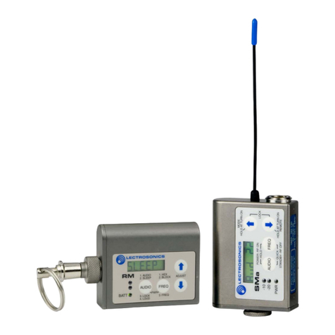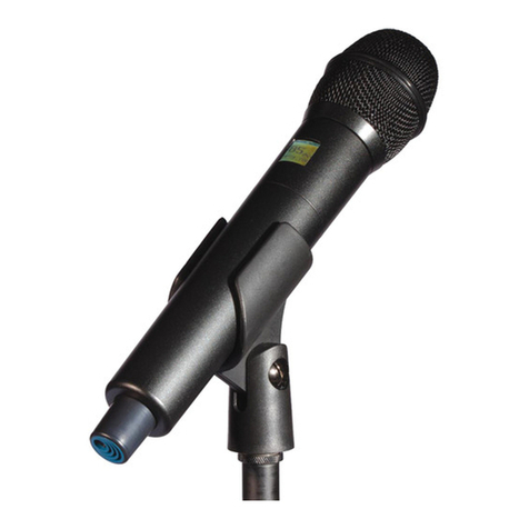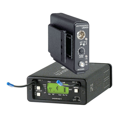
Synthesized UHF Hand-Held Transmitter
Rio Rancho, NM 5
Compatibility Modes
The transmitter was designed to operate with Lectro-
sonics Digital Hybrid Wireless™ receivers and will yield
the best performance when doing so. However, due to
the flexibility of digital signal processing, it is also able
to operate with Lectrosonics 200 Series, Lectrosonics
100 Series, IFB and certain non-Lectrosonics analog
receivers in special compatibility modes. (Contact the
Lectrosonics Sales Department for a complete list of
compatible receivers.)
Pilot Tone Squelch
The benefit of the pilot tone squelch system is that the
associated receiver will remain muted until it receives
the pilot tone from the matching transmitter, even if a
strong RF signal is present on the carrier frequency
of the system. All 400 Series transmitters use one
of 256 different ultrasonic tones between 25 and 32
kHz to modulate the carrier to operate the receiver
squelch. The pilot tone frequency is chosen according
to which of the 256 channels has been selected by the
frequency switch setting. This ensures that all transmit-
ters in a system have different pilot tone frequencies so
that even spurious RF from the wrong transmitters can’t
open the receiver squelch.
Wide-Band Deviation
The ±75 kHz deviation dramatically improves the cap-
ture ratio, signal to noise ratio and dynamic range of a
wireless system.
Input Limiter
A digitally-controlled limiter and a precise, 16-position
attenuation control allow a very wide range of gain set-
tings based on the source volume, thus optimizing the
signal-to-noise performance in any situation. The result
is the widest dynamic range of any wireless condenser
microphone today.
Long Battery Life
Switching power supplies throughout the design allow
over 3.5 hours of operation using a single 9 VDC alka-
line battery. (A 9 VDC lithium battery will provide over
6.5 hours of operation.) The battery contacts are spring
loaded to prevent “rattle” as the unit is handled.
Frequency Selection
The transmitter section uses a synthesized, frequency
selectable main oscillator. The frequency is extremely
stable over a wide temperature range and over time.
Two 16-position rotary switches, located under the
battery door, provide 256 frequencies in 100 kHz steps
over a 26.5 MHz range. This alleviates most carrier in-
terference problems in mobile or traveling applications.
Circulator/Isolator
The RF output circuit includes a one way circulator/
isolator using magnetically polarized ferrite. This device
greatly reduces RF intermodulation produced when
multiple transmitters are used at separations of less
than five feet. It also provides additional RF output
stage protection but is rarely seen in a wireless micro-
phone transmitters due to the considerable expense.
Antenna
The highly efficient antenna uses the lower half of the
printed circuit boards as one radiating element, with the
upper half of the PC boards and the mic capsule as the
other half of the dipole configuration. This allows the mic
to be held in any position, since the user’s hands have
little or no effect on the radiated power.
Microphone Element
The UT handheld transmitter is available with any of
three capsule types: the VMC cardioid condenser, the
VMO omni condenser and the VMS super-cardioid
condenser. All three are mounted with tuned suspen-
sions in order to eliminate handling noise. Each capsule
is also mated with the unique VariMic™ preamp ar-
rangement allowing for custom-tailoring the frequency
response based on application.
