LED2WORK TUBELED 40 Element DC User manual

/ 2014/35/EU
Betriebsanleitung
User Instructions
BA 06/2021
TUBELED_40 Element
MASCHINENBELEUCHTUNG
LED Maschinenleuchte
MACHINE LIGHTING
LED machine luminaire

2 | BA TUBELED_40 Element . BA 06/2021
| Inhalt
1Bestimmungsgemäße Verwendung Seite 3
2Zum sicheren Betrieb Seite 3
3Sicherheitshinweise Seite 4
4Montage und Befestigung Seite 4
5Anschluss Seite 5
6 Wartung und Pflege Seite 6
7Gewährleistung Seite 7
8Entsorgung Seite 7
9Kundenbetreuung Seite 7
10 Technische Daten Seite 8
11 Zeichnung Seite 9
| Struktur der Sicherheits- und ergänzenden Hinweise
In dieser Betriebsanleitung sind wichtige Hinweise mit Signalwörtern oder Symbolen
gekennzeichnet.
Einige Signalwörter bezeichnen die Abstufung einer möglichen Verletzungsgefahr.
Farben und die unterschiedlichen Grauabstufungen und Dreiecksymbole unterstreichen
den Gefährdungsgrad optisch.
zeigt eine unmittelbar gefährliche Situation an, die, wenn nicht ver-
mieden, zum Tod oder ernster Verletzung führt.
zeigt eine potenziell gefährliche Situation an, die, wenn nicht vermie-
den, zum Tod oder ernster Verletzung führen kann.
zeigt eine potenziell gefährliche Situation an, die, wenn nicht vermie-
den, zu geringfügiger oder leichter Verletzung führen kann.
zeigt eine potenziell gefährliche Situation an, die, wenn nicht vermie-
den, zu Sachschäden führen kann.
gibt Ihnen zusätzliche Informationen für die sichere und efziente
Verwendung des Produkts.
verweist auf die Einhaltung dieser Betriebsanleitung.
CE-Kennzeichnung: bestätigt die Konformität mit den geltenden
Normen und Rechtsvorschriften.

| 3
TUBELED_40 Element
www.led2work.com
1 | Bestimmungsgemäße Verwendung
Die Leuchte dient zur Beleuchtung und ist für den Dauerbetrieb geeignet.
Anschlusswerte siehe „Technische Daten“. Die Versorgungszuleitung wird über eine
M12 Steckverbindung an der Leuchte angeschlossen.
2 | Zum sicheren Betrieb
Die auf dem Typenschild angegebenen Betriebsparameter der LED-Leuchte müssen
mit den Versorgungsparametern der Maschine bzw. des Trafos übereinstimmen.
Die Sicherheitshinweise sowie alle anderen Informationen dieser
Bedienungsanleitung sind unbedingt zu befolgen. Lesen Sie sich
die gesamte Betriebsanleitung vor der Montage und Inbetriebnahme
aufmerksam durch.
Halten Sie die Betriebsanleitung, wenn möglich, beim Gerät ver-
fügbar. Sie muss aufbewahrt und bei Weitergabe des Produktes an
Dritte mit ausgehändigt werden.
Die Leuchte darf keinesfalls mit Tüchern, Folien o. anderem abge-
deckt werden. Objektabstand von der Leuchte mindestens 10 cm.
Maschinen können durch verschiedene Einflüsse Spannungs-
spitzen abgeben. Diese Spannungsspitzen bei der Stromver-
sorgung über Maschinen sind zu vermeiden: Verwenden Sie
ausschließlich geregelte 24V DC Schaltnetzteile, keine Trafos mit
Gleichrichter, da diese durch Induktivitäten Spannungsspitzen ab-
geben können.
Hot Plugging ist zu vermeiden (Anschluss der Leuchte an ein
Netzteil, welches bereits am Netz angeschlossen ist), da dieses
zur Zerstörung der LED-Leuchte führen kann.
Im Betrieb der Leuchte in einem 220 - 240V AC Netz können bei
Anlaufen größerer Abnehmer (Induktivitätsverursacher), die eben-
falls aus diesem Netz versorgt werden, sehr starke Störspitzen
auftreten. Die Abweichung darf max. ± 10% betragen.
TUBELED_40 Element DC
TUBELED_40 Element AC
Betreiben Sie die Leuchte nur im befestigten Zustand.

4 | BA TUBELED_40 Element . BA 06/2021
Bei Befestigung der Leuchte ist darauf zu achten, dass die Leuchte
sicher und stabil befestigt wird. Beim Herunterfallen der Leuchte be-
steht auf Grund des Eigengewichts Verletzungsgefahr!
4 | Montage und Befestigung
Die LED-Leuchte vor der Installation auf Vollständigkeit und eventuelle Schäden über-
prüfen. Leuchte oder Zubehör nicht benutzen, wenn diese beschädigt sind, da Verlet-
zungsgefahr besteht.
Die LED-Leuchte wird vollständig montiert ausgeliefert und darf nur so betrieben wer-
den. Befestigt wird die Leuchte über optionale Befestigungsteile:
Best.-Nr.
TUBELED_40 Leuchtenhalter, Aluminium, 1 Paar 210200-06
TUBELED_40 Montagewinkel, V2A, 1 Paar 210200-11
TUBELED_40 Montagewinkel, V2A, 1 Paar, inkl. Magnet 210200-12
TUBELED_40 Leuchtenhalter ± 180°, VA, 1 Paar 210200-14
3 | Sicherheitshinweise
Einbau und Installation elektrischer Geräte dürfen nur durch Elek-
trofachkräfte erfolgen. Befolgen Sie die fünf Sicherheitsregeln
nach DIN VDE 1005. Bei Nichtbeachten können Schäden an der
LED-Leuchte, Brand oder andere Gefahren entstehen.
Gefahr durch elektrischen Schlag! Vor Arbeiten an Gerät oder
Last freischalten. Dabei alle Leitungsschutzschalter berücksichti-
gen, die gefährliche Spannungen an Gerät oder Last liefern. Auch
bei nur ausgeschaltetem Gerät ist die Last nicht galvanisch vom
Netz getrennt.
Verwenden Sie das Gerät nur in technisch einwandfreiem Zu-
stand, sicherheits- und gefahrenbewusst. Sind Warnhinweise bzw.
-symbole auf der Leuchte angebracht, dürfen diese nicht entfernt
werden.

| 5
TUBELED_40 Element
www.led2work.com
5 | Anschluss
Geeignetes Anschlussmaterial, Leitungen und Zubehör finden Sie im Zubehörangebot
von LED2WORK.
An der Leuchte befindet sich ein Eingang
für einen M12-Steckverbinder A-kodiert.
Über diese Buchse wird die Leuchte mit
24V DC Festspannung, ausgehend von
einem Betriebsgerät, verbunden.
Schemazeichnung M12 A-kodiert
43
12
5
Mögliche Varianten Steckverbinder M12 A-kodiert
PIN-Belegung
PIN 1 = 24V DC
PIN 2 = nicht belegt
PIN 3 = GND
PIN 4 = 24V DC
PIN 5 = nicht belegt
PIN 3 = 0V DC. An PIN 1 oder an PIN 4 können 24V DC zur Versor-
gung angelegt werden! Es ist nicht nötig PIN 1 und PIN 4 zugleich
zu belegen.
Die PIN-Belegung des M12 Steckverbinders ist wie folgt:
TUBELED_40 Element DC
Durchgangsverdrahtung (Kaskadierung):
Mit Durchgangsverdrahtung (kaskadierbar) können Sie mehrere
Leuchten, die dafür vorgesehen sind, elektrisch verketten.
Die Gesamtstromaufnahme darf 8A DC bei tamax. +30°C
(bzw. 7A DC bei tamax. +40°C) nicht übersteigen.

6 | BA TUBELED_40 Element . BA 06/2021
6 | Wartung und Pege
Die LED-Leuchte ist für Sie wartungsfrei. Nehmen Sie keine Veränderungen an der
Leuchte vor (bis auf die in dieser Betriebsanleitung enthaltenen Informationen zur
Montage).
Die in der Leuchte verwendeten LED-Leuchtmittel sind sehr langlebig und können nicht
ausgetauscht werden.
Schalten Sie die Leuchte vor einer Reinigung ab und lassen Sie sie vollständig abküh-
len. Reinigen Sie die Außenseite der Leuchte mit einem weichen, trockenen, sauberen
Tuch. Für die Entfernung von stärkeren Verschmutzungen können Sie das Tuch mit
Wasser anfeuchten. Verwenden Sie niemals aggressive Reinigungsmittel, da diese zu
Verfärbungen des Gehäuses führen können.
Die PIN-Belegung des M12 Steckverbinders ist wie folgt:
PIN allocation
PIN 1 = nicht belegt Braun
PIN 2 = Außenleiter/Phase (L) Schwarz
PIN 3 = Neutralleiter (N) Grau
PIN 4 = Schutzleiter (PE) Grün/Gelb
Schemazeichnung M12 S-kodiert
4
1
2
3
TUBELED_40 Element AC
An der Leuchte befindet sich ein Eingang über einen M12 Sensor Steckverbinder S-ko-
diert. Über diesen wird die Leuchte mit geeignetem Anschlussmaterial an ein 230V AC
Netz angeschlossen.
Die Leuchte darf nur im lastfreien Zustand angeschlossen werden,
da es sonst zur Zerstörung der Leuchte kommen kann. Das heißt,
wird die Leuchte direkt an eine Maschine oder ein 230V Netz
angeschlossen, müssen diese zur Installation ausgeschaltet und
lastfrei sein.

| 7
TUBELED_40 Element
www.led2work.com
8 | Entsorgung
Die Leuchte muss gemäß den länderspezifischen Vor-
schriften an einem geeigneten Entsorgungspunkt zum
Recyceln von Elektro- und Elektronikgeräten entsorgt
werden. (WEEE-Nr. 32828318)
9 | Kundenbetreuung
Bei Problemen oder Fragen zu diesem Produkt kontaktieren Sie uns bitte!
Per Telefon: +49 7231 44920-00
Mo bis Do 8:00 Uhr bis 12:00 Uhr und 13:00 Uhr bis 16:30 Uhr
Fr 8:00 Uhr bis 12:00 Uhr und 13:00 Uhr bis 15:00 Uhr
Per e-mail: info@led2work.com
Für Schäden, die durch die Verwendung ungeeigneter Reinigungs-
mittel entstehen, wird keine Gewährleistung übernommen. Der
Hersteller haftet auch nicht für direkte oder indirekte Folgeschäden
durch unautorisierten Eingriff in die Leuchte.
7 | Gewährleistung
Wir übernehmen für dieses Gerät 36 Monate vom Kaufdatum an volle Gewähr. Diese
Gewährleistung gilt für einwandfreies Arbeiten bei bestimmungsgemäßer Verwendung
und Beachtung der Betriebsanleitung.
Während der Dauer der Gewährleistung werden auftretende Mängel und Fehler am
Gerät kostenlos beseitigt, soweit sie nachweislich auf Material-, Verarbeitungs- oder
Konstruktionsfehler beruhen. Rügt der Besteller einen Sachmangel, so trägt er die Be-
weislast dafür, dass das Gerät bereits bei Erhalt der Ware mangelhaft war.
Die Gewährleistung bezieht sich nicht auf solche Mängel, die durch
Abnutzung, fahrlässigen Gebrauch oder zweckentfremdete Verwen-
dung entstanden sind.
Weitere Ansprüche, insbesondere Ansprüche auf Ersatz von
Schäden, die nicht an der LED-Leuchte selbst entstanden sind,
sind ausgeschlossen.

8 | BA TUBELED_40 Element . BA 06/2021
TUBELED_40 Element 24V DC, 5200K-5700K
Artikel-Nr. LED-Leuchte Länge [A]
Abstrahlwinkel
Leistungsaufn.
max.
119010-02 TUBELED_40 Element DC 190 mm 100° 4 W
119010-12 TUBELED_40 Element DC, kaskadierbar* 190 mm 100° 4 W
119110-02 TUBELED_40 Element DC 280 mm 100° 6 W
119110-12 TUBELED_40 Element DC, kaskadierbar* 280 mm 100° 6 W
119210-02 TUBELED_40 Element DC 365 mm 100° 8,5 W
119210-12 TUBELED_40 Element DC, kaskadierbar* 365 mm 100° 8,5 W
119310-02 TUBELED_40 Element DC 540 mm 100° 13 W
119310-12 TUBELED_40 Element DC, kaskadierbar* 540 mm 100° 13 W
119410-02 TUBELED_40 Element DC 715 mm 100° 17 W
119410-12 TUBELED_40 Element DC, kaskadierbar* 715 mm 100° 17 W
119510-02 TUBELED_40 Element DC 1040 mm 100° 24 W
119510-12 TUBELED_40 Element DC, kaskadierbar* 1040 mm 100° 24 W
119610-02 TUBELED_40 Element DC 1540 mm 100° 38 W
119610-12 TUBELED_40 Element DC, kaskadierbar* 1540 mm 100° 38 W
*kaskadierbar = elektrische Durchgangsverdrahtung: mehrere Leuchten lassen sich mittels Zubehörkabeln elektrisch verketten;
bis max. 8 A DC bei ta max. +30 °C (7 A DC bei ta max. +40 °C)
TUBELED_40 Element 230V AC, 5200K-5700K
Artikel-Nr. LED-Leuchte Länge [A]
Abstrahlwinkel
Leistungsaufn.
max.
119110-03 TUBELED_40 Element AC 280 mm 100° 8,5 W
119310-03 TUBELED_40 Element AC 540 mm 100° 17 W
119510-03 TUBELED_40 Element AC 1040 mm 100° 34 W
119610-03 TUBELED_40 Element AC 1540 mm 100° 51 W
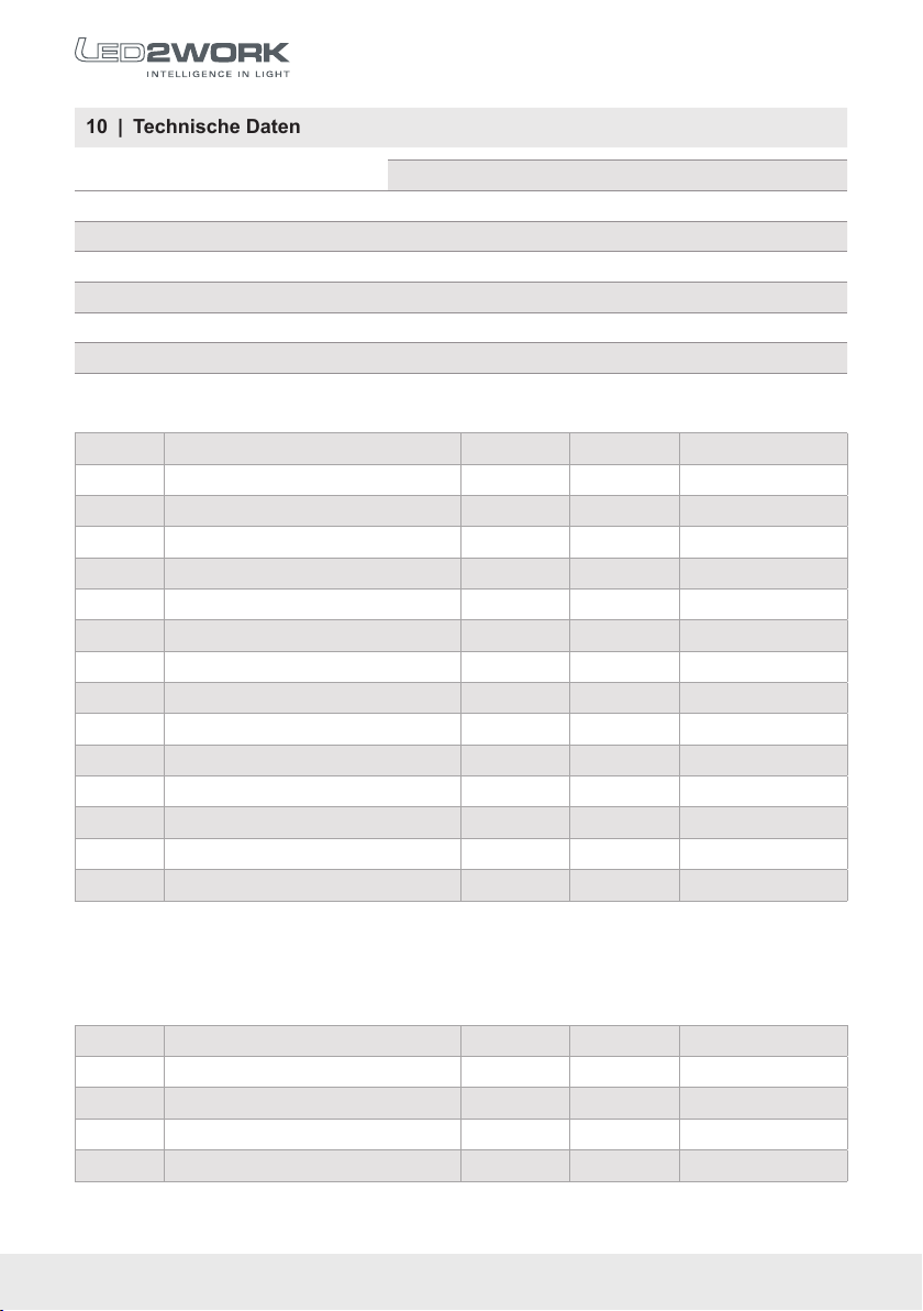
10 | Technische Daten
TUBELED_40 Element DC TUBELED_40 Element AC
Anschlusswerte 24 V DC ±10 % 220 – 240 V~, 50 – 60 Hz
Schutzklasse III I (Schutzerdung)
Lebensdauer LED > 60.000 h > 50.000 h
Betriebstemperatur -30... +70 °C -30... +50 °C
Schutzart IP54 IP54
Techn. Sicherheitsprüfung DIN EN 62471 DIN EN 62471

| 9
TUBELED_40 Element
www.led2work.com
11 | Zeichnung / Drawing
Irrtümer und Änderungen vorbehalten./Errors and technical changes excepted.
TUBELED_40 Element DC
TUBELED_40 Element AC
TUBELED_40 Element DC, kaskadierbar
TUBELED_40 Element DC, cascadable
Buchse / socket
M12 A-kodiert
M12 A-coded
Stecker / plug
M12 A-kodiert
M12 A-coded
Buchse / socket
M12 A-kodiert
M12 A-coded
Buchse / socket
M12 S-kodiert
M12 S-coded
119010-12
119110-12
119210-12
119310-12
119410-12
119510-12
119610-12
119010-02
119110-02
119210-02
119310-02
119410-02
119510-02
119610-02
119110-03
119310-03
119510-03
119610-03

10 | BA TUBELED_40 Element . BA 06/2021
| Contents
1Proper use Page 11
2For safe operation Page 11
3 Safety information Page 12
4Assembly and Mounting Page 12
5Connection Page 10
6Maintenance and Care Page 14
7Warranty Page 15
8Disposal Page 15
9Customer service Page 15
10 Technical data Page 15
11 Drawing Page 9
| Structure of safety and supplementary information
Important instructions are marked with signal words or symbols in this operating manual.
Some signal words denote the degree of the potential risk of injury. Colours and the
different shades of grey and triangular symbols visually underline the degree of danger.
Indicates an imminently hazardous situation which, if not avoided,
will result in death or serious injury.
Indicates a potentially hazardous situation which, if not avoided,
could result in death or serious injury.
Indicates a potentially hazardous situation which, if not avoided,
could result in minor or slight injury.
Indicates a potentially hazardous situation which, if not avoided,
could result in property damage.
Gives you additional information for the safe and efcient use of the
product.
Refers to compliance with these operating instructions.
CE marking: conrms conformity with applicable standards and
regulations.

| 11
TUBELED_40 Element
www.led2work.com
1 | Proper use
The luminaire is used for illumination. The luminaire is intended for mounting in a lumi-
naire holder or mounting bracket.
2 | For safe operation
The operating parameters of the LED luminaire specified on the type plate must cor-
respond to the supply parameters of the machine or of the transformer.
The safety information and all other information in this manual must
be followed. Read the entire operating manual carefully before
mounting and turning on.
Keep the operating manual with the device. It must be stored and
handed over to third parties when the product is passed on.
Machines can emit voltage spikes due to various factors. These
voltage spikes in the power supply via machines should be avoided:
Only use regulated 24V DC switched-mode power supplies, not
transformers with rectifiers, as these can give rise to voltage spikes
due to inductance. Hot plugging should be avoided (connection of
the luminaire to a power supply which is already connected to the
mains), since this can lead to the destruction of the LED luminaire.
Machines or systems can emit voltage spikes due to various
factors. These voltage spikes in the power supply via machines,
systems or units should be avoided:
During the operation of the luminaire in a 220 -240V power supply
net, it could be the cause, that machines (induction perpetrators)
inside the same power supply net cause interference spikes at
start. This deviations may only 10% max.
Under no circumstances may the luminaire be covered with cloths,
foils or similar. Object distance from the luminaire should be at
least 10 cm.
TUBELED_40 Element DC
TUBELED_40 Element AC
Operate the luminaire only in a mounted status.

12 | BA TUBELED_40 Element . BA 06/2021
When mounting the luminaire, make sure that the luminaire is
fastened securely and stably. If the luminaire falls down, its weight
poses a risk of injury!
4 | Assembly and Mounting
Check the LED luminaire before installation to ensure it is complete and shows no
signs of damage. Do not use the luminaire or accessories if they are damaged, as
there is a risk of injury.
The LED luminaire comes fully assembled. Optional there are following mounting ac-
cessories for this luminaire:
Item no.
TUBELED_40 luminaire holder, Aluminium, pair 210200-06
TUBELED_40 luminaire bracket, V2A, pair 210200-11
TUBELED_40 luminaire bracket, V2A, pair, with magnet 210200-12
TUBELED_40 luminaire holder ± 180°, VA, pair 210200-14
Only use the device if it is completely free of faults, and with safety
and awareness in mind.
If warnings or symbols are attached to the luminaire, they must not
be removed.
3 | Safety information
Installation of electrical equipment may only be carried out by quali-
fied electricians.
Follow the five safety rules according to DIN VDE 1005.
Failure to do so may result in damage to the LED luminaire, as well
as fire or other hazards.
Danger of electric shock! Disconnect before working on the
device or load. Ensure to disconnect all circuit breakers that supply
dangerous voltages to the device or load, when doing so. Even
when the device is switched off, the load is not galvanically isolated
from the mains.

| 13
TUBELED_40 Element
www.led2work.com
On the luminaire is an input for an M12 con-
nector A-coded. This socket is used to con-
nect the luminaire with 24V DC fixed voltage,
starting from an operating device.
5 | Connection
Suitable connection material, cables and accessories can be found in the accessory
range of LED2WORK.
Schematic drawing of M12 A-coded
43
12
5
Possible variants of the M12 A-coded
PIN allocation
PIN 1 = 24V DC
PIN 2 = not used
PIN 3 = GND
PIN 4 = 24V DC
PIN 5 = not used
PIN 3 = 0V DC. 24V DC for supply can be connected to PIN 1 or
PIN 4. It is not necessary to assign both PINs (PIN 1 and PIN 4) at
once!
PIN assignment of the M12 connector is as follows:
TUBELED_40 Element DC
Through-wiring (cascadable):
Through-wiring (cascadable) can be used to link several luminaires
electrically to one another.
The total current consumption must not exceed 8 A DC at ta+30°C
max. (or 7 A DC at ta+40°C max.).

14 | BA TUBELED_40 Element . BA 06/2021
6 | Maintenance and Care
The LED luminaire is maintenance-free. Do not make any alterations to the luminaire
(except according to the mounting information contained in this manual).
The luminants used in the luminaire have a very long life and cannot be replaced.
Turn off the light before cleaning and let it cool down completely. Clean the outside of
the luminaire with a soft, dry and clean cloth. To remove excess dirt, moisten the cloth
with water. Never use aggressive cleaning agents, as these may cause discolouration
of the housing.
No liability is assumed for damages resulting from the use of unsuit-
able cleaning agents. The manufacturer is also not liable for direct
or indirect consequential damage caused by unauthorized interven-
tion in the luminaire.
TUBELED_40 Element AC: The internal power supply unit may
only be changed by qualified personnel. No warranty is given for
power supplies unit not approved by the manufacturer.
TUBELED_40 Element AC
On the luminaire is an input for about a M12 connector S-coded. About this jack and
with suitable connection material the luminaire is connected with a 230V AC electric
power supply system.
For the installation on the power supply system the luminaire must
be electrically load-free. A direct connection of a luminaire via a
running machine can destroy the LEDs!
PIN assignment of the M12 connector is as follows:
PIN allocation
PIN 1 = not connected brown
PIN 2 = external conductor/
phase (L)
black
PIN 3 = neutral conductor (N) gray
PIN 4 = protective earth
conductor (PE)
green/
yellow
Schematic drawing of M12 S-coded
4
1
2
3

| 15
TUBELED_40 Element
www.led2work.com
10 | Technical data
TUBELED_40 Element DC TUBELED_40 Element AC
Connection values 24 V DC ±10 % 220 – 240 V~, 50 – 60 Hz
Class of protection III I (protective grounding)
LED lifetime > 60.000 h > 50.000 h
Operating temperature -30... +70 °C -30... +50 °C
System of protection IP54 IP54
Technical safety inspection DIN EN 62471 DIN EN 62471
7 | Warranty
We supply a full warranty for the product for 36 months from the date of purchase. This
warranty applies for fault-free working under proper use and in accordance with the
operating instructions.
During the warranty period defects and faults in the product will be rectified free of
charge if they are proven to be caused by material, processing or design errors. If the
purchaser complains of a material defect, he bears the burden of proof to demonstrate
that the product was already defective upon receipt.
The warranty does not extend to defects caused by wear, negligen-
ce or improper use.
Further claims, in particular claims for compensation for damage
that did not occur on the LED luminaire itself, are excluded.
8 | Disposal
The luminaire must be disposed of at a suitable
disposal site designated for recycling of electrical and
electronic equipment in accordance with local, nation-
al regulations. (WEEE-Nr. 32828318)
9 | Customer service
If you have any problems or questions concerning this product, please contact us!
By phone: +49 7231 44920-00
Monday to Thursday 8:00 am to 12:00 midday and 1:00 pm to 4:30 pm
Friday 8:00 am to 12:00 midday and 1:00 pm to 3:00 pm
By email: info@led2work.com

Leuchte gefertigt am / Date of production _________________________
© LED2WORK GmbH BA 06/2021 . 8960-2240-00-000 . BA TUBELED_40 Element
LED2WORK GmbH
Stuttgarter Str. 13 A
75179 Pforzheim | Germany
T +49 7231 44920-00
www.led2work.com
Irrtümer und Änderungen vorbehalten./Errors and technical changes excepted.
TUBELED_40 Element 24V DC, 5200K-5700K
Item no. LED luminaire Length
Beam angle
Max. power cons.
119010-02 TUBELED_40 Element DC 190 mm 100° 4 W
119010-12 TUBELED_40 Element DC, kaskadierbar* 190 mm 100° 4 W
119110-02 TUBELED_40 Element DC 280 mm 100° 6 W
119110-12 TUBELED_40 Element DC, kaskadierbar* 280 mm 100° 6 W
119210-02 TUBELED_40 Element DC 365 mm 100° 8,5 W
119210-12 TUBELED_40 Element DC, kaskadierbar* 365 mm 100° 8,5 W
119310-02 TUBELED_40 Element DC 540 mm 100° 13 W
119310-12 TUBELED_40 Element DC, kaskadierbar* 540 mm 100° 13 W
119410-02 TUBELED_40 Element DC 715 mm 100° 17 W
119410-12 TUBELED_40 Element DC, kaskadierbar* 715 mm 100° 17 W
119510-02 TUBELED_40 Element DC 1040 mm 100° 24 W
119510-12 TUBELED_40 Element DC, kaskadierbar* 1040 mm 100° 24 W
119610-02 TUBELED_40 Element DC 1540 mm 100° 38 W
119610-12 TUBELED_40 Element DC, kaskadierbar* 1540 mm 100° 38 W
*cascadable: through-wiring can be used to link several luminaires electrically to one another. The total current consumption
must not exceed 8A DC at ta +30°C max. or 7 A DC at ta +40°C max.
TUBELED_40 Element 230V AC, 5200K-5700K
Item no. LED luminaire Length
Beam angle
Max. power cons.
119110-03 TUBELED_40 Element AC 280 mm 100° 8,5 W
119310-03 TUBELED_40 Element AC 540 mm 100° 17 W
119510-03 TUBELED_40 Element AC 1040 mm 100° 34 W
119610-03 TUBELED_40 Element AC 1540 mm 100° 51 W
Other manuals for TUBELED 40 Element DC
1
This manual suits for next models
19
Table of contents
Languages:
Other LED2WORK Lighting Equipment manuals

LED2WORK
LED2WORK INROLED 70 AC User manual

LED2WORK
LED2WORK TUBELED 40 Element DC User manual

LED2WORK
LED2WORK INROLED 70 DC User manual

LED2WORK
LED2WORK TUBELED-70 DC User manual

LED2WORK
LED2WORK CENALED SPOT Flexarm User manual

LED2WORK
LED2WORK SPOTLED II User manual

LED2WORK
LED2WORK TUBELED-25 User manual

LED2WORK
LED2WORK UNILED II User manual

LED2WORK
LED2WORK TUBELED 40 II Series User manual

LED2WORK
LED2WORK TUBELED_40 II User manual