Lega DV4 Series User manual

LEGA srl Costruzioni Apistiche –via Maestri del Lavoro 23 –48018 Faenza
www.legaitaly.com - Tel 054626834 –Fax 054628279 –P.iva 00043230390
manuale d’istruzioni
Instruction manual / Guide d'instructions / Bedienungsanleitung
Code
4300
4301
Matr
Rev
20180330
IT
Disopercolatrice DV4 - DB - Langst
2
EN
DV4 Professional uncapping machine - DB - Langst
9
FR
Machine à désoperculer DV4 - DB - Langst
16
DE
Entdecklungsmaschine DV4 - DB - Langst
23

LEGA srl Costruzioni Apistiche –via Maestri del Lavoro 23 –48018 Faenza
www.legaitaly.com - Tel 054626834 –Fax 054628279 –P.iva 00043230390
2 / 36
La ditta costruttrice non si riterrà responsabile d’inconvenienti, rotture o incidenti dovuti al
mancato rispetto o alla non applicazione delle indicazioni contenute nel presente manuale.
1.0 AVVERTENZE GENERALI SULLA SICUREZZA
LEGGERE ATTENTAMENTE QUESTO MANUALE PRIMA D’UTILIZZARE LA MACCHINA
Questo libretto e' parte integrante della macchina e l'accompagna fino alla demolizione.
La macchina presenta parti pericolose perché allacciata alla rete elettrica e dotata di movimento, pertanto
possono causare gravi danni a persone o cose:
- un uso improprio
- la rimozione delle protezioni e lo scollegamento dei dispositivi di protezione
- la mancanza d’ispezioni e manutenzioni
- la manomissione dell’impianto elettrico
Le istruzioni devono essere integrate ed aggiornate in base alle disposizioni legislative e dalle norme tecniche
di sicurezza vigenti.
1.1 IDENTIFICAZIONE DELLA MACCHINA
Disopercolatrice per il taglio dell’opercolo in favi (nominati in questo manuale anche come telaini) da melario
D.B. standard e Langstroth, con o senza distanziatore modello Hoffmann, tramite l’utilizzo di coltelli a lame
dentate oscillanti e riscaldate elettricamente, con avanzamento su catena, velocità di avanzamento regolabile.
1.2 DATI TECNICI
Art. 4300 Disopercolatrie DV4 D.B.
Caratteristiche Tecniche
Telaini disopercolati min
Nr / H
400
Telaini disopercolati max
Nr / H
800
Assorbimento totale
w
2000
Tensione di alimentazione
V
220
Peso
Kg
125
Ingombro massimo
mm
1150x1050x1370
Art. 4301 Disopercolatrie DV4 Langstroth
Caratteristiche Tecniche
Telaini disopercolati min
Nr / H
300
Telaini disopercolati max
Nr / H
600
AssorbimentoTotale
w
2000
Tensione di alimentazione
V
220
Peso
Kg
125
Ingombro massimo
mm
1150x1050x1370

LEGA srl Costruzioni Apistiche –via Maestri del Lavoro 23 –48018 Faenza
www.legaitaly.com - Tel 054626834 –Fax 054628279 –P.iva 00043230390
3 / 36
ATTENZIONE! ai fini della sicurezza questa macchina deve essere utilizzata esclusivamente da
personale adulto il quale deve essere informato delle istruzioni contenute in questo manuale, che
costituisce parte integrante ed essenziale della macchina.
1.3 PERSONALE ADDETTO
La disopercolatrice è studiata per l’utilizzo da parte di una sola persona.
Una conoscenza di base di tecnica meccanica serve per un corretto svolgimento del lavoro, per effettuare le
manutenzioni e, in caso d’inconvenienti elementari.
1.4 AVVERTENZE / USO PREVISTO E NON PREVISTO
Per un buon rendimento della macchina, lo spessore del legno dei telaini deve essere costante ed è consigliato
l’uso dei distanziatori nei melari.
I telaini non devono presentare sporgenze laterali come chiodi.
Si consiglia di utilizzare melari con distanziatori con almeno una tacca in meno del nominale dell’arnia (es. per
un’arnia a 10 favi, melari con 9 favi o meglio ancora 8 favi).
Questa macchina deve essere impiegata esclusivamente per la disopercolatura di favi.
1.5 MOVIMENTAZIONE / TRASPORTO
La disopercolatrice non può essere sollevata o trasportata manualmente da una sola persona, il trasporto può
essere effettuato con macchina “a vista” o in imballi particolari (es. cassa in legno).
Il trasporto viene normalmente effettuato da trasportatori, sotto la responsabilità del cliente.
Durante il trasporto la cassa contenente la macchina deve essere solidamente fissata con funi o cinghie in
modo da impedirne il movimento.
La macchina è spostabile tramite muletto o trans pallet.
Il peso della macchina è circa 125 kg, i mezzi di sollevamento devono pertanto essere adeguati a sopportare
questo peso.
DURANTE LA MOVIMENTAZIONE DELLA MACCHINA PROCEDERE MOLTO LENTAMENTE!

LEGA srl Costruzioni Apistiche –via Maestri del Lavoro 23 –48018 Faenza
www.legaitaly.com - Tel 054626834 –Fax 054628279 –P.iva 00043230390
4 / 36
2.0 ISTRUZIONI D’USO
E
D
C
B
A
FIG. 1 - Quadro elettrico comandi
FIG. 2 - Quadro elettrico generale
G
F

LEGA srl Costruzioni Apistiche –via Maestri del Lavoro 23 –48018 Faenza
www.legaitaly.com - Tel 054626834 –Fax 054628279 –P.iva 00043230390
5 / 36
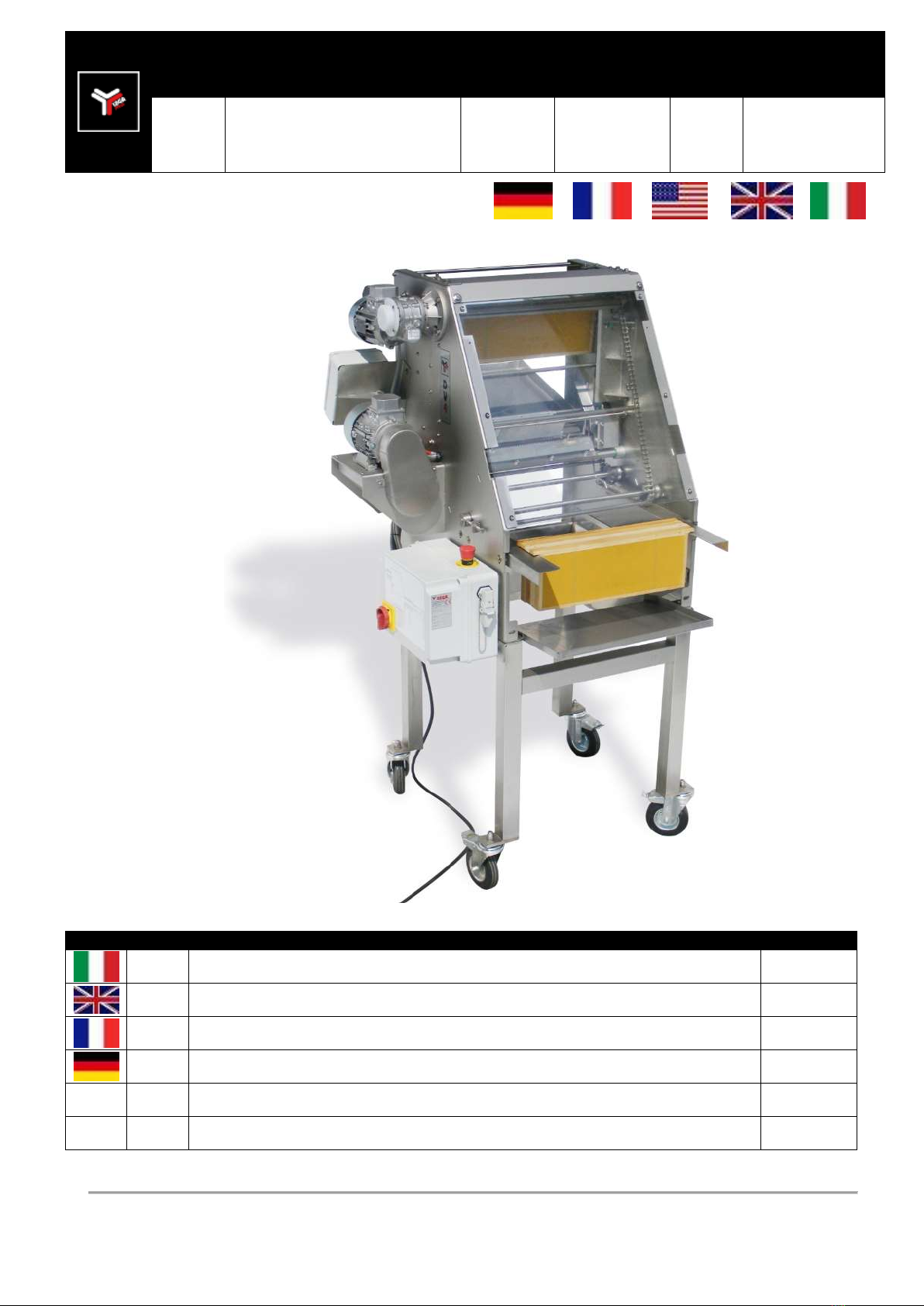
La disopercolatrice è fornita di due quadri elettrici, il quadro elettrico generale (fig.2) è posto sul fianco destro
della macchina, quello comandi (fig.1) è posto in posizione frontale, comoda per l’operatore.
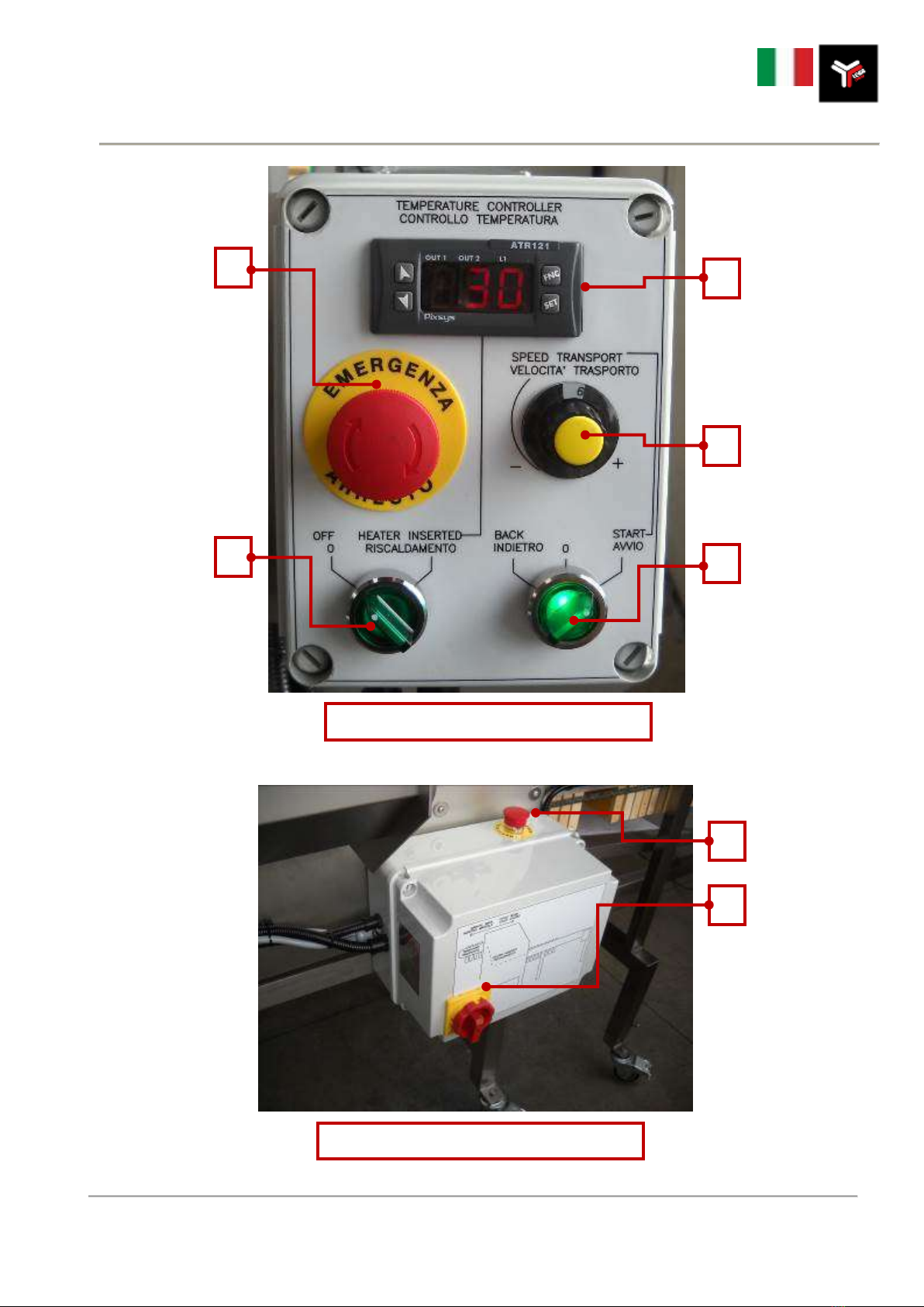
Prima di collegare la disopercolatrice alla corrente elettrica è necessario accertarsi che l’interruttore generale
(fig. 2 punto G) sia in posizione di ‘O’.
Allacciare la disopercolatrice DV4 alla presa di corrente.
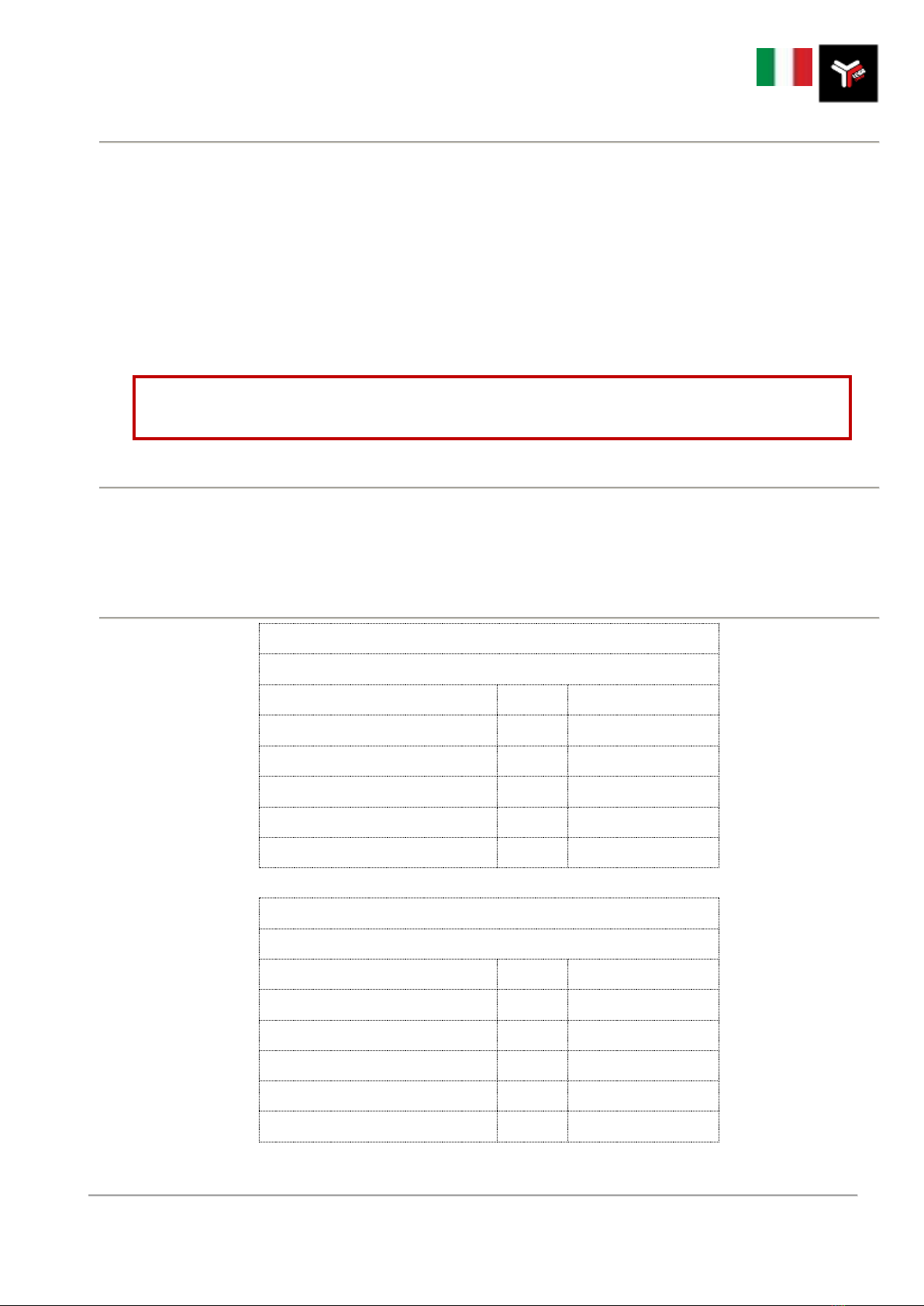
Assicurarsi che il fungo d’emergenza (fig. 1-A) e quello nel quadro generale (fig. 2-F) non sia inserito, quindi
ruotare l’interruttore generale (fig. 2-G) in posizione ‘1’.
Regolare il termostato (fig. 1-E) come spiegato nel paragrafo ‘2.1
Istruzioni per l’uso del termoregolatore’ del presente manuale.
La temperatura impostata di default, che noi riteniamo essere corretta
è di 80/90°C.
Accendere il riscaldamento dei coltelli tramite il selettore
‘Riscaldamento’ (fig. 1-B) e attendere alcuni istanti per permettere ai
coltelli di raggiungere la temperatura impostata.
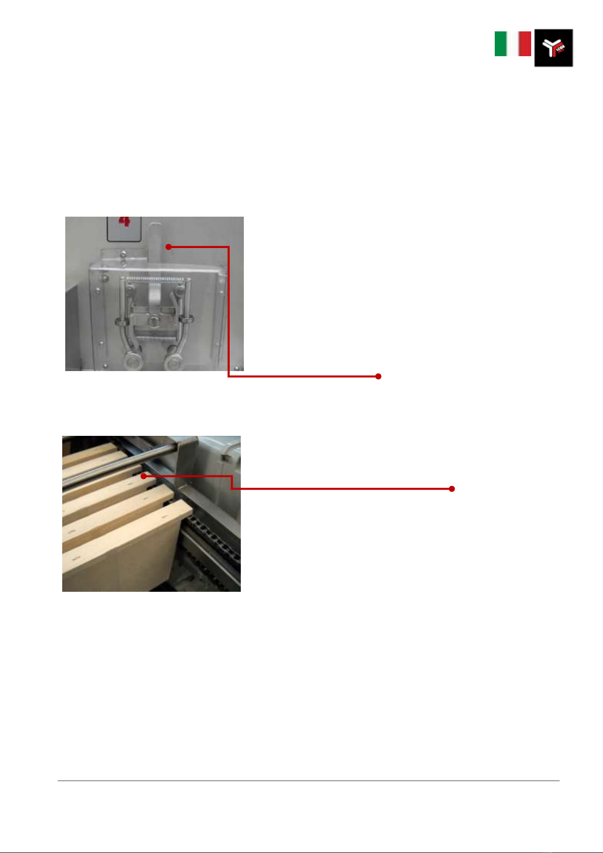
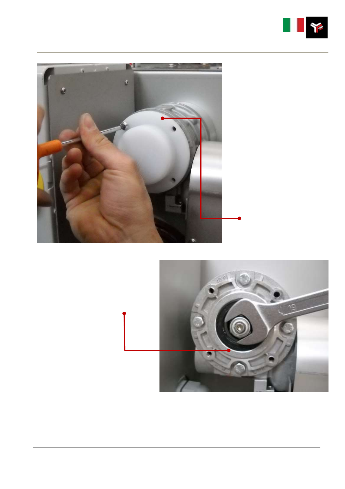
Per regolare l’apertura dei coltelli è necessario agire sulla leva.
La leva può servire anche per allargare i coltelli in caso di emergenza per sbloccare l’eventuale telaino
incastrato.
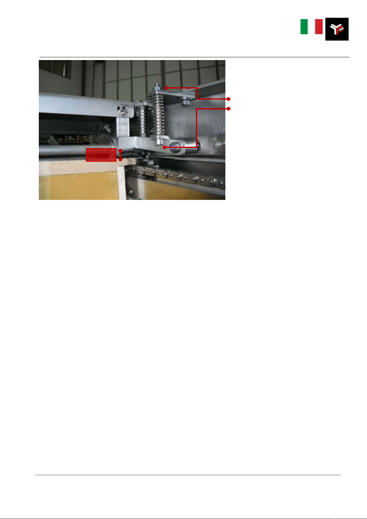
Posizionare i telaini sulla catena (ferma), perpendicolarmente alla
catena stessa, far scorrere la catena verso l’entrata della macchina in
modo da poter aggiungere circa 9/10 telaini.
Ruotare il selettore (fig. 1-C) verso destra, in posizione Start per fare
avanzare la catena e i coltelli.
E’ chiaramente possibile caricare i telaini anche dopo aver avviato la
disopercolatrice, ovvero con la catena in movimento, in modo continuo.
Nel caso un telaino si blocchi, ruotare il selettore (fig. 1-C) in posizione centrale per fermare l’avanzamento della catena.
È possibile far ruotare la catena in senso contrario, ruotando il selettore (fig. 1-C) verso sinistra, funzione ad impulsi.
A termine delle lavorazioni è necessario togliere corrente, ruotando l’interruttore generale (fig. 2-G) in posizione
‘0’.
In caso di pericolo premere il tasto d’emergenza (fig. 1-A oppure fig. 2-F).
L’arresto d’emergenza prevale su tutte le altre funzioni ed operazioni.

LEGA srl Costruzioni Apistiche –via Maestri del Lavoro 23 –48018 Faenza
www.legaitaly.com - Tel 054626834 –Fax 054628279 –P.iva 00043230390
6 / 36
ATTENZIONE! Le operazioni di manutenzione vanno eseguite a macchina ferma e a collegamenti
elettrici disinseriti.
ATTENZIONE!
1) Durante il lavaggio prestare la massima attenzione alle lame dei coltelli;
2) Non indirizzare getti d’acqua verso le parti elettriche.
2.1 ISTRUZIONI PER L’USO DEL TERMOREGOLATORE
Il termoregolatore, posto sul quadro comandi, presenta quattro pulsanti e un quadrante a display.
Il display, dopo aver collegato la DV4 alla rete, ed aver atteso per alcuni secondi, indica la temperatura dei
coltelli.
Premendo il pulsante SET viene indicata la temperatura prescelta quale massima raggiungibile.
Per variare questa temperatura premere il pulsante SET (C) e successivamente premere il pulsante con la
freccia rivolta (A) in alto per aumentare i gradi o quello con la freccia rivolta in basso (B) per diminuirli.
3.0 MANUTENZIONE
Non si ritengono necessari particolari lavori di manutenzione.
La macchina va lavata con acqua tiepida ed eventualmente con detergenti neutri commerciali appositi per
l’acciaio inox.
Evitare assolutamente di lavare la macchina con attrezzature che utilizzino il vapore.
Se si prevede che la macchina debba rimanere inutilizzata per parecchio tempo, provvedere a verificare la
stato dei componenti meccanici ad eventuali lavori di revisione, sostituzione o manutenzione per avere la
macchina nelle migliori condizioni per l'utilizzo successivo.
Per un periodo di lunga inattività è consigliabile ungere con un velo d'olio di paraffina le parti cromate e
ricoprire la macchina con un telo.
C
A
B

LEGA srl Costruzioni Apistiche –via Maestri del Lavoro 23 –48018 Faenza
www.legaitaly.com - Tel 054626834 –Fax 054628279 –P.iva 00043230390
7 / 36
3.1 REGOLAZIONE DELLA FRIZIONE
La regolazione della frizione è
un’operazione estremamente
semplice e permette di calibrare al
meglio, a seconda delle esigenze di
ogni singolo operatore, la forza
trainante della catena porta telaino.
Una frizione troppo ‘stretta’ potrebbe
creare qualche problema rischiando di
spaccare alcuni telaini al passaggio
tra i coltelli. D’altra parte, una frizione
troppo ‘blanda’ impedirebbe la
disopercolatura perché il telaino si
fermerebbe alla prima difficoltà.
Tramite una chiave a brugola di 4,
svitare le 4 viti che fissano la
protezione rotonda in teflon, posta
dietro al quadro comandi.
Con una chiave fissa, svitare o avvitare il
dado autobloccante fino al raggiungimento
della calibrazione gradita.
Rimontare il carter prima di mettere
nuovamente in funzione la macchina.

LEGA srl Costruzioni Apistiche –via Maestri del Lavoro 23 –48018 Faenza
www.legaitaly.com - Tel 054626834 –Fax 054628279 –P.iva 00043230390
8 / 36
3.2 REGOLAZIONE DEL PRESELETTORE
E’ necessario che tra il pettine dentato e
la sommità del portafavo ci sia uno
spazio pari a circa 5 mm.
Per regolare il selettore, allentare il
controdado in alto e, tramite una chiave
a brugola avvitare o svitare la vite
verticale.
Una volta trovata la giusta dimensione,
fissare nuovamente il tutto serrando il
controdado.
5 mm

LEGA srl Costruzioni Apistiche –via Maestri del Lavoro 23 –48018 Faenza
www.legaitaly.com - Tel 054626834 –Fax 054628279 –P.iva 00043230390
9 / 36
4.0 IMPIANTO ELETTRICO 220V

LEGA srl Costruzioni Apistiche –via Maestri del Lavoro 23 –48018 Faenza
www.legaitaly.com - Tel 054626834 –Fax 054628279 –P.iva 00043230390
10 / 36
The manufacturer may not be held responsible for failures, breaks or accidents resulting from
incorrect use of the machine or failure to follow the directions contained in this manual.
1.0 GENERAL SAFETY DIRECTIONS
READ THIS MANUAL THROUGHOUT BEFORE USING THE MACHINE
This handbook forms an integral part of the machine and should be kept with it throughout its working life.
The machine includes dangerous electrically live and moving parts, which can cause serious damages to
persons or property in case of:
- incorrect use
- removal of guards or disconnection of safety devices
- poor inspection and servicing
- tampering with the electric system
These directions must be completed and updated according to applicable legal provisions and technical safety
standards.
1.1 IDENTIFICATION OF THE MACHINE
Uncapping machine designed for cutting of cappings in D.B. standard and Langstroth frames (also referred to
as super frames/supers) with or without a Hoffmann spacer, by using electrically heated serrated knives on a
chain conveyor with adjustable speed.
1.2 TECHNICAL SPECIFICATIONS
Art. 4300 Uncapping Machine DV4 D.B.
Technical Specifications
220V
110V
Uncapped frames min
N/h
400
400
Uncapped frames max
N/h
800
800
Total Absorption
w
2000
2000
Input voltage
V
220
110
Weight
Kg
125
125
Overall dimensions
mm
1150x1050x1370
1150x1050x1370
Art. 4301 Uncapping Machine DV4 Langstroth
Technical Specifications 220V
110V
Uncapped frames min
N/h
300
300
Uncapped frames max
N/h
600
600
Total Absorption
w
2000
2000
Input voltage
V
220
110
Weight
Kg
125
125
Overall dimensions
mm
1150x1050x1370
1150x1050x1370

LEGA srl Costruzioni Apistiche –via Maestri del Lavoro 23 –48018 Faenza
www.legaitaly.com - Tel 054626834 –Fax 054628279 –P.iva 00043230390
11 / 36
CAUTION! for safety purposes, this machine should be used by skilled staff only, aware of the
instructions contained in this manual which forms an integral part of the machine.
1.3 MACHINE OPERATORS
The uncapping machine has been designed for operation by a single worker.
Basic technical and mechanical skills are required to correctly operate the machine and carry out maintenance
and basic servicing.
1.4 DIRECTIONS / RECOMMENDED AND NOT RECOMMENDED USE
For efficient machine operation, the frame wood thickness must be constant and the use of spacers in the
supers is recommended.
The frames should not have any protruding parts e.g. nails.
We recommend using supers with spacers at least one notch down from the hive frame number (e.g. for a 10-
frame beehive, use supers with 9 frames or better still, 8 frames).
This machine should be exclusively used for the uncapping of frames.
1.5 HANDLING / TRANSPORT
The uncapping machine cannot be lifted or handled manually by a single person. The machine can be
transported unpacked or in suitable packing (e.g. wooden crate).
Transport is normally carried out by appointed forwarders on the customer's own responsibility.
During transport, the crate containing the machine must be firmly secured with ropes or cables to prevent it
moving.
The machine can be handled by using lift trucks or pallet trucks.
The machine weight is approximately 125 kg, therefore, the lifting equipment must be of adequate carrying
capacity.
PROCEED VERY SLOWLY WHEN HANDLING THE MACHINE.

LEGA srl Costruzioni Apistiche –via Maestri del Lavoro 23 –48018 Faenza
www.legaitaly.com - Tel 054626834 –Fax 054628279 –P.iva 00043230390
12 / 36
2.0 OPERATING INSTRUCTIONS
E
D
C
B
A
FIG. 1 –Operating control panel
FIG. 2 –Main control panel
G
F

LEGA srl Costruzioni Apistiche –via Maestri del Lavoro 23 –48018 Faenza
www.legaitaly.com - Tel 054626834 –Fax 054628279 –P.iva 00043230390
13 / 36
The uncapping device is provided with two control panels, the main control unit (fig.2) is placed on the right
side of the machine, the operating panel (fig.1) is placed in the front position, convenient for the operator.
Before plugging the uncapping machine into a line power socket, make sure that the main switch (fig. 2 - G) is
set to 'O'.
Plug the DV4 uncapping machine into a power socket.
Make sure that the mushroom-head emergency button (fig. 1-A) and the switch on the main control panel (fig.
2-F) have not been operated, then turn the main switch (fig. 2 - G) to ‘0’.
Set the thermostat (fig. 1-E) as illustrated in paragraph '2.1
Instructions for thermoregulator use' of this manual.
The default temperature setting - which on average has been found
correct - is 80/90°C.
Control knife heating by actuating the selector switch ‘Heating’ (fig. 1
- B) then wait a few seconds to allow the knives to heat up to the pre-
set temperature.
To adjust the knives, operate on the lever.
The lever could also serve to widen the knives in case of emergency, to release a frame which got stuck.
Place the frames on the (stationary) chain perpendicularly to the chain
(fig. 3) and cause the chain to run towards the machine inlet so that
9/10 frames can be added.
Turn the selector switch (Fig. 1-C) to the right, in its ‘Start’ position, to
control the forward movement of the chain and the knives.
It is also possible to load the frames when the uncapping machine has
been started, i.e. when the chain is moving, in a continuous manner.
If a frame gets stuck, turn the selector switch (fig. 1 - C) to a central position to stop the chain.
It is possible to rotate the chain in the opposite direction, by rotating the selector switch (fig. 1-C) to the left,
for pulse operation.
At the end of the work you must disconnect the machine by turning the main switch (fig. 2-G) to position '0'.
In case of danger, hit the emergency button (fig. 1 item A or fig. 2 item F).
The emergency stop shall prevail over all other functions and operations.

LEGA srl Costruzioni Apistiche –via Maestri del Lavoro 23 –48018 Faenza
www.legaitaly.com - Tel 054626834 –Fax 054628279 –P.iva 00043230390
14 / 36
CAUTION! Maintenance operations should be carried out after stopping the machine and
disconnecting electric power.
CAUTION!
1) Be extremely careful when handling the knife blades, e.g. during washing
2) Do not direct water jets towards electrical parts.
2.1 INSTRUCTIONS FOR THERMOREGULATOR USE
The thermoregulator located on the control panel has four keys and a display unit.
After connecting the DV4 machine to line power and waiting a few seconds, check the display unit for the knife
temperature reading.
Press the SET button to display the maximum selected temperature setting.
To change this temperature setting, press the SET (C) control then press the button with the arrow pointing up
(A) to increase the temperature degree value or the button with the arrow pointing down (B) to decrease it.
3.0 MAINTENANCE
No special maintenance is required.
The machine should be washed with warm water and mild detergents of the type commercially available for
stainless steel, if necessary.Do not in any case clean the machine with steam jets.
If you expect not to use the machine for a prolonged period of time, check the state of repair of its mechanical
parts and carry out any required checking, replacement or maintenance to ensure that the machine will be
ready for use upon the next power-on.
Before periods of prolonged inactivity, coat the chromium plated parts of the machine with a thin film of
paraffin oil and then cover the machine with a tarpaulin.
C
A
B

LEGA srl Costruzioni Apistiche –via Maestri del Lavoro 23 –48018 Faenza
www.legaitaly.com - Tel 054626834 –Fax 054628279 –P.iva 00043230390
15 / 36
3.1 CLUTCH ADJUSTMENT
Adjusting the clutch is an extremely
easy operation enabling to calibrate in
an ideal way, according to different
operator requirements, the pulling
force of the frame conveyor chain.
Too 'tight' a clutch adjustment may
cause problems and could even break
some frames when they are fed on
between blades. Conversely, too
'loose' a clutch adjustment would
prevent uncapping as the frame would
stop every time that even a minor
obstacle is encountered.
By using a size 4 Allen wrench, undo
the 4 screws securing the round
teflon guard on the rear of the control
panel.
By using a spanner, unlock the lock nut and
tighten or loosen the nut until the right
adjustment is obtained. Then replace the
guard before restarting the machine.

LEGA srl Costruzioni Apistiche –via Maestri del Lavoro 23 –48018 Faenza
www.legaitaly.com - Tel 054626834 –Fax 054628279 –P.iva 00043230390
16 / 36
3.2 ADJUSTMENT OF PRESELECTOR
It is necessary that there is a space
equal to around 5 mm. between the
toothed comb and the summit of the
outer cover.
To regulate the selector, you have to
loosen the locknut up and you screw or
unscrew the vertical grapevine through
a tire iron
When you find the correct dimension,
shut the locknut to fix all again.
5 mm

LEGA srl Costruzioni Apistiche –via Maestri del Lavoro 23 –48018 Faenza
www.legaitaly.com - Tel 054626834 –Fax 054628279 –P.iva 00043230390
17 / 36
4.0 ELECTRIC SYSTEM 220V

LEGA srl Costruzioni Apistiche –via Maestri del Lavoro 23 –48018 Faenza
www.legaitaly.com - Tel 054626834 –Fax 054628279 –P.iva 00043230390
18 / 36
1.0 RECOMMANDATIONS GÉNÉRALES SUR LA SÉCURITÉ
LIRE ATTENTIVEMENT CE GUIDE AVANT D'UTILISER LA MACHINE
Ce guide fait partie intégrante de la machine et l'accompagne jusqu'à sa démolition.
La machine présente des parties dangereuses car elle est branchée au réseau électrique et comprend des
organes en mouvement, elle peut donc causer de graves dommages aux personnes ou aux biens dans les
situations suivantes :
- une utilisation impropre ;
- le retrait des protections et le débranchement des dispositifs de protection ;
- le manque d'inspections et de maintenance;
- la modification de l'installation électrique.
Les instructions doivent être complétées et actualisées en fonction des dispositions législatives et des normes
techniques de sécurité en vigueur.
Le constructeur ne sera aucunement responsable en cas de problèmes, ruptures ou accidents dus au non-respect
ou à la non-application des recommandations contenues dans ce guide.
1.1 IDENTIFICATION DE LA MACHINE
Machine à désoperculer pour la coupe de l'opercule en rayons (également appelés « cadres » dans ce guide)
de hausse D. B. standard et Langstroth, avec ou sans écarteur modèle Hoffmann, au moyen de couteaux à
lames dentées vibrantes et chauffées électriquement et de rouleaux, avec avancement sur chaîne, vitesse
d’avance réglable.
1.2 DONNÉES TECHNIQUES
Art. 4300 Machine à désoperculer DV4 D.B.
Caractéristiques techniques
Cadres désoperculés min.
Nr / H
400
Cadres désoperculés max.
Nr / H
800
Absorption totale
w
2000
Tension d'alimentation
V
220
Poids
kg
125
Encombrement maximum
mm
1150x1050x1370
Art. 4301 Machine à désoperculer DV4 Langstroth
Caractéristiques techniques
Cadres désoperculés min.
Nr / H
300
Cadres désoperculés max.
Nr / H
600
Absorption totale
w
2000
Tension d'alimentation
V
220
poids
kg
125
Encombrement maximum
mm
1150x1050x1370

LEGA srl Costruzioni Apistiche –via Maestri del Lavoro 23 –48018 Faenza
www.legaitaly.com - Tel 054626834 –Fax 054628279 –P.iva 00043230390
19 / 36
1.3 PERSONNEL PRÉPOSÉ
ATTENTION ! AFIN DE GARANTIR LA SÉCURITÉ, CETTE MACHINE DOIT ÊTRE UTILISÉE EXCLUSIVEMENT
PAR DU PERSONNEL ADULTE QUI DOIT ÊTRE À CONNAISSANCE DES INSTRUCTIONS CONTENUES DANS
CE GUIDE, QUI CONSTITUE UNE PARTIE INTÉGRANTE ET ESSENTIELLE DE LA MACHINE.
La machine à désoperculer a été conçue pour être utilisée par une seule personne.
Une connaissance de base en mécanique est utile pour exécuter correctement le travail, effectuer les
opérations de maintenance et en cas de problèmes élémentaires.
1.4 AVERTISSEMENTS/UTILISATION PRÉVUE ET NON PRÉVUE
Pour un bon rendement de la machine, l'épaisseur du bois des cadres doit être constante; il est conseillé
d'utiliser des écarteurs dans les hausses.
Les écarteurs ne doivent pas présenter de saillies latérales tels que des clous.
Il est conseillé d'utiliser des hausses avec des écarteurs avec au moins une encoche de moins que le nombre
nominal de la ruche (ex.: pour une ruche à 10 cadres, des hausses de 9 cadres ou mieux encore 8 cadres).
Cette machine doit être exclusivement utilisée pour la désoperculation de cadres.
1.5 MANUTENTION/TRANSPORT
La machine à désoperculer ne peut être ni soulevée ni transportée manuellement par une seule personne, le
transport peut être effectué avec la machine emballée (par ex. dans une caisse de bois) ou sans emballage.
Le transport est normalement effectué par des transporteurs, sous la responsabilité du client.
Durant le transport la caisse contenant la machine doit être solidement fixée avec des câbles ou des courroies
de façon à ce qu'elle ne bouge pas.
La machine peut être déplacée avec un chariot élévateur ou un transpalette
Le poids de la machine est d'environ 125 kg, les moyens de levage doivent donc être adaptés à supporter ce
poids.
DURANT LA MANUTENTION DE LA MACHINE PROCÉDER LENTEMENT !

LEGA srl Costruzioni Apistiche –via Maestri del Lavoro 23 –48018 Faenza
www.legaitaly.com - Tel 054626834 –Fax 054628279 –P.iva 00043230390
20 / 36
2.0 INSTRUCTIONS D’UTILISATION
E
D
C
B
A
FIG. 1 Tableau de commandes
FIG. 2 - tableau électrique générale
G
F
Other manuals for DV4 Series
1
This manual suits for next models
2
Table of contents
Languages:
Other Lega Packaging Equipment manuals
Popular Packaging Equipment manuals by other brands

Berran Industrial Group
Berran Industrial Group Eagle SP11 Use, maintenance and spare parts manual

Fromm
Fromm FSW10 Operation manual

Highlight
Highlight PREDATOR XS Operation manual

deffner & Johann
deffner & Johann HornPac Quick manual

Orgapack
Orgapack OR-T 130 quick guide

U-Line
U-Line H-167 quick start guide

HAITEC
HAITEC HT-KJ20 Series Quick start manual

Brugg Pipesystems
Brugg Pipesystems CALPEX instruction manual

Pregis
Pregis Easypack Quantum XT operating manual

strapex
strapex SMA 30 operating instructions

Fromm
Fromm P322 Operation manual & spare parts list

Rotochopper
Rotochopper Go-Bagger 250 quick start guide