IDS VL-HP User manual

U.S. TAX STAMPING
EQUIPMENT
Manufactured by United Silicone an ITW Company
VL-HP VALUE LINE
SERVICE & OPERATION MANUAL
April 13
Version 2


Page 3 of 68
VL-HP Service
& Operation Manual
U.S. TAX STAMPING
EQUIPMENT
Manufactured by United Silicone
an ITW company
Table of Contents Page
1.0 Introduction 4
2.0 Overview of operations 5
2.1 Carton trough Assembly 7
2.1.1 Rear surface plate 7
2.1.2 Front door plates 7
2.1.3 Carton float springs 8
2.1.4 Carton drive assembly 8
2.1.5 Ceiling top devices 9
2.1.5.1 Lift station top plate 9
2.1.5.2 Opener horn 9
2.1.5.3 Flap detection 10
2.1.5.4 Stamper top plate 10
2.1.5.5 Small flap closer mechanism 11
2.1.5.6 Large flap closer mechanism 11
3.0 Powering Up 12
3.1. Electrical 12
3.2. Air 13
3.2.1 Moisture 14
4.0 Tax Stamps 15
4.1. Cartridge Loading 16
5.0 Run Mode 19
5.1. Machine Emergency Stop 19
5.2. Machine Homing 19
5.3. Starting Auto Cycle 19
5.3 Stopping the Stamp Machine 20
6.0 Glue System 21
7.0 Stamping Cigarettes 22
8.0 Operator Controls 23
8.0.1 Screen banner functions 24
8.1.0 Main Screen 25
8.1.1 Main Menu Screen 26
8.1.1.1 Order Review Screen
8.1.1.2 Glue Screen
8.1.2 Stamp Setup Screen 27
8.1.3 Temperature Setup 28
8.1.4 Pre Heat 29
8.1.5 Statistics 30
8.1.6 Current Alarm Screen 31
8.1.7. Supervisor Screen 32
8.2.1. Index Setup 34
8.2.2. Alarm History 35
8.2.3. Date and Time 36
8.2.4. Sensor and Valve Status 37

Page 4 of 68
VL-HP Service
& Operation Manual
U.S. TAX STAMPING
EQUIPMENT
Manufactured by United Silicone
an ITW company
9.0 In-feed Table 38
9.1 In-feed Tip-Over Sensing 38
10.0 In-feed Carton Lift 38
11.0 Carton Opener 39
12.0 Flap Detection 40
13.0 Stamp Head 40
13.1 Carton Support 41
13.2 Shifting Between Lanes of Stamps on the Stamp Roll 42
13.3 Stamp Paper Advancement 43
13.3.1 Laser Sensors
13.3.2 Adjusting the Primary Laser Sensors 45
13.3.3 Adjusting the Secondary Laser Sensors 45
14.0 Closing Section 46
14.1 Small flap closer 46
14.2 Glue station 46
14.3 Large flap closer 46
15.0 Troubleshooting 47
15.1 Alarm List 49
16.0 Appendices
16.1 Appendix A Air Compressor Document 53
16.2 Appendix B Electrical Plug 60
17.0 Recommended Spare Parts 61
18.0 Recommended Preventative Maintenance 64
19.0 Passcodes 65
This page should be removed and kept separate from common copies of the manual

Page 5 of 68
VL-HP Service
& Operation Manual
U.S. TAX STAMPING
EQUIPMENT
Manufactured by United Silicone
an ITW company
VL-HP
1.0 Introduction
The VL-HP is designed to open cigarette cartons, to apply tax stamps to cigarettes packs and to
re-close the cartons at a rate of up to 90 cartons per minute. The machine maintains this
production rate as long as the in-feed conveyor is supplied with cartons. The VL-HP can apply
stamps to nearly all brands and sizes of cartons from regulars through 120s as long as the
cigarette packs are arranged in the standard 2x5 row / column format within the carton. The VL-
HP is designed to be simple to operate and maintain. It features an easy-to-load cartridge system
to simplify the stamp roll threading process. The VL-HP uses a hot melt glue system to seal the
cartons after the stamps are applied to the packs. This stamping machine is designed to work
well with several different packing options including angle tables, lateral packing conveyors and
fully automatic case packers.
NOTE: Most images used are of a left to right VL-HP
VL-HP Machine Facility Requirements
Air …………………. 5cfm @ 90psi dry air. See appendix A “Supplying Compressed Air for
Your Stamping Equipment” for details
Electrical …………... 220 - 240 VAC / 30 Amps single phase @ 60hz
The VL-HP is supplied with an 8’ cord that is terminated
with a NEMA L6-30 Plug. See appendix B for drawings.
Weight………………. Approximate 1950 lbs
Hot Glue ……………. Use US Tax Stamping hot melt glue, P/N 168767
Footprint…………….. Appendix D
*Do not remove any guarding or safety equipment. If any safety equipment or guarding is
damaged or malfunctioning immediately shut down the machine and lock it out. Call your
qualified service technician to perform repairs.
Page 6 of 68
VL-HP Service
& Operation Manual
U.S. TAX STAMPING
EQUIPMENT
Manufactured by United Silicone
an ITW company
2.0 Overview of Operation
As the carton is traveling through the stamp machine, the carton is “floating” on a bed of springs
which push the carton up against a fixed height trough ceiling. In this way, the tops of all
cartons in the machine, regardless of the carton size (regular, 100s, kings etc) are all at the same
height. This is true even if the cartons inside the carton trough are of different sizes. For
example, it is completely acceptable to put a king size carton, immediately followed by a 120
size carton, immediately followed by a regular size carton into the VL-HP. It is never necessary
for the machine to pause between sizes nor is it necessary to change any settings on the machine
when changing sizes. The machine will continue to operate at the same speed whether the
cartons passing through the machine are the same size or are of mixed sizes.
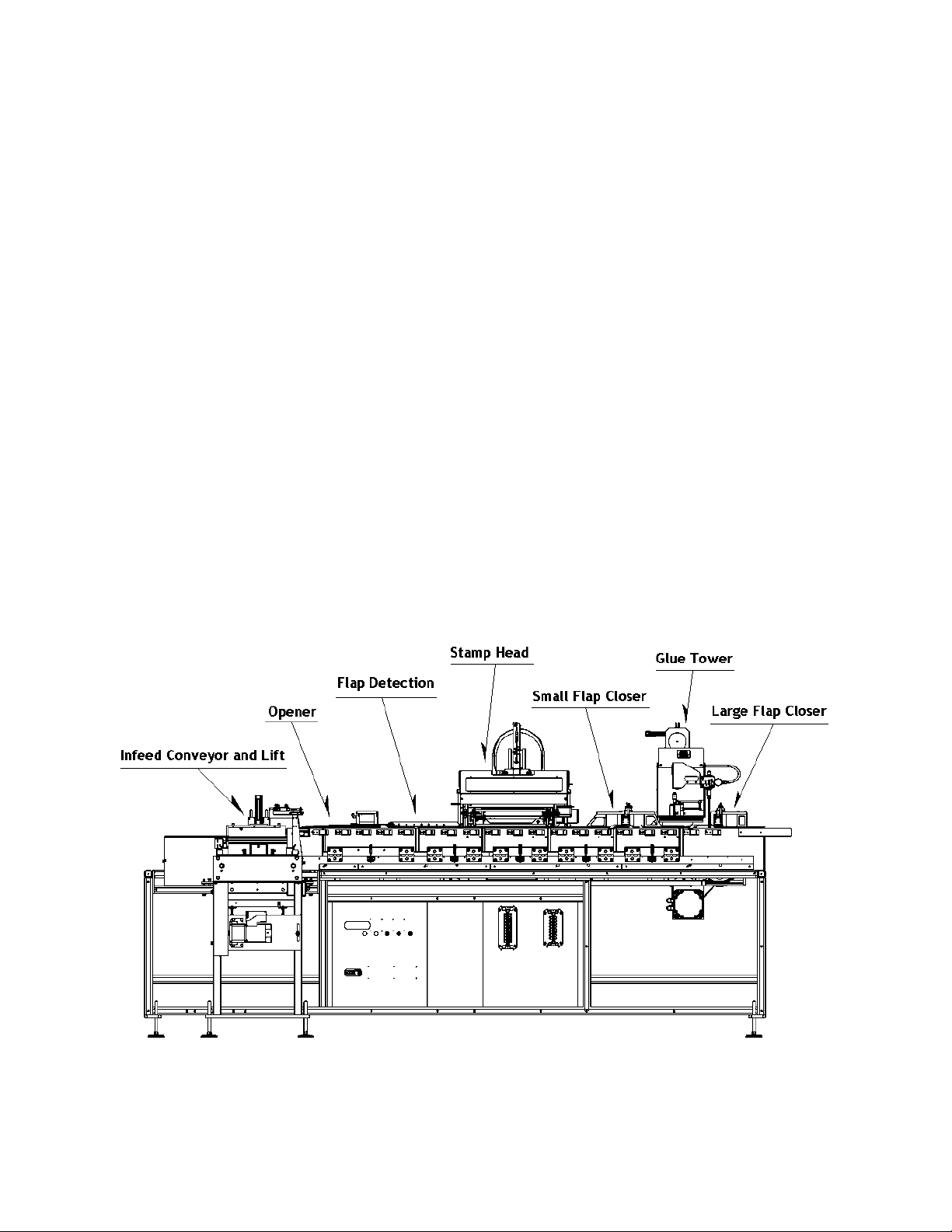
Each carton passing thru the VL-HP machine follows these steps (refer to figure 1):
The carton is placed upright on the in-feed conveyor belt, oriented with the opening flaps on
top of the carton. The VL-HP is set up to detect and open cartons regardless of orientation of
the large (outer) and small (inner) flaps. It should be noted that switching the configuration
of the closing elements adds a small amount of time to the overall cycle. Switching a few
times per case will not cause a great impact, but switching many times will cause that small
amount to add up and production time could be impacted.
The carton rides the conveyor belt until it reaches the carton trough station #1.
Figure 1 VL-HP Stations

Page 7 of 68
VL-HP Service
& Operation Manual
U.S. TAX STAMPING
EQUIPMENT
Manufactured by United Silicone
an ITW company
Once the presence of a carton is detected in the trough, the carton lifter at the in-feed
assembly lifts the carton to the ceiling plate. As the carton is processed, it is held against the
ceiling plate by a series of carton support springs.
The pusher blocks advance (index) the carton downstream to station #2 where the leading
edge of the carton is lightly squeezed by a set of wheels, causing the flaps to “dome up”
allowing the opener plow to insert under the flaps. Note: cartons pause at the end of each
index.
During the next index, the pusher block advances the carton along the length of the opener
plow causing the flaps to open. Once the index is complete, the carton flaps are detected at
station #3. The flaps are detected by a set of sensors that determine that both flaps have
opened and check whether the large flap is oriented to the front (near side) or to the back (far
side) of the trough.
The next index, the pusher block advances the carton to station #4, an idle station prior to
stamping.
During the next index, the carton is advanced onto the carton support assembly at station #5,
pushing down a floating “ramp”. When the index is complete the carton support assembly is
locked into position and the stamp head cycles, applying stamps to the individual packs.
The next index, the pusher block advances the carton again onto support springs at station #6.
A mechanism at this station positions a closer horn adjacent to the small flap side (front or
back), as determined by the sensors at station #3. There is space available between station #5
(stamping) and station #6 (small flap closer) to locate an optional cancelation device.
The next index, the pusher block advances the carton along the small flap closer horn,
closing the small flap. Once index is complete, the carton pauses at idle station #7.
During the index from station #7 to station #8, the pusher block advances the carton under a
pair of glue nozzles. The appropriate nozzle (as determined by the sensors at station #3) will
apply a small amount of glue to the closed small flap.
At station #8, a mechanism similar to the one at station #6 will position a closer horn
adjacent to the large flap side (front or back) as determined at station #3.
During the next index, the exit pusher block advances the carton along the large flap closer,
pressing the large flap onto the recently glued small flap, sealing the carton. Once closed, the
carton is ejected out of the trough and onto a packing device.

Page 8 of 68
VL-HP Service
& Operation Manual
U.S. TAX STAMPING
EQUIPMENT
Manufactured by United Silicone
an ITW company
2.1 Carton Trough Assembly
The carton trough is formed by the rear surface plates, a series of front door plates, the carton
float springs, the carton drive assembly, and the ceiling top plates.
2.1.1 Rear surface plates
The rear surface plate holds a series of flat springs that keep the cartons centered in the trough.
At each transfer station along the trough there is a sensor mounted to the rear surface plate to
detect the presence of a carton.
Fig 2.1.1 Rear surface plates (typical)
2.1.2 Front door plates
The front door plates are equipped with flat springs that keep the cartons centered. The doors are
located along the trough at each of the stations and fold down to provide access to the cartons if
needed. Each door is held closed by a toggle clamp.
Fig. 2.1.2 Front door plates (typical)
Carton Centering
Springs
Carton at Station
Sensor
Carton Centering
Springs
Door Toggle
Clamp

Page 9 of 68
VL-HP Service
& Operation Manual
U.S. TAX STAMPING
EQUIPMENT
Manufactured by United Silicone
an ITW company
2.1.3 Carton float springs
The cartons transfer through the machine on a series of angled flat springs. The springs “float”
the cartons against the various ceiling top plates. The only exception to this is at the stamping
station where the carton is held in position by the carton support assembly which locks in place
to support the carton for the stamping operation.
Fig. 2.1.3 Carton float springs (typical)
2.1.4 Carton drive assembly
The carton pusher blocks are connected to a continuous loop chain. Starting at the carton lift
station, the pusher blocks move the cartons through the trough until they exit on far end of the
machine. Each pusher block moves one carton in the downstream direction from one station to
the next during each index of the main drive.
Fig. 2.1.4 Carton drive assembly
Carton Pusher
Blocks
Drive Chain
Track
Page 10 of 68
VL-HP Service
& Operation Manual
U.S. TAX STAMPING
EQUIPMENT
Manufactured by United Silicone
an ITW company
2.1.5 Ceiling top devices
The ceiling top devices perform a variety of operations along the length of the carton trough
assembly.
2.1.5.1 Lift station top plate
The lift station top plate establishes the “working height” for all the other top devices. The in-
feed carton lift assembly lifts the cartons against this plate at station #1.
Figure 2.1.5.1 In-Feed Top Plate
2.1.5.2 Opener horn
The cartons are supported at station #2 by the opener horn.
Figure 2.1.5.2 Opener Horn

Page 11 of 68
VL-HP Service
& Operation Manual
U.S. TAX STAMPING
EQUIPMENT
Manufactured by United Silicone
an ITW company
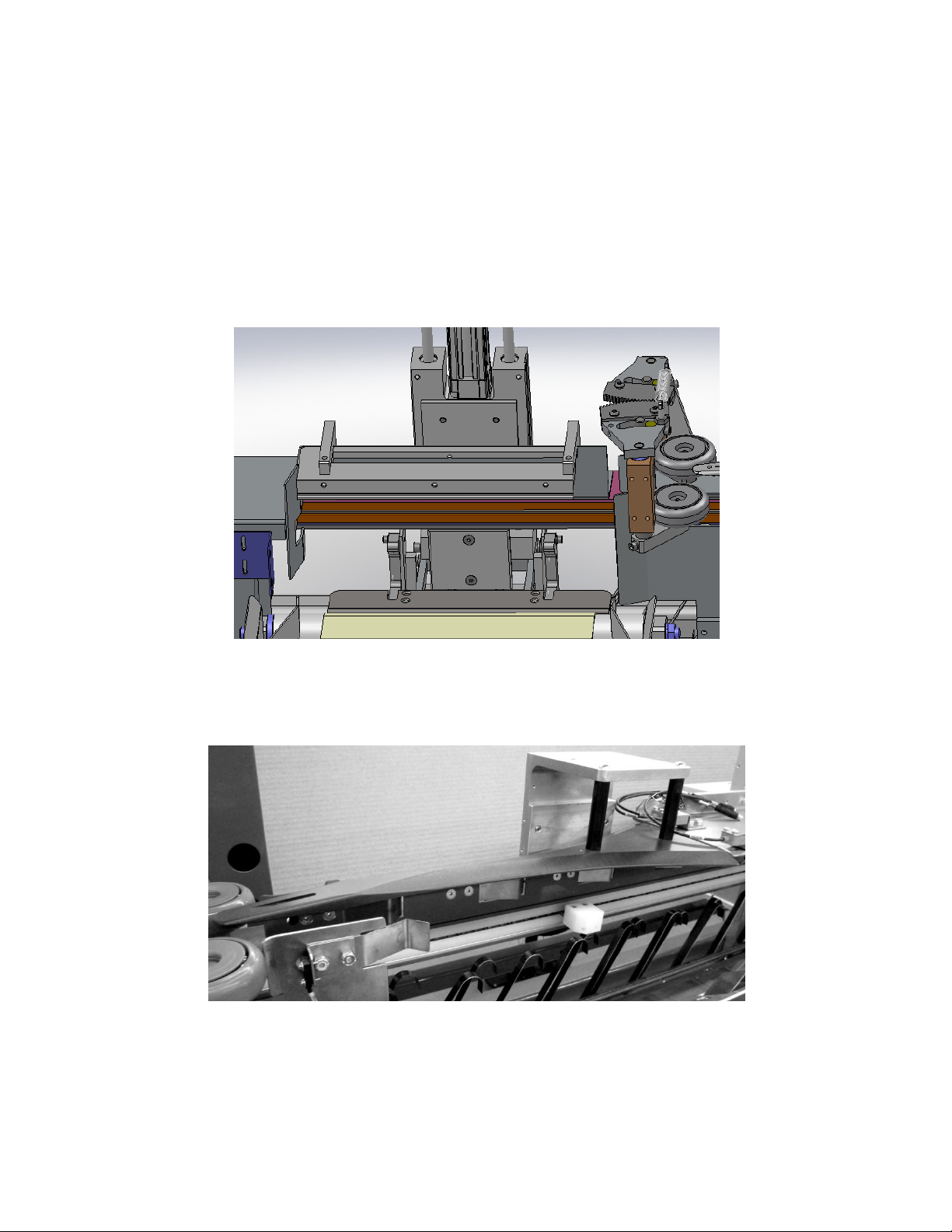
2.1.5.3 Flap detection
The cartons at station #3 and station #4 are supported by a single plate that mounts the flap
sensors. These sensors detect that both flaps have opened and on which side the large flap is
located.
Figure 2.1.5.3 Flap Sensor top plate
2.1.5.4 Stamper top plate
At the stamping station (station #5), the carton is held against the stamper top plate. This plate is
cut out to allow access for the stamp head while still supporting the cartons and retaining the
individual packs.
Figure 2.1.5.4 Stamper top plate
Page 12 of 68
VL-HP Service
& Operation Manual
U.S. TAX STAMPING
EQUIPMENT
Manufactured by United Silicone
an ITW company
2.1.5.5 Small flap closer mechanism
Because the VL-HP can open and close cartons regardless of flap orientation, it is necessary at
the small flap closer for the carton to be supported down the centerline of the two rows of packs.
This is accomplished by two support bars attached to the small flap closer mechanism. The first
bar provides carton support at station #6 during the small flap closing function. The second bar
provides carton support at station #7 and is cut for the application of glue as the carton passes
under the glue nozzles.
Figure 2.1.5.5 Small flap closer mechanism
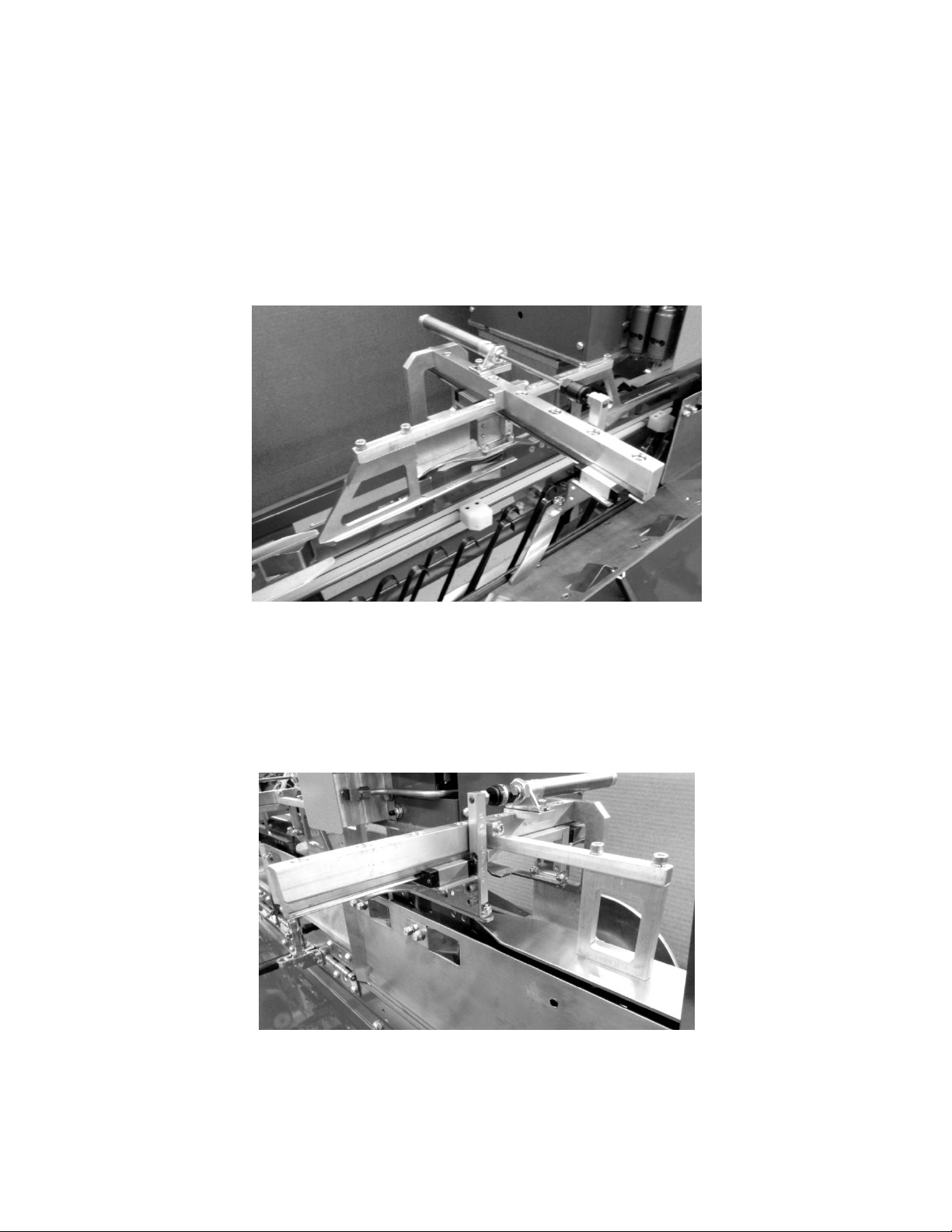
2.1.5.6 Large flap closer mechanism
At station #8, the cartons are supported by a top plate, again down the centerline of the two rows
of packs. This plate is mounted to the large flap closer mechanism and is cut out to allow the
large flap to close, regardless of which side. It also applies pressure to the carton flaps while the
hot glue sets.
Figure 2 1.5.6 Large flap closer mechanism

Page 13 of 68
VL-HP Service
& Operation Manual
U.S. TAX STAMPING
EQUIPMENT
Manufactured by United Silicone
an ITW company
3.0 Powering Up
There are 5 simple steps to turning on the VL-HP stamp machine:
Step 1: Check the glue tank, verifying sufficient hot melt glue is available
(see section 6.0 for information on the glue system)
Step 2: Turn on the electricity and compressed air.
(On electrical panel & pneumatic panel)
Step 3: Check for moisture in filter bowls-New bowls will auto drain
Step 4: Load the cartridge with the tax stamps into the stamp machine.
(refer to section 4 for information on loading stamps)
Step 5: Ensure all guards are closed and reset Emergency Stop
Turning on Electricity and Compressed Air
To start the VL-HP machine, it is necessary to turn on both electrical power and the compressed
air supply at the machine.
3.1 Electrical
Electrical power is turned on by turning the large knob on the electrical panel. This switch is
located on the door of the main electrical enclosure. The enclosure is on the back side of the
stamp machine. Turn the switch to the twelve o’clock position to turn it “ON”. To turn off the
power rotate the switch to the nine o’clock position.This switch is “Lock-Out, Tag-Out”
compliant and a lock can be applied with the switch in the “Off” position.
Figure 3.1 Electrical Lock-Out switch
After main power is turned on, the operator display panel will display a series of screens
followed by the main display screen.

Page 14 of 68
VL-HP Service
& Operation Manual
U.S. TAX STAMPING
EQUIPMENT
Manufactured by United Silicone
an ITW company
3.2 Air
An air control valve is located on the pneumatic panel located on the back of the stamp machine,
near the electrical panel. For the stamp machine to operate, the air lockout must be pushed
upwards to the correct position. This valve is “Lock-Out, Tag-Out” compliant and a lock can be
applied with the valve in the “Off” position.
Figure 3.2 Air inlet panel
Prior to turning on the supply of compressed air to the stamping machine, it is important to check
for the presence of water in the water separator bowl (1), the filter bowl (2), and the coalescing
bowl (3). The VL-HP requires that the compressed air supplied to this stamping machine be
clean and dry. All air coming from an air compressor is “wet” as a result of being compressed
by the compressor. After the air compressor, the compressed air must be dried by passing
through an aftercooler and/or air dryer. Types and advantages of different compressed air dryers
and other important information about air compressors are contained in Appendix A of this
manual “Supplying Compressed Air to your US Tax Stamping Equipment”.

Page 15 of 68
VL-HP Service
& Operation Manual
U.S. TAX STAMPING
EQUIPMENT
Manufactured by United Silicone
an ITW company
3.2.1 Moisture
If the air to the stamping machine is clean and dry, then there should be little or no
moisture in the separator bowl and filter bowl. The filters used are “auto-drain”which release
moisture as the air passes through the filter. The moisture will drain out of the bottom of the
filter shown in figure 8. A drainage line from filters to a drain is recommended.
The separator and filter bowls are more likely to fill with water. Check daily for moisture or
blockage.The air compressor and air dryer should be checked to determine why moisture is
present.If there is no moisture in the separator bowl then the compressed air can be turned
“ON” as shown.
Figure 8.

Page 16 of 68
VL-HP Service
& Operation Manual
U.S. TAX STAMPING
EQUIPMENT
Manufactured by United Silicone
an ITW company
4.0 Tax Stamps
The loading of stamps with the VL-HP has been greatly simplified. The use of a cartridge
allows quick and easy changing of the stamps.
Figure 4.0.1 End view of stamp cartridge with a new roll.
1. Insert an empty roll core on the take-up roll holders as shown in Figure 4.0.1.
2. Insure the stamps are favored towards the hole with the black square.
3. Insert the new roll of stamps on the supply roll holders as shown.
4. Ensure both rolls are FULLY seated on the holders. There should be no gaps between
the two roll cores and the roll support end plates.
5. The new roll (supply side) should come off the bottom of the roll as shown and
immediately go over the large rear roller with the wax stamps visible. The black marks
on the stamp paper will be on the side of the cartridge with the two gears, as shown in
Figure 4.0.2.
6. The paper should then pass to the bottom of the cartridge where it passes over TWO
brass rollers, as shown in Figure 4.0.3.
7. Tape the paper to the take up roll. It is very important to ensure this is done securely.
Use three pieces of tape on the core as shown in Figure 4.0.4, otherwise you will likely
encounter roll tension issues as the stamp paper indexes during production.

Page 17 of 68
VL-HP Service
& Operation Manual
U.S. TAX STAMPING
EQUIPMENT
Manufactured by United Silicone
an ITW company
Figure 4.0.2 Stamp cartridge shown with new stamp roll
(top view)
Figure 4.0.3 Stamp cartridge shown with new stamp roll
(bottom view)
Figure 4.0.4 Tape stamp paper to take up core securely in THREE places.

Page 18 of 68
VL-HP Service
& Operation Manual
U.S. TAX STAMPING
EQUIPMENT
Manufactured by United Silicone
an ITW company
4.1 Cartridge Exchanging
Before beginning these sequence of steps make sure the E-Stop is not pulled out, the main power
switch is on and product is not being run.
1) Touch the Main screen in the (lower right) for the appropriate head number is
displayed. The machine will display the Stamp Setup Screen for the selected head.
2) Write down the stamps remaining in the roll number then press the emergency stop
button on the control panel.
3) To remove the cartridge assembly open the (2) green-handled levers to unlock.
Record the stamps remaining in roll # written down in step two on the used section of
stamp carrier. This number should be verified using the numbers listed on the
stamps.
4) Write down the number of stamps remaining on the replacement roll and insert the
cartridge into stamp head. Close the two toggle clamp levers to lock the cartridge in
place.

Page 19 of 68
VL-HP Service
& Operation Manual
U.S. TAX STAMPING
EQUIPMENT
Manufactured by United Silicone
an ITW company
5) The number of stamps should now be entered on the touch screen by touching the text
box on the screen for Stamps Remaining and use the number pad to enter the stamps.
The number should be rounded down to the nearest 10. If a roll has a remaining
count of 301 the machine will not properly apply stamps to the first or last carton.
When the operator rounds down to the nearest 10 the count entered will be 300 and
the machine will end the roll on the last stamp. The old stamp should be skipped at
the start of the roll and saved for hand stamping.
6) Pull the Emergency stop knob out two position to activate paper tension and jog
modes
7) Jog carrier to position the next available stamp under stamp iron and input the display
the stamp present / no stamp present by touching “left stamp” “middle stamp” “right
stamp”
8) Touch “Jog away” so the back row of desired stamps is behind the brass roller and the
front roll of stamps is visible in front of the brass roller. Touch “index” (upper right)
to locate stamps under stamp iron.
9) Press the “main” button to return to the “main screen”.
10)Press reset button and screen should display “machine ready to run”.

Page 20 of 68
VL-HP Service
& Operation Manual
U.S. TAX STAMPING
EQUIPMENT
Manufactured by United Silicone
an ITW company
5.0 Run Mode
Once the stamps are loaded, the VL-HP is ready to run.
5.1 Machine Emergency Stop (E-Stop)
Begin by resetting E-Stop. With all guards closed, pull out on the large red Emergency Stop
button on the operator’s panel. This is a three position switch.
5.1.1 With the button pushed all the way in, the VL-HP will be put in to an “Emergency
Stop”mode, with most of the air and electrical functions disabled. This position is
maintained until the button is moved to the middle position.
5.1.2 When the button is in the middle position the VL-HP will be in normal “Run”
mode. This position also will be maintained until the button is either pushed in to cause a
stop, or pulled out to the third position.
5.1.3 The third position for this button is pulled all the way out. This is the “Reset”
position and will reset the e-stop circuit and put the VL-HP into “Ready” mode. This
position is momentary and will spring back in to the middle position once e-stop has been
reset and the button released.
There is a second E-Stop button located on the end of the machine near the carton out-feed. This
button functions in the same manner as the button on the operator’s panel. Pressing EITHER
button will cause and Emergency Stop. Keep in mind that BOTH buttons must be in the normal
“Run” position for the E-Stop circuit to reset.
5.2 Machine Homing
Once e-stop is reset, the machine will perform a brief homing cycle, moving the pusher blocks
into position to receive product.
5.3 Starting Auto Cycle
Start the machine cycle by touching and holding the “Start”button on the main touch screen for
a minimum of three seconds. The in-feed conveyor will turn on and the machine will be waiting
to accept product for stamping.
When the “Start” button is touched the display should be monitored for messages. If the
machine is not ready to start there will be a message displayed.
Table of contents
Popular Packaging Equipment manuals by other brands

Champion
Champion WHEELYBIRD 40909 instruction manual

Z.R. Tools
Z.R. Tools MS25-1 Operation manual

Fiskars
Fiskars Gifting Board instruction manual

Transpak
Transpak TP-201 Operation manual & spare parts list

Polychem
Polychem B300 Operation manual

Oliver
Oliver 1808-CE User's operating and instruction manual


