manuals.online logo
Brands
  1. Home
  2. •
  3. Brands
  4. •
  5. LEGRAND
  6. •
  7. Enclosure
  8. •
  9. LEGRAND Wiremold WAPENCL User manual

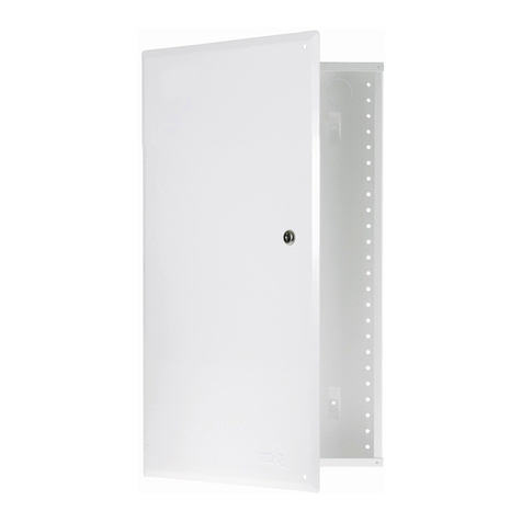
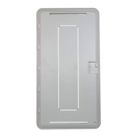
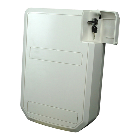
LEGRAND Wiremold WAPENCL User manual

Wiremold / Legrand Electrical Systems conform to and should be
installed and properly grounded in compliance with
requirements of the current National Electrical Code, Canadian
Electrical Code or codes administered by local authorities.
All electrical products may represent possible shock or fire
hazard if improperly installed or used. Wiremold / Legrand
electrical products are UL Listed to U.S. and Canadian safety
standards, made for interior use only, and should be installed
in conformance with current local and/or the National
Electrical Code.
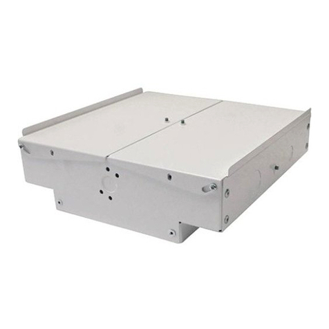
To Install WAPENCL Wireless Access Point Ceiling Enclosure:
WAPENCL, WAPENCL-24-24-4
WIRELESS ACCESS POINT CEILING ENCLOSURES
INSTALLATION INSTRUCTIONS
Installation Instruction No.: INS-WMC-017R1 – Updated December 2005
12 3/4"
[324mm]
12 1/8"
[308mm]
1. 2.
3.
4.
Locate tile and remove from ceiling grid. Remove
cover from WAPENCL Wireless Access Point Ceiling
Enclosure. Cut 12 1/8" x 12 3/4" [308mm x 324mm]
opening centered on ceiling tile.
Install fire stop foam (included) into box. Install box into
tile by pushing box through tile opening (see Step 1) and
securing the box to the tile by assembling the four Tile
Lock Brackets.
Loosely secure Grid Lock Bars to box.
Slide Grid Lock Bars to the
inward position.
NOTES: Ensure that the Wireless Access Point Box is hung from the building structure according to local codes and regulations.
The maximum weight of the Wireless Access Point unit shall not exceed 20 lbs.
WAPENCL and WAPENCL-24-24-4 comply with Article 800 of the NEC and the applicable sections of the Canadian Electrical Code.
Tile Lock
Brackets
Fire Stop
Foam
Grid Lock
Bars
IMPORTANT: Please read all instructions
before beginning.
Products Covered: WAPENCL, WAPENCL-24-24-4
7. 8.
WIREMOLD
WIREMOLD
5. 6. Determine orientation of antenna exit location and remove
desired knockout from cover. Install rubber grommet around
knockout opening.
Secure Wireless Access Point to cover using provided
hook and loop straps routed through the desired attach-
ment holes.
Attach wires to Wireless Access Point. Attach safety
chain from cover to Wireless Access Point Box. Close
and lock cover.
Remove two adjacent tiles from ceiling. Install ceiling
tile that contains Wireless Access Point Box into ceiling
grid. Adjust Grid Lock Bars to attach to ceiling grid
and tighten screws to secure in place. Install wire into
Wireless Access Point Box by routing cables through
the fire stop foam. Reinstall all ceiling tiles.
NOTE: Evenly space wires in fire stop
foam. Do not bundle wires.
Knockouts
Hook and
Loop Straps
Grommet
Eyelet for
Suspension Cable
Cover Safety
Chain
To Install WAPENCL-24-24-4 Wireless Access Point Ceiling Enclosure:
1. 2.
Remove 24" x 24" [609mm x 609mm] ceiling tile at
desired location, or remove 24" x 48" [609mm x 1219mm]
tile and cut to 24" x 24" [1219mm x 1219mm]. Insert
Enclosure into grid opening, place Enclosure Flanges
on T-Bar grid.
Adjust the four T-Bar Brackets to fit over the ceiling T-Bars,
tighten screws of each Bracket in place. Insert additional (if
required) T-Bar Support on cut tile side of Enclosure.
Secure Enclosure from four wire tie locations to building
ceiling structure (wire not included).
T-Bar
Brackets
T-Bar
Support
Wire Tie Off
(one located one
each corner of
the Enclosure)
View from above View from above
3. Remove fire stop material. Feed cables into Enclosure
through Fire Stop Bracket. Replace fire stop material once
Cables are fed (provide enough Cable for adjustments).
View from floor
4. Install Wireless Access Point onto the adjustable base using
velcro straps provided. Connect all Cables to Wireless
Access Point and adjust unit to desired depth. Tighten wing
nuts to secure unit in place.
View from floor
5. Remove required Antenna knockouts. Check
Antenna position with openings in door.
Reposition Wireless Access Point if needed
with openings. Install grommets into
openings. Re-install ceiling tiles. Remove
key, close door, and lock unit
(key is taped to inside of unit).
View from floor
Wiremold / Legrand
U.S. and International:
60 Woodlawn Street • West Hartford, CT 06110
1-800-621-0049 • FAX 860-232-2062 • Outside U.S. 860-233-6251
Canada:
570 Applewood Crescent • Vaughan, Ontario L4K 4B4
1-800-723-5175 • FAX 905-738-9721
INS-WMC-017R1 – Updated December 2005 – For latest specs visit www.wiremold.com
© Copyright 2005 Wiremold / legrand All Rights Reserved

This manual suits for next models

1

Other LEGRAND Enclosure manuals

LEGRAND Wattstopper LCAP Series User manual

LEGRAND

LEGRAND Wattstopper LCAP Series User manual

LEGRAND HX3 IS User manual

LEGRAND

LEGRAND HX3 IS User manual

LEGRAND WHAD HE 3 kVA User manual

LEGRAND

LEGRAND WHAD HE 3 kVA User manual

LEGRAND Megaline User manual

LEGRAND

LEGRAND Megaline User manual

LEGRAND NME1250AP User manual

LEGRAND

LEGRAND NME1250AP User manual

LEGRAND 6 462 40 User manual

LEGRAND

LEGRAND 6 462 40 User manual

LEGRAND 0 880 62 User manual

LEGRAND

LEGRAND 0 880 62 User manual

LEGRAND KEOR COMPACT User manual

LEGRAND

LEGRAND KEOR COMPACT User manual

LEGRAND LCS2 User manual

LEGRAND

LEGRAND LCS2 User manual

LEGRAND On-Q ENP3050 User manual

LEGRAND

LEGRAND On-Q ENP3050 User manual

LEGRAND On-Q ENP3050 User manual

LEGRAND

LEGRAND On-Q ENP3050 User manual

LEGRAND Chief PAC735 User manual

LEGRAND

LEGRAND Chief PAC735 User manual

LEGRAND Ekinoxe User manual

LEGRAND

LEGRAND Ekinoxe User manual

LEGRAND Wiremold 5500 Series User manual

LEGRAND

LEGRAND Wiremold 5500 Series User manual

LEGRAND EN1400 User manual

LEGRAND

LEGRAND EN1400 User manual

LEGRAND CHIEF CMA472 User manual

LEGRAND

LEGRAND CHIEF CMA472 User manual

LEGRAND CHIEF PAC527L Series User manual
LEGRAND

LEGRAND CHIEF PAC527L Series User manual

LEGRAND ON-Q ENP2050-NA User manual

LEGRAND

LEGRAND ON-Q ENP2050-NA User manual

LEGRAND 0 880 00 User manual

LEGRAND

LEGRAND 0 880 00 User manual
LEGRAND Trimod User manual

LEGRAND

LEGRAND Trimod User manual

LEGRAND Whad HE 3 107 74 User manual

LEGRAND

LEGRAND Whad HE 3 107 74 User manual
Popular Enclosure manuals by other brands

Teledyne Lecroy WaveRunner 9000 Assembly instructions

Teledyne Lecroy

Teledyne Lecroy WaveRunner 9000 Assembly instructions

Cooler Master CM 690 III user manual

Cooler Master

Cooler Master CM 690 III user manual

Lava FireDrive Specification sheet

Lava

Lava FireDrive Specification sheet

FRIEDHELM LOH Rittal AX 1485.744 Assembly instructions

FRIEDHELM LOH

FRIEDHELM LOH Rittal AX 1485.744 Assembly instructions

Cooper Crouse-Hinds CEAF GHG 6 Series operating instructions

Cooper Crouse-Hinds

Cooper Crouse-Hinds CEAF GHG 6 Series operating instructions

StarTech.com RK920WALM installation guide

StarTech.com

StarTech.com RK920WALM installation guide

KONG Electronic CMP-MOBSTOR13 manual

KONG Electronic

KONG Electronic CMP-MOBSTOR13 manual

Ross SideBox Installation and setup

Ross

Ross SideBox Installation and setup

Compaq StorageWorks 4100 - RAID Array user guide

Compaq

Compaq StorageWorks 4100 - RAID Array user guide

VIPowER VPM-6228H user manual

VIPowER

VIPowER VPM-6228H user manual

Fantec DB-R35DUE user manual

Fantec

Fantec DB-R35DUE user manual

Eaton MTL CROUSE-HINDS Series instruction manual

Eaton

Eaton MTL CROUSE-HINDS Series instruction manual

UFO IP-03 Product user guide

UFO

UFO IP-03 Product user guide

Johnson Controls BOX-7355-1 Product/Technical Bulletin

Johnson Controls

Johnson Controls BOX-7355-1 Product/Technical Bulletin

Crate GT412SL owner's guide

Crate

Crate GT412SL owner's guide

HP D2000 Specifications

HP

HP D2000 Specifications

CHIEF PAC502 installation instructions

CHIEF

CHIEF PAC502 installation instructions

3M 2178 instructions

3M

3M 2178 instructions

manuals.online logo
manuals.online logoBrands
  • About & Mission
  • Contact us
  • Privacy Policy
  • Terms and Conditions

Copyright 2025 Manuals.Online. All Rights Reserved.