LEGRAND Server Technology PRO1 User manual


Sentry Switched DC PDU
2 of 211

Sentry Switched DC PDU
3 of 211
About Your User Guide
This PRO1 Sentry Switched DC PDU user guide was designed for data center staff and administrators who
monitor power, control outlet actions, and direct equipment operations in the data center network using
Server Technology’s DC PDU product group.
Your user guide is a detailed resource for the PDU and its firmware user interfaces, providing:
•Interface pages, descriptions, usage, step-by-step instructions, and screen examples to assist you
with using the firmware’s Web Interface (GUI).
•Interface commands, description, syntax, usage, parameters, variables, as well as providing
command examples and results to assist you with using the firmware’s Command Line Interface
(CLI).
More Resources
Visit www.servertech.com for a wide variety of information about the PRO1 Sentry Switched DC PDU
product you have. Product support information from our power strategy experts, brochures, detailed
specifications, and many more resources –such as the innovate Build Your Own PDU and Product Selector
–are available on the Server Technology website to assist you with product knowledge, best product usage,
and an easy ordering process.
•2

Sentry Switched DC PDU
4 of 211
Contact Technical Support
Experience Server Technology's FREE Technical Support
Server Technology understands that there are often questions when installing and/or using a new product.
Free Technical Support is provided from 8 a.m. to 5 p.m. Pacific Time, Monday through Friday.
Server Technology, Inc. (a brand of Legrand)
1040 Sandhill Road Tel: 1-800-835-1515 Web: www.servertech.com

Sentry Switched DC PDU
5 of 211
Chapter 1: Introducing the PRO1 Sentry Switched DC PDU
Server Technology’s PRO1 Sentry Switched DC PDU provides
industry-standard control of cabinet equipment at remote
locations, including colocation facilities and network
operations centers.
The PRO1 Sentry Switched DC PDU gives the ability to reboot
locked-up remote servers around the clock. Features include
individual outlet current outputs, measurements, and
automated alerts for a number of low and high current needs
for the specific environmental conditions.
Fused or Breaker Power Output Protection is a feature of the
PDU, meaning each low and high current output is individually protected by its own over-current protection
device, available in a variety of current capacities. Low current GMT fuses have a visual indicator that show
when the fuses are blown.
Because the fuses are rated as disconnect switches, they can be hot-swapped without removing power to
input-feeds. In addition, optional temperature and humidity probes with 10-ft. cords allow for multiple
sensors in different locations for complete environmental monitoring
DC Products vs. AC Products
The following items list how Server Technology’s DC PDUs differ from the AC PDUs:
•DC firmware is specific to the -48V DC product line.
•All units are Switched and have a minimum of two inputs.
•Input and output connections are terminal type, not common inlets/outlets.
•Each output terminal is individually protected by a fuse or circuit breaker rated for hot disconnect.
•Relays are normally-closed instead of normally open; there is no power-up sequencing.
•True input and output “On-Sense”.
•Measures only current (amps) at each output (no input/aggregate measurements, no voltage
measurement).
•Direct current (DC) is simpler than alternating current (AC); only need to know Watt’s Law:
Watts = Volts x Amps
Volts = Watts / Amps
Amps = Watts / Volts


Sentry Switched DC PDU
6 of 211
Advantages of the PRO1 Sentry Switched DC PDU
The PRO1-based DC product line is based on Server Technology’s PRO1 PDU platform and firmware, which
offers:
•Faster processor and more memory
•Hot swap network card
•Network card swap with no re-programming (PCM)
•Features/functions can be added as needed
•Multi-linking (up to 4 linked units, 1 master unit and 3 link units)
•Power from link unit keeps network up if power from master unit goes down
•Sentry4-MIB allows additional alarm warning and threshold levels

Sentry Switched DC PDU
7 of 211
Key Features
Several notable features of Server Technology’s PRO1 Sentry Switched DC PDUs include:
Output Control
Cycle power to individual outputs or groups of outputs to reboot servers or to
power off unused terminals.
Output Current
Monitoring
Network monitoring provides access to current draw at each output and alerts
when high usage risks a tripped circuit.
Disconnect Rated
Circuit Protection
Each output is protected by a fuse or circuit breaker and is rated for hot
disconnect.
Temperature/Humidity
Monitoring
Master and Link units (select products) each support two external 10-ft (3m) T/H
probes. Receive SNMP-based alerts and email notifications.
Network Monitoring
Gain access to valuable data through connections, including HTTP(S), SSH, Telnet,
SNMP, (S)FTP, SMPT, Syslog, LDAP(S), RS-232 serial, and more.
Linkable Expansion
Connect an expansion rack PDU to a master rack PDU for power monitoring of
separate power circuits from a single IP address.

Sentry Switched DC PDU
8 of 211
Additional Features of DC Products:
•TCP/IP Control to configure/manage and remotely Power On, Power Off, or Reboot attached devices
via:
•Web GUI and CLI access via network
•Out-of-Band access to CLI via serial/console port
•Current (amps) is measured at each individual output
•Multiple User Simultaneous Access
•Firmware flash-upgrade available by various methods
•Logging via internal log, Email/SMTP, and Syslog
•LDAP[S]/Active Directory, RADIUS, and TACACS+ Authentication and Authorization support
•Each model supports two (2) combination temperature & relative humidity environmental sensors
Part numbers EMTH-2-10 (10 ft) and EMTH-2-20 (20 ft)
•Supports optional Environmental Monitor Control Unit (EMCU-1-1C)
•Supports StartUp Stick for configuration of initial network settings
•Unique Expansion Capability:
One master PRO1 Sentry Switched DC PDU can be linked to up to three DC link units
oAccommodates redundant setup with no single-point of failure
oMore than one link unit requires multi-link dongle (Part number KIT-PRO2LINK-01D)
oLogical grouping of any outputs in the system (master and link units)
•Nominal operating range for voltage is -40V to -60V
•IMPORTANT: Requires a negative (-) DC system
•Server Technology JSON API Web Service (JAWS)
•Server Technology INI Configuration (STC) file format
•SNMP v2c and v3; same Sentry4.mib and OID Tree as with PRO Series AC products
•Most models rated for 0°C to 50°C operation
•Network Equipment-Building System (NEBS) Certification (certain models)
NEBS Certified

Sentry Switched DC PDU
9 of 211
Chapter 2: The PRO1 Sentry Switched DC PDU Models
This chapter shows unit drawings, hardware specifications, terminal stud spacing diagrams, and fuse/circuit
breaker information.
48DCWC-16-2X100-A0
Terminal Stud Spacing
The 48DCWC-16-2X100-A0 terminal stud spacing:

Sentry Switched DC PDU
10 of 211
Mounting Bracket
The 48DCWC-16-2X100-A0 mounting bracket:

Sentry Switched DC PDU
11 of 211
48DCWC-04-2X100-D0NB
Terminal Stud Spacing
The 48DCWC-04-2X100-D0NB terminal stud spacing:

Sentry Switched DC PDU
12 of 211
Mounting Bracket
The 48DCWC-04-2X100-D0NB mounting bracket:

Sentry Switched DC PDU
13 of 211
48DCWC-12-2X100-A1NB
Terminal Stud Spacing
The 48DCWC-12-2X100-A1NB terminal stud spacing:

Sentry Switched DC PDU
14 of 211
Mounting Bracket
The 48DCWC-12-2X100-A1NB mounting bracket:

Sentry Switched DC PDU
15 of 211
48DCWC-08-2X100-B0NB
Terminal Stud Spacing
The 48DCWC-08-2X100-B0NB terminal stud spacing:

Sentry Switched DC PDU
16 of 211
Mounting Bracket
The 48DCWC-08-2X100-B0NB mounting bracket:

Sentry Switched DC PDU
17 of 211
48DCWC-04-4X070-D0NB
Terminal Stud Spacing
The 48DCWC-04-4X070-D0NB terminal stud spacing:

Sentry Switched DC PDU
18 of 211
Mounting Bracket
The 48DCWC-04-4X070-D0NB mounting bracket:

Sentry Switched DC PDU
19 of 211
48DCWC-04-4X125-E0NB
Terminal Stud Spacing
The 48DCWC-04-4X125-E0NB terminal stud spacing:

Sentry Switched DC PDU
20 of 211
Mounting Bracket
The 48DCWC-04-4X125-E0NB mounting bracket:
This manual suits for next models
16
Table of contents
Other LEGRAND Network Hardware manuals

LEGRAND
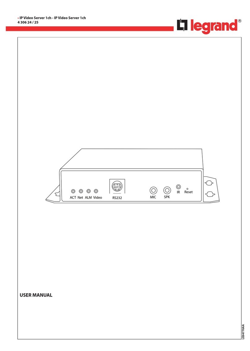
LEGRAND 4 306 24 User manual

LEGRAND
LEGRAND 0 490 87 User manual

LEGRAND
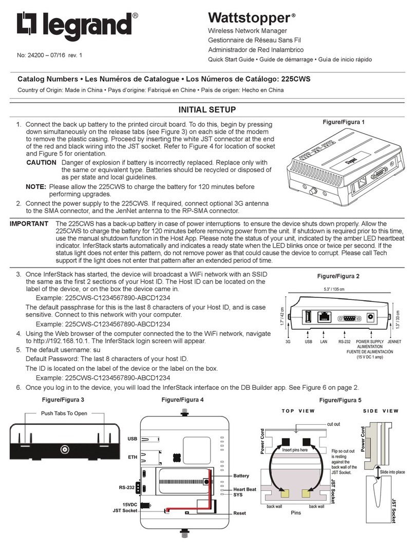
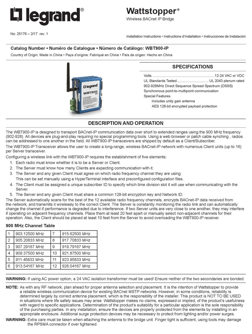
LEGRAND Wattstopper WBT900-IP User manual

LEGRAND
LEGRAND 369420 User manual

LEGRAND
LEGRAND LMBC-600 User manual

LEGRAND
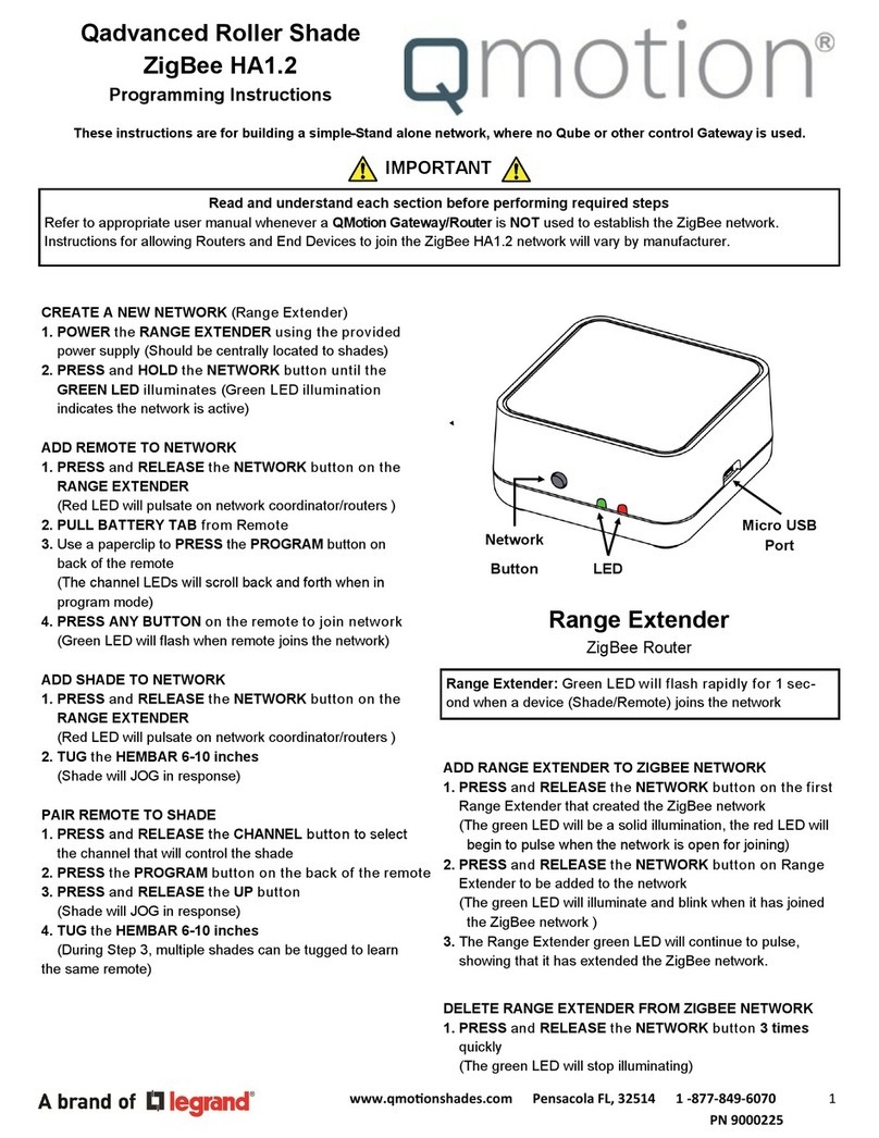
LEGRAND Qmotion Range Extender Installation manual

LEGRAND
LEGRAND HA7040 User manual

LEGRAND
LEGRAND Wattstopper 225CWS User manual

LEGRAND
LEGRAND 0 677 66 User manual

LEGRAND
LEGRAND DA2401 User manual