Leica BIOSYSTEMS CM3600 XP User manual

Instructions for Use
English
Order No.: 14 0417 80101 - Revision H
Always keep this manual with the instrument.
Read carefully before working with the instrument.
Version 6.9, Revision H - 11.2020
Leica CM3600 XP
Cryostat


3
Leica CM3600 XP
The information, numerical data, notes and value judgments contained in this Instructions for Use
represent the current state of scientic knowledge and state-of-the-art technology as we understand
it following thorough investigation in this eld.
We are under no obligation to update the present Instructions for Use periodically and on an ongoing
basis according to the latest technical developments, nor to provide our customers with additional
copies, updates etc. of this Instructions for Use.
To the extent permitted in accordance with the national legal system as applicable in each individual
case, we shall not be held liable for erroneous statements, drawings, technical illustrations etc. contained
in this Instructions for Use. In particular, no liability whatsoever is accepted for any nancial loss or
consequential damage caused by or related to compliance with statements or other information in this
Instructions for Use.
Statements, drawings, illustrations and other information regarding the contents or technical details of
the present Instructions for Use are not to be considered warranted characteristics of our products.
These are determined only by the contract provisions agreed between ourselves and our customers.
Leica reserves the right to change technical specications as well as manufacturing processes without
prior notice. Only in this way is it possible to continuously improve the technology and manufacturing
techniques used in our products.
This document is protected under copyright laws. All copyrights to this documentation are held by
LeicaBiosystems Nussloch GmbH.
Any reproduction of text and illustrations (or of any parts thereof) by means of print, photocopy,
microche, web cam or other methods – including any electronic systems and media – requires express
prior permission in writing by Leica Biosystems Nussloch GmbH.
For the instrument serial number and year of manufacture, please refer to the nameplate on the back of
the instrument.
Note
Leica Biosystems Nussloch GmbH
Heidelberger Strasse 17 - 19
69226 Nussloch
Germany
Tel.: +49 - (0) 6224 - 143 0
Fax: +49 - (0) 6224 - 143 268
Web: www.LeicaBiosystems.com

4Version 6.9, Revision H
Table of contents
1. Important Information ..................................................................................................7
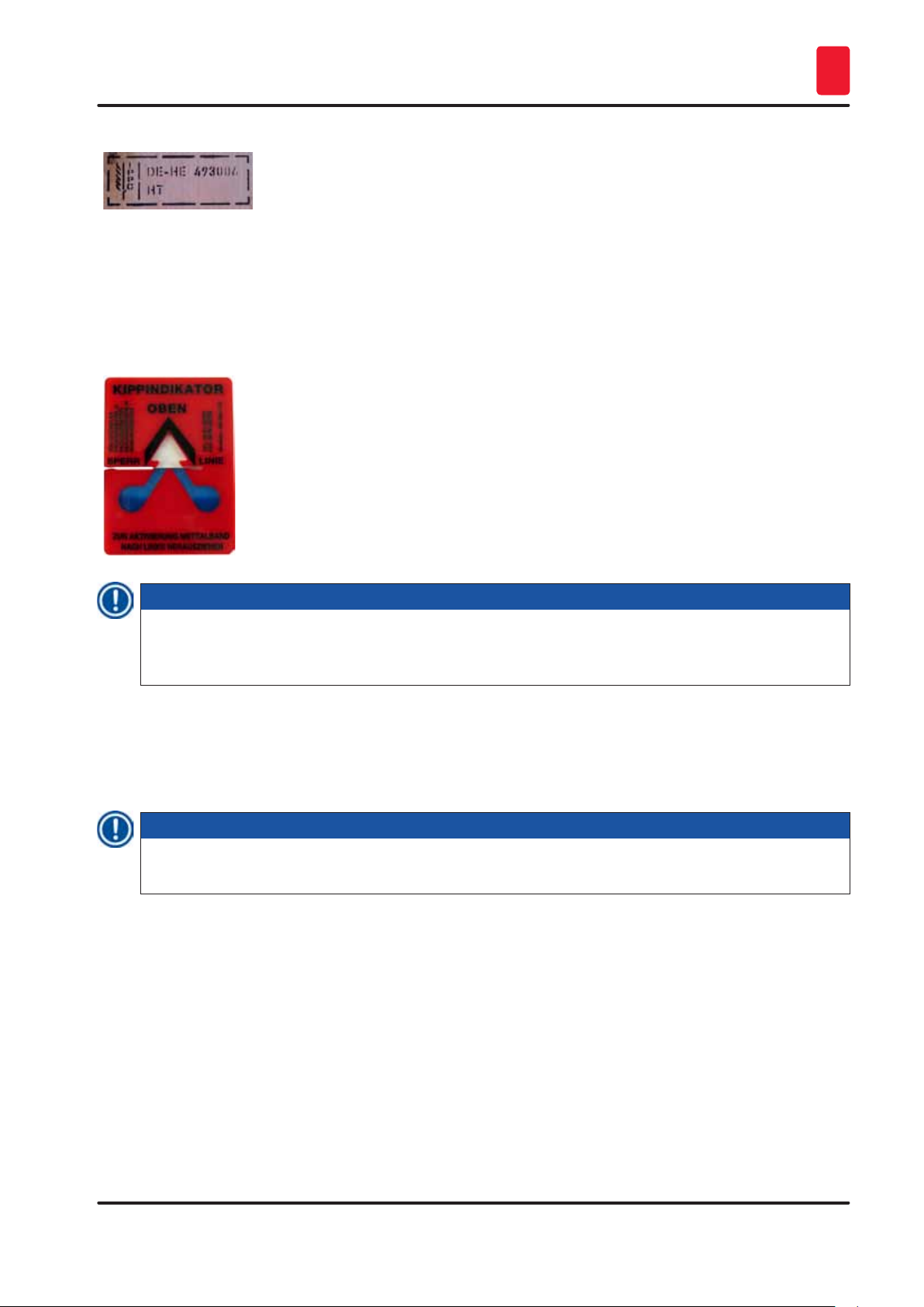
1.1 Symbols and their meaning ........................................................................................................ 7
1.2 Instrument type ......................................................................................................................... 9
1.3 User group................................................................................................................................. 9
1.4 Intended use.............................................................................................................................10
2. Characteristics of the Leica CM3600 XP........................................................................11
2.1 Layout of the Leica CM3600 XP.................................................................................................11
2.2 Technical data ..........................................................................................................................12
2.3 Instrument parts .......................................................................................................................14
2.4 Function...................................................................................................................................15
3. Safety......................................................................................................................16
3.1 Safety notes .............................................................................................................................16
3.2 Warnings..................................................................................................................................16
3.3 Safety features .........................................................................................................................18
3.3.1 Emergency stop switch .............................................................................................................18
3.3.2 Knee lever ................................................................................................................................19
3.3.3 Window ....................................................................................................................................20
3.3.4 Cabinet ....................................................................................................................................20
4. Site requirements......................................................................................................21
4.1 Site requirements at place of installation ...................................................................................21
4.2 Electrical connections...............................................................................................................22
4.3 Other connections.....................................................................................................................22
5. Installation...............................................................................................................23
5.1 Unpacking and installation ........................................................................................................23
5.2 Standard delivery ......................................................................................................................23
5.3 Port and switch panel ...............................................................................................................24
5.3.1 Port and switch functions..........................................................................................................25
5.3.2 Fuses .......................................................................................................................................26
5.4 PC............................................................................................................................................27
6. Software ..................................................................................................................28
6.1 Start and log-in procedure .........................................................................................................28
6.2 Description of the window elements ..........................................................................................29
6.3 Initialization..............................................................................................................................31
6.4 Main window ............................................................................................................................32
6.4.1 Chamber temperature ...............................................................................................................32
6.4.2 Time ........................................................................................................................................33
6.4.3 Automatic defrost.....................................................................................................................33
6.4.4 Automatic dehydration ..............................................................................................................33
6.4.5 Knife movement........................................................................................................................33
6.4.6 Extraction system .....................................................................................................................35
6.4.7 Section program .......................................................................................................................35
6.4.8 Sledge speed............................................................................................................................36
6.4.9 Operation mode ........................................................................................................................36
6.4.10Cutting window.........................................................................................................................37

5
Leica CM3600 XP
Table of contents
6.5 Parameter settings....................................................................................................................37
6.5.1 Parameter settings....................................................................................................................38
6.5.2 Password management.............................................................................................................41
6.5.3 Conguration............................................................................................................................43
6.5.4 Reference voltages ...................................................................................................................47
6.5.5 Language selection...................................................................................................................47
6.5.6 Initialization..............................................................................................................................48
6.6 Temperature curves ..................................................................................................................48
6.6.1 Work space...............................................................................................................................49
6.6.2 Diagram ...................................................................................................................................49
6.7 Chronological event list.............................................................................................................50
6.7.1 Work space...............................................................................................................................51
6.7.2 Event list ..................................................................................................................................52
6.8 Alarm list..................................................................................................................................52
6.8.1 Work space...............................................................................................................................53
6.8.2 Alarm list..................................................................................................................................54
6.8.3 Error messages: Meaning and troubleshooting...........................................................................55
6.9 Chamber illumination ................................................................................................................55
6.10 Section documentation .............................................................................................................55
6.11 Photo mode..............................................................................................................................59
6.12 Screen printout .........................................................................................................................59
6.13 Help .........................................................................................................................................59
6.14 Save.........................................................................................................................................59
6.15 Printing labels ..........................................................................................................................60
6.16 Foot switch...............................................................................................................................60
6.17 User log-in/log-out ....................................................................................................................60
6.18 Quitting the application .............................................................................................................60
7. Operating the Leica CM3600 XP...................................................................................61
7.1 Check list .................................................................................................................................61
7.2 Switching the instrument on ......................................................................................................61
7.3 Starting the software ................................................................................................................61
7.4 Setting the chamber temperature...............................................................................................62
7.5 Specimen stages ......................................................................................................................62
7.5.1 Inserting the specimen stage, orientable, with ball-joint ..............................................................63
7.6 Knife ........................................................................................................................................65
7.6.2 Inserting the disposable blade holder with disposable blade.......................................................67
7.6.3 Adjusting the knife angle...........................................................................................................69
7.9 Dehydrating the sections...........................................................................................................71
7.10.2Knife holder description ............................................................................................................73
7.10.5Sectioning thick blocks .............................................................................................................75

6Version 6.9, Revision H
Table of contents
8. Cleaning and Maintenance ..........................................................................................76
8.1 Cleaning...................................................................................................................................76
8.1.1 Removing the microtome...........................................................................................................76
10. Warranty and Service .................................................................................................82
11. Decommissioning and Disposal ...................................................................................83
12. DecontaminationConrmation ....................................................................................84

7
Leica CM3600 XP
Important Information 1
1. Important Information
1.1 Symbols and their meaning
Symbol: Title of the symbol: Warning
Description: Warnings appear in a white box, orange header and
are marked by a warning triangle.
Symbol: Title of the symbol: Note
Description: Notes,i. e.importantuserinformation,appearin
a white box, blue header and are marked by an
information symbol.
Symbol: Title of the symbol: Warning,lowtemperature/freezingconditions
Description: Instrument parts close to this symbol are exposed
tolowtemperatures/freezingconditionsthat
pose a threat to health. Avoid direct contact or use
appropriate protective clothing, e.g. frost protection
gloves.
Symbol: Title of the symbol: Item number
→"Fig. 7-1"Description: Item numbers for numbering illustrations. Numbers in
red refer to item numbers in illustrations.
Symbol: Title of the symbol: Function key
Save Description: Software symbols that have to be pressed on the
input screen are displayed as bold, gray text.
Symbol: Title of the symbol: Keys and switches on the instrument
Start Description: Keys and switches on the instrument that are
supposed to be pressed by the user in various
situations are displayed as bold, gray and underlined
text.
Symbol: Title of the symbol: Attention
Description: Indicates the need for the user to consult the
Instructions for Use for important cautionary
information such as warnings and precautions that
cannot, for a variety of reasons, be presented on the
medical device itself.
Special meaning of this symbol located at the
microtome sledge: (→p. 18 – Microtome sledge)
Symbol: Title of the symbol: Warning, risk of electric shock
Description: Instrument surfaces or areas which become energized
during operation are marked with this symbol.
Therefore, direct contact is to be avoided.
Symbol: Title of the symbol: China ROHS
Description: Environmental protection symbol of the China RoHS
directive. The number in the symbol indicates the
"Environment-friendly Use Period" of the product.
The symbol is used if a substance restricted in China
is used in excess of the maximum permitted limit.

8Version 6.9, Revision H
Important Information
1
Symbol: Title of the symbol: WEEE Symbol
Description: Symbol for labeling electrical and electronic
equipmentinaccordancewithSection7ofthe
German Electrical and Electronic Equipment Act
(ElektroG). ElektroG is the law regarding the sale,
return and environmentally sound disposal of
electrical and electronic equipment.
Symbol: Title of the symbol: CE Compliance
Description: CE labeling shows that the product corresponds to
one or more applicable European directives.
Symbol: Title of the symbol: Manufacturer
Description: Indicates the manufacturer of the medical product.
Symbol: Title of the symbol: Manufacturing date
Description: Indicates the date when the medical device was
manufactured.
Symbol: Title of the symbol: Article number
Description: Indicates the manufacturer's catalog number so that
themedicaldevicecanbeidentied.
Symbol: Title of the symbol: Serial number
Description: Indicates the manufacturer's serial number so that
aspecicmedicaldevicecanbeidentied.
Symbol: Title of the symbol: Consult Instructions for Use
Description: Indicates the need for the user to consult the
Instructions for Use.
Symbol: Title of the symbol: Fragile, handle with care
Description: The package contents are fragile and must be handled
with care.
Symbol: Title of the symbol: This way up
Description: Indicates correct upright position of the transport
package.
Symbol: Title of the symbol: Store dry
Description: The package must be kept in a dry environment.

9
Leica CM3600 XP
Important Information 1
Symbol: Title of the symbol: IPPC symbol
Description: The IPPC symbol includes
• IPPC symbol
• Country code in accordance with ISO 3166,
e. g.DEforGermany
• Regionalidentier,e. g.HEforHesse
• Registration number, unique number beginning with
49.
• Treatmentcode,e. g.HT(heattreatment),MB
(methyl bromide), and possibly DB (debarked)
Example of labeling in
accordance with IPPC
Appearance: Indication: Tilt indicator
Description: Tip-n-Tell indicator to monitor whether the shipment
has been transported and stored in upright position
according to your requirements. With a tilt of 60°
ormore,thebluequartzsandowsintothearrow-
shapeddisplayeldandremainstherepermanently.
Improper handling of the shipment is immediately
detectableandcanbeprovendenitively.
Note
When delivering the instrument, the recipient must check that the tilt indicator is intact. The
responsibleLeicarepresentativemustbenotiedinthecasethatoneorallindicatorshavebeen
triggered.
1.2 Instrument type
All information provided in these Instructions for Use applies only to the instrument type indicated on the
title page. An nameplate with the serial number is attached on the center on the rear side of the cabinet.
Note
TheexactdataofthedifferentinstrumentversionsarespeciedinChapter(→p. 12 – 2.2 Technical
data).
1.3 User group
Only trained laboratory personnel may operate the Leica CM3600 XP. The instrument is intended for
professional use only.
Prior to operating the instrument, the operator must carefully read and understand these Instructions for
Use and must familiarize him/herself with all technical details of the instrument.

10 Version 6.9, Revision H
Important Information
1
1.4 Intended use
The Leica CM3600 XP is a PLC-controlled and motorized precision cryomacrotome for largesurface
sections, equipped with a convection-cooled chamber for deep-freezing, sectioning and freeze-drying
large biological and industrial specimens.
The instrument is designed for the aforementioned applications only and must be operated according to
the instructions in these Instructions for Use.
Warning
Any use of the instrument not described in these Instructions for Use is considered improper.
If you wish to use the instrument for special applications or modes of operation not listed in this manual,
it is absolutely necessary that you contact your local Leica representation prior to doing so.
Otherwise, you will loose the Leica warranty on your instrument.
Only trained personnel, skilled in the use of the above-mentioned applications, may operate the
Leica CM3600 XP.
Prior to working with the instrument, each operator must thoroughly read and understand these
Instructions for Use.

11
Leica CM3600 XP
Characteristics of the Leica CM3600 XP 2
2. Characteristics of the Leica CM3600 XP
2.1 Layout of the Leica CM3600 XP
3
7
1
9
4
8
2
10
5 6
Fig. 1
1 PC Commercially available computer with monitor, keyboard and mouse.
2 Port and switch
panel
The port and switch panel contains the main power switch and several sockets
and ports.
3 Refrigeration and
control unit
The refrigeration and control unit cools the cryochamber and controls the
microtome and the entire electronics.
4 Emergency stop
switch
Press the Emergency stop switch to stop the microtome immediately.
5 Window The window is heated and can be opened completely.
6 Microtome
(in the cabinet)
The microtome is used to section the specimens.
7 Chamber lid The chamber lid can be opened completely for maintenance and cleaning work
on microtome and/or cryochamber.
8 Cabinet The cabinet contains the cryochamber which houses the microtome.
9 Knee lever The knee lever is used for manual operation of the specimen sledge.
10 Drain valve for
condensation
water
Condensation water is drained through the drain valve. The drain valve should
always be open to prevent the backup of condensation water. The tray at the
drain valve must remain at the instrument at all times and must be emptied
regularly.

12 Version 6.9, Revision H
Characteristics of the Leica CM3600 XP
2
2.2 Technical data
Microtome type
450 C Sliding microtome
Sectioning thickness setting: 1 - 500 μm,in1 μmincrements
Sectioning range: 0 - 450 mm
Max. sectioning speed: 80 mm/s
Knife retraction after sectioning stroke: 50 - 250μm
Total vertical stroke of knife: 100 mm
Total specimen feed: 450 mm
Specimen orientation via ball-and-socket joint: approx. 5° (x/y/z-axis)
Specimen orientation via large specimen stage
(450x150 mm):
Rotation around longitudinal axis (x-axis)
Maximum specimen size (L x W x H): 450x150x200 mm
Knife holder for steel and tungsten carbide knife: 160 mm
Knife holder for disposable blade holder: 160 mm
Knife(160 mm)withfacetangleof: 20°, 35°
Control unit
The Leica CM3600 XP is equipped with a commercially available computer with monitor, keyboard and
mouse. For further information, please refer to the manual of the PC.
Operating system: Windows®
Software: CM3600 XP version 3.2.2
Dimensions and weights
Inner (cryochamber L x H x W): 1650x720x600 mm
Outer (L x H x W): 2800x1090x920 mm
Total dimensions with connecting lines:
• Outer length (overall): 2800 mm
• Outer length (cabinet only): 1940 mm
• Outer length (control unit): 860 mm
• Outer height (overall): 1090 mm
• Outer height (working height): 1050 mm
• Outer width: 920 mm
• Weight (total weight incl. microtome) 660 kg
• Weight (microtome only): 190 kg
Electrical connections
380 V / 50 Hz
• Nominal supply voltages: 380 V AC±10 %

13
Leica CM3600 XP
Characteristics of the Leica CM3600 XP 2
• Nominal frequency: 50 Hz
• Line voltage tolerance: ±10 %
• Power draw: 2400 VA
• Automatic cutout: 3x8 A / 1x16 A
• Power safety switch inaccordancewithDINIEC127-2
• Power plug (CEE, in accordance with IEC 60309) MennekesProTOP13A(tstosockettype3473)
208 V / 60 Hz
• Nominal supply voltages: 208 V AC
• Nominal frequency: 60 Hz
• Line voltage tolerance: ±10 %
• Power draw: 2400 VA
• Automatic cutout: 2x8 A / 1x10 A
• Power safety switch UL-listed
• Power plug (CEE, in accordance with IEC 60309) MennekesME320P6W(tstosockettype
ME320R6W)
200 V / 50 Hz
• Nominal supply voltages: 200 V AC
• Nominal frequency: 50 Hz
• Line voltage tolerance: ±10 %
• Power draw: 2400 VA
• Automatic cutout: 2x8 A / 1x10 A
• Power safety switch UL-listed
• Power plug (CEE, in accordance with IEC 60309) MennekesProTOP148A(tstosockettype1632)
200 V / 60 Hz
• Nominal supply voltages: 200 V AC
• Nominal frequency: 60 Hz
• Line voltage tolerance: ±10 %
• Power draw: 2400 VA
• Automatic cutout: 2x8 A / 1x10 A
• Power safety switch UL-listed
• Power plug (CEE, in accordance with IEC 60309) MennekesProTOP148A(tstosockettype1632)
220 V / 60 Hz
• Nominal supply voltages: 220 V AC
• Nominal frequency: 60 Hz
• Line voltage tolerance: ±10 %
• Power draw: 2400 VA
• Automatic cutout: 2x8 A / 1x10 A
• Power safety switch UL-listed
• Power plug (CEE, in accordance with IEC 60309) MennekesProTOP148A(tstosockettype1632)

14 Version 6.9, Revision H
Characteristics of the Leica CM3600 XP
2
Refrigeration system – cryochamber
Selectable temperature range: 0 °Cto-30 °C
Atanambienttemperatureof22 °C,closedwindow
andhumidity≤60 %:
-30 °C±10 %(adjustablein1 Kincrements)
Control accuracy: +1to-3 K
Electrical power consumption: 1160 W
Refrigeratingoutputat-25 °C: 1370 W
Nominal pressure: 20 bar(maximumvalue)
Cutoff pressure: 25 bar(viaPressostat)
Safety factor: 2, as per UL 1262
Refrigerant: 1100 g,refrigerantR452A
Compressor oil: 1220 cm3Alpha 22, Kyodo
Defrosting: Automatic hot gas defrost, programmable, 2 x
automatic hot gas defrost/24 hours. Duration:
1 - 15minutes,manualdefrost.
General parameters
Protection class: I
Pollution degree: 2
Overvoltage category: II
Noise information
A-weighted noise level: 78.5 dB(A)
Distance between sound meter and instrument: 1 meter
Measuring uncertainty: ±1.5 dB(A)
Instrument setting for measurement: Normal instrument operation with extraction
Warning
The user must wear hearing protection when using the extraction.
2.3 Instrument parts
The Leica CM3600 XP consists of a sliding microtome in a large-volume cryochamber. The instrument is
designed for cryosectioning large specimens or for processing specimens with the so-called cryo-planing
technique.
The large-scale heavy-duty microtome of the instrument is made for sectioning large biomedical and
industrial specimens such as whole animals or large tissue specimens by applying the sectioning
techniques for large-surface sections. The sturdy construction of the instrument also permits sectioning
veryhardspecimenssuchasundecalciedbones.

15
Leica CM3600 XP
Characteristics of the Leica CM3600 XP 2
The microtome is housed in a convection-cooled large-volume cryochamber. The large chamber in
connection with the special cooling system enables dehydration of sections within a very short time.
The low temperatures are achieved and maintained by cold air circulating inside the cryochamber.
A fan controls the air circulation speed.
The large specimens are frozen onto metal specimen stages which are subsequently clamped in the
specimen sledge.
Optionally the instrument can be operated with an extraction system which largely prevents the
cryochamber being soiled with section waste.
2.4 Function
The motor-driven specimen sledge moves horizontally underneath the knife, either producing a section
(cryosectioning) with each stroke or a high-quality specimen surface (cryo-planing technique).
Prior to each sectioning stroke, a stepper motor feeds the microtome knife downwards towards the
specimen by a selected amount of microns (section thickness).
During each return stroke of the specimen sledge, the stepper motor automatically carries out a knife
retractionmovement,programmablebetween50and250 μm.Thisprotectsboththeknifebladeandthe
specimen surface from being damaged.
Before starting the next sectioning stroke, the motor lowers the knife towards the specimen surface by
the selected sectioning feed plus the set value for knife retraction.
Trimming is programmable; the desired section thickness can be preselected. The number of sections
to be performed during trimming can be programmed via the section counter. When the programmed
number of sections has been carried out, the microtome will stop automatically.
Once the desired specimen block height has been reached, those sections that will actually be used for
further examination are collected manually via the knee lever.
The Leica CM3600 XP is operated via PC and/or manually via the knee lever. All data entries are made via
the PC.
The Leica CM3600 XP features two automatic defrost cycles.
Defrost cycle duration is software-controlled. If the evaporator surface is already completely deiced
before the programmed defrost time is up, the defrost cycle will be aborted. In addition, manual defrost
cycles can be set as needed.

16 Version 6.9, Revision H
Safety
3
3. Safety
Warning
The safety and caution notes in this chapter must be observed at all times.
Be sure to read these notes even if you are already familiar with the operation and use of other
Leicaproducts.
3.1 Safety notes
These Instructions for Use include important instructions and information related to the operating safety
and maintenance of the instrument.
The Instructions for Use are an important part of the product, and must be read carefully prior to startup
and use and must always be kept near the instrument.
Note
These Instructions for Use must be appropriately supplemented as required by the existing regulations
on accident prevention and environmental safety in the operator's country.
This instrument has been built and tested in accordance with the safety requirements for electrical
equipment for measurement, control and laboratory use.
To maintain this condition and ensure safe operation, the user must observe all notes and warnings
contained in these Instructions for Use.
Note
For current information about applicable standards, please refer to the CE declaration for the
instrument and to our Internet site:
http://www.LeicaBiosystems.com
Warning
The protective devices located on the instrument and the accessories must not be removed or
modied.OnlyqualiedservicepersonnelauthorizedbyLeicamayrepairtheinstrumentandaccessits
internal components.
3.2 Warnings
The safety devices installed in this instrument by the manufacturer only constitute the basis for accident
prevention. Operating the instrument safely is, above all, the responsibility of the owner, as well as the
designated personnel who operate, service or repair the instrument.
To ensure trouble-free operation of the instrument, make sure to comply with the following instructions
and warnings.

17
Leica CM3600 XP
Safety 3
Warning
• Theprotectivedevicesontheinstrumentmustneitherberemovednormodied.
• The instrument has to be connected to an appropriate and grounded socket, (→p. 12 – 2.2
Technical data).
• Do not interfere with the grounding function by using an extension cord without a ground wire.
• Use extreme caution when handling microtome knives and disposable blades.
• Handle knives and blades as per manufacturer's directions.
• Never operate the instrument in rooms with an explosion hazard.
• During instrument setup/installation do not switch the instrument on before being prompted to do
so by these Instructions for Use.
• While working through these Instructions for Use, do not insert either the knife or the specimen
block.
• The lid of the instrument must always be opened by two persons. No one must work on the
instrument until it has been ensured that the lid has latched into place.
BelowyoundasummaryofallwarningscontainedintheseInstructionsforUse.
Warning
• Any use of the instrument not described in these Instructions for Use is considered improper.
• Always swing the knee lever upwards before leaving the instrument.
• The chamber lid must be lifted by 2 persons when opened. When opening the chamber lid, the lid
retainer must engage. Only when the lid is lifted can the user work in the instrument.
• Prior to any work involving the knife, microtome or inside the cryochamber, activate the Emergency
stop switch, see (→p. 18 – 3.3.1 Emergency stop switch).
• The chamber lid must be closed at all times when the instrument is operated, as otherwise the
emergency stop switch is not accessible.
• The user must be able to reach the specimen easily while working on the microtome. During all
work,wearclose-ttingclothingandusesafetyglasses.
• Caution when using the foldaway extraction! Before you manipulate the specimen or the knife, the
extraction must always be folded all the way to the side. Otherwise, it could fold back and press
your hand against the knife.
• Prior to any work involving the knife, microtome or inside the cryochamber, swing the knee lever
upwards.
• For any work involving the knife, microtome or inside the cabinet always wear special safety gloves.
• Forreasonsofsafetyandaccuracy,themaximumtrimmingthicknessshouldnotexceed100 μm
per section.
• When trimming biological material (particularly bone), the section thickness should not exceed
50 μm.
• Never try to catch or grab the knife.
• Never put your hands into the space between specimen and knife.
• Cautionwhenadjustingtheknifeholderfrom100to200 mm–acrushinghazardexists.
• Radioactive specimen waste must be disposed of according to the local radiation safety
regulations.
• Forremovingthemicrotome(weightisapprox.190 kg)fromthecryochamber,aceilingcrane
capable of carrying that weight should be available.
• Forsafetyreasons,westronglyadviseagainstliftingthemicrotome(approx.190 kg)fromthe
cryochamber without appropriate lifting gear. Do not attempt to lift the microtome from the
cyrochamber manually, even if several persons are there to help.

18 Version 6.9, Revision H
Safety
3
Microtome sledge
Warning
Unintentional touching of the knife or unintentional movement of the microtome sledge
Severecuttinginjuriesand/orseverecrushinginjuries
• Move the microtome sledge to the position which is most appropriate for your purpose and that
ensures the best safety.
• Prior to any work involving the knife or the microtome, or inside the cryochamber, activate the
Emergency stop switch, see (→p. 18 – 3.3.1 Emergency stop switch).
• For any work involving the knife or the microtome, or inside the cryochamber, wear the safety gloves
provided, see (→p. 23 – 5.2 Standard delivery).
• Prior to any work involving the knife or the microtome, or in the cryochamber, swing the knee lever
upwards, see (→p. 19 – 3.3.2 Knee lever).
3.3 Safety features
3.3.1 Emergency stop switch
The Leica CM3600 XP is equipped with an Emergency stop switch (→Fig. 2-1)located on the cabinet to
the left of the window.
To activate the Emergency stop switch:
Press the Emergency stop switch (→Fig. 2-1)to stop the microtome immediately.
Warning
Always press the Emergency stopswitchbeforemakingmodicationstothemicrotome,knifeor
specimen (see warning message below the window (→Fig. 2-2)) to prevent accidental activation of
the microtome using the knee lever.

19
Leica CM3600 XP
Safety 3
12
Fig. 2
Resetting the emergency stop switch
• To reset the Emergency stop switch (→Fig. 2-1)turn it in the direction of the arrow until it is released
upwards back to its original position.
• Theresetthenhastobeconrmedinthealarmlist,see(→p. 52 – 6.8 Alarm list) and (→p. 53 –
6.8.1 Work space).
• Afterwards, the sectioning program has to be reselected, see (→p. 35 – 6.4.7 Section program).
3.3.2 Knee lever
1
Fig. 3
Never leave the Leica CM3600 XP unattended when the knee lever
(→Fig. 3-1)is folded out to prevent the microtome from being set in motion
accidentally.
Warning
Always swing the knee lever upwards before leaving the instrument.

20 Version 6.9, Revision H
Safety
3
3.3.3 Window
2
Fig. 4
The window is heatable and equipped with a locking knob (→Fig. 4-2). To
open the window, lift locking knob (→Fig. 4-2)slightly upwards and turn it by
180°.
Warning
You must make sure that the window has been locked before the
chamber lid is opened.
3.3.4 Cabinet
3
Fig. 5
Beforeopeningthechamberlid,youmustrstclosethewindowandlockit
with the locking knob (→Fig. 4-2).
When opening the chamber lid, make sure the lid retainer (→Fig. 5-3)
engages to prevent the chamber lid from falling.
Warning
When opening the chamber lid, the lid retainer must engage.
Table of contents
Other Leica BIOSYSTEMS Medical Equipment manuals
Popular Medical Equipment manuals by other brands

Thermo Scientific
Thermo Scientific CryoStar NX70 series Operator's guide

Proactive
Proactive TheraBelt instruction manual

BIOTRONIK
BIOTRONIK Renamic Quick reference guide

Shockwave
Shockwave C2 Instructions for use

Oscimed
Oscimed PSV instructions

Inventec Appliances
Inventec Appliances Chiline S68 instruction manual