Leica DM R Series User manual

Leica DM R
Instructions

Leica Microsystems Wetzlar GmbH
Ernst-Leitz-Straße
D-35578 Wetzlar (Germany)
Tel. +49(0)6441-290
Fax +49(0)6441-292599
http://www.leica.com
©Leica Microsystems Wetzlar GmbHzErnst-Leitz-Straße zD-35578 Wetzlar zTel. (06441) 29-0 zFax (06441) 29-2599 Printed on chlorine-free bleached paper.
Order nos. of the editions in: English 933789 zGerman 933789 zFrench 933789 zPart-No. 501-148 Printed in Germany IX/98/FX/K.H.

2
4th edition, issued in 1999 by:
Leica Microsystems Wetzlar GmbH
Ernst-Leitz-Straße
D-35578 Wetzlar (Germany)
Responsible for contents:
Marketing MQM, product management Tel. +49(0)6441-292519
Fax +49(0)6441-292255

3
Leica DM R
Instructions

4

5
Contents
Important notes on this manual....................... 7
Assembly and description
of components..................................................... 8
Assembly/General information......................... 8
Light sources ....................................................... 10
Lamp change. ...................................................... 12
Lamphousings...................................................... 16
Filters and filter magazine................................. 17
Specimen stages and condenser holder ....... 18
Condensers (transmitted light)......................... 21
Incident light components ................................ 26
Polarizers/analysers........................................... 32
Tube optics ........................................................... 35
Tubes ..................................................................... 37
Diapositive overlay, macro device .................. 40
Eyepieces ............................................................. 42
Objective nosepiece and objectives............... 45
Objective labelling .............................................. 47
Operation.............................................................. 53
Basic setting
for transmitted and incident light .................... 53
Filters..................................................................... 56
Focusing, mechanical ........................................ 57
Basic functions of motor focus ........................ 58
Calibration of motor focus................................. 62
Objectives............................................................. 65
Tubes and eyepieces.......................................... 67
Transmitted light illumination ........................... 68
Phase contrast .................................................... 73
Transmitted light darkfield................................. 75
Transmitted light polarization ........................... 77
Transmitted light interference contrast.......... 86
Incident light sources ........................................ 90
Fluorescence ....................................................... 93
IGS and RC ........................................................... 94
Incident light brightfield .................................... 95
Incident light darkfield ....................................... 98
Incident light oblique illumination ................... 98
Incident light interference contrast ................ 99
Incident light polarization.................................. 100
Possible errors .................................................... 101
Diapositive overlay device................................ 102
Macro device....................................................... 103
Linear measurements ........................................ 106
Thickness measurements ................................. 108
TV microscopy..................................................... 109
Care and maintenance ...................................... 111
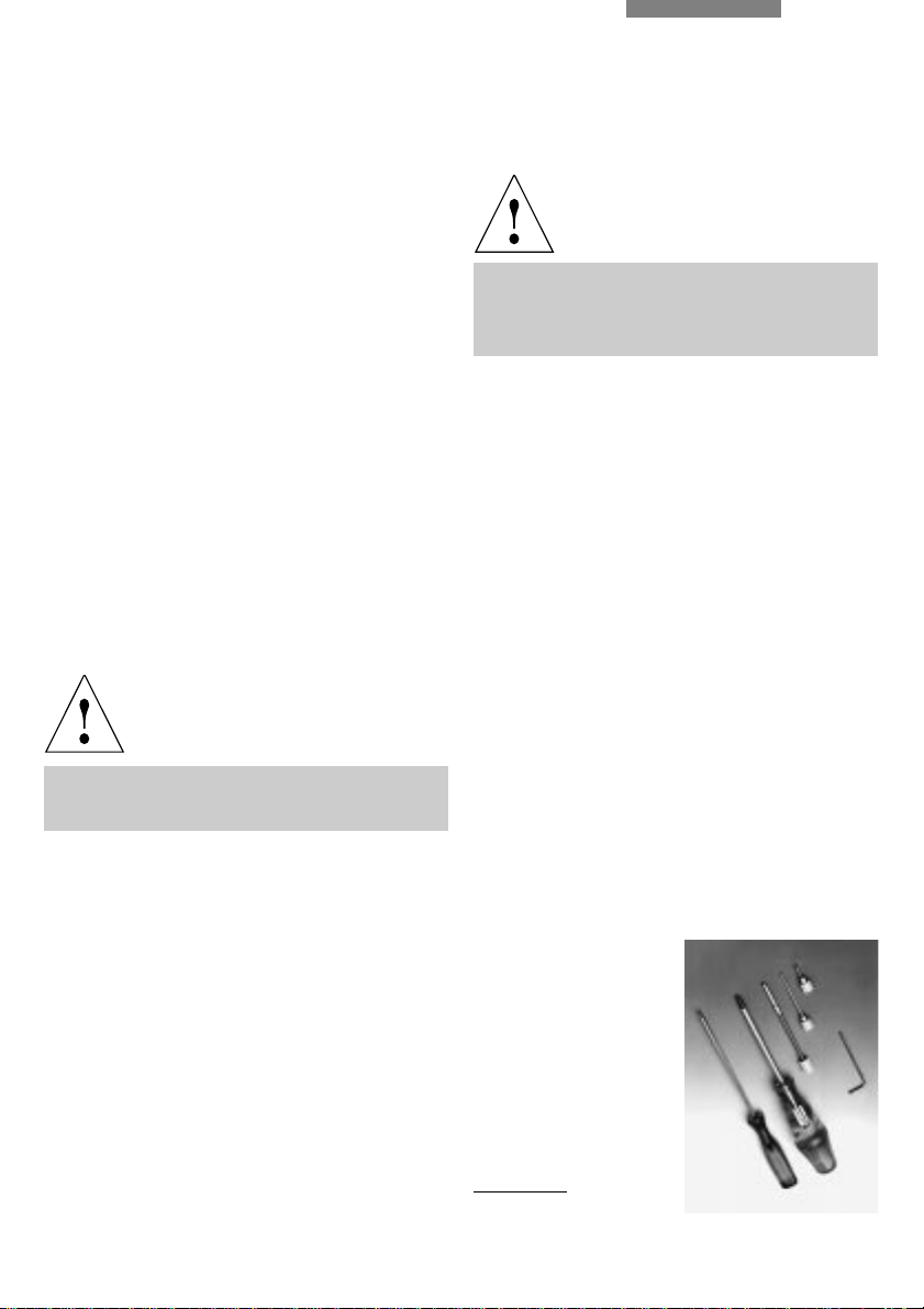
Wearing and spare parts, tools ....................... 112
Index ..................................................................... 113
EU-Conformity declaration ............................... 114
General specifications
Mains voltage: 100–115 V/230 V, ±10%
(E focus)
90 –250V
(mech.focus)
Frequency: 50– 160 Hz ~
Power consumption: max. 160 W
Use: indoors only
Operating temperature: 10– 36°C
Relative humidity: 0– 80% to 30°C
Overvoltage category: II
Contamination class: 2

6
Transmitted light path*
1Light source (lamphousing not illustrated), 2Filter magazine*, 4-pos., 3Diffusing screen,
4Aperture diaphragm, 5Imaging system of aperture diaphragm, 6Field diaphragm, 7Polarizer*,
8Condenser
Incident light path*
9Light source (lamphousing not illustrated), 10 Filter magazine*, 4-pos.
Diaphragm module with:
11 Aperture diaphragm* or filter and diffusing screen, 12 Field diaphragm, 13 Reflector or filter cube
Imagine light path
14 Objective, 15 Tube optics/Bertrand lens*, 16 Tube, 17 Eyepiece
17
16
14
1
10 9
11
12
13
15
2
34
5
6
7
8
* not part for all outfits

7
Special manuals are supplied with some addi-
tional equipment such as photomicrography,
microscope photometry (MPV), compensators,
heating stages, interference attachments, etc.
There are also extensive brochures on micro-
scopy, which can be ordered, as can extra
copies of this manual, from our agencies for a
cover charge.
Numbers in the text, e.g. 1.2, refer to the illustra-
tions, i.e. Fig. 1, pos. 2 in this example.
Attention:
This manual is an integral part of the product
and must be read carefully before switching
on and using the microscope! It contains
important instructions and information for
safe operation and maintenance of the
product and must therefore be kept in a safe
place!
Special safety information is marked at the
edge by the lefthand symbol and highlighted
by a grey background.
Warning of hot surface.
Attention! This symbol means that incorrect
operation can damage the microscope or its
accessories.
Explanatory note.
Item is not included in all variants of the micro-
scope.
The Leica DMR microscope series consists of
several basic stands and a range of modular
components allowing an almost unlimited
variety of individual outfits.
Therefore this manual has been given a modular
layout as well to show you other possible
configurations besides your own.
The manual is divided into two main chapters:
Assembly (including a brief description of each
component) and
Operation.
Any alterations or additional information are
described on extra pages. There is a
supplementary manual for the automatic
version. The manuals are multilingual. Due to
the spiral binding you can turn the language you
want to the front. The manual can be filed in the
supplied folder with the transparent plastic
tongues.
Important notes on this manual
*
!
Text symbols and their meaning:

8
Attention:
Fire hazard! Keep lamphousings at least
10 cm (4˝) away from inflammable objects
such as curtains, wallpaper or books!
Assembly tools
You only need a few ordinary screwdrivers to
assemble your microscope. These are supplied
with the delivery. Replacements for lost tools
can be obtained from us or from a tool shop
(Fig. 1), see list of spare parts on p. 112.
Unpacking
Please compare the delivery carefully with the
packing note, delivery note or invoice. We
strongly recommend that you keep a copy of these
documents with the manual, so that you have
information on the time and scope of delivery
later when ordering more equipment or when
the microscope is serviced. Make sure that no
small parts are left in the packing material.
Some of our packing material has symbols
indicating environmental-friendly recycling.
Attention:
When taking the microscope out of its packing
and putting it onto the desk take care not to
damage the sensitive vibration-damping feet on
the bottom of the microscope.
Attention:
Do not connect the microscope and periph-
erals to the mains yet! (see page 53).
Installation site
Attention:
Make sure that the workplace is free from oil
and chemical fumes. Vibrations, direct sunlight
and major temperature deviations have a nega-
tive effect on measurements and photomicro-
graphy. This and an ergonomically designed
chair which can be adjusted in several positions
arethe basicprerequisites forfatigue-free micro-
scopy.
Assembly/General information
!
Fig. 1 Assembly tools
13 mm hexagonal
screwdriver
2Crosstip screwdriver*
3Adjustment key for
Sénarmont compensator*
4Pol centering key (long
version)*
5Centering key (short
version)*
6Allen key 2 mm (3 mm)*
* not part of all outfits
!
12345
6

9
Fig. 2 Back of microscope stand
1RS 232 C* interface, 2Connection for 12V 100 W transmitted
light lamp* , 3Connection for 12 V 100 W incident light lamp*,
4Ground connection, 5Mains connection, 6115/230 V**
switchover, 7Space for extra lamphousing or switchable
mirror, 8Fuses (T4A), 9Lamphousing 106*: screw for opening
lamp housing 106, o
ONot illustrated, on the top surface of the
back of the microscope: plug connection* for photomicro
(lamp and shutter control)
The instruments and accessories described
in the manual have been checked for safety
or possible risks. Before making any altera-
tions to the equipment or combining it with
non-Leica components in a way not de-
scribed in this manual, consult the Leica
agency for your region or the main factory in
Wetzlar! Any guarantee will be rendered in-
valid if the instrument is opened or modified
in any way by unauthorised persons or if the
instrument is used in another way than the
one described in these instructions!
+ 6
-
25 + 6
-
20
9
7
6
5
8
4
2
3
1
Setting the mains voltage
Microscopes with mechanical focusing (42.12)
are automatically adapted to the local mains
voltage in a range of 120 %/230 % V. For
microscopes with motor focus (RE and RXE
models, Fig. 44), however, the selector switch at
the back of the microscope (2.6) must be set.
Attention:
For external power units the mains voltage
should always be set according to the sepa-
rate instructions supplied.
Electric safety
To ensure that the microscope and
accessories are in a perfectly safe condition,
please note the following advice and
warnings: The mains plug must only be
inserted into a grounded outlet. If an
extension cord is used, it must be grounded
as well. Using the ground connection (2.4),
any accessories connected to the
microscope which have their own and/or a
different power supply can be given the same
ground conductor potential. Please consult
our servicing personnel if you intend to
connect units without a ground conductor.

10
Fig. 3 Deviating mirrors
1non-switchable deviating mirror, 2Lamp mount without*
mirror for second lamphousing, with clamp screw,
3Switchable deviating mirror*, 4Mount for switch rod,
5Switch rod*
Fuses
Attention:
The two fuses integrated in the mains
connection (2.7: T4A, see spare parts list on
page 112) come into action when the mains
voltage selector is incorrectly set (motor
focus only) or in case of internal electronic
defects. For fuses for external power units
please see the relevant special instruction
manual and spare parts list on page 112. In
the event of repeated fuse failure it is
important to consult our Technical service.
Assembly of light sources
Upto 4 lamphousings can be adapted depending
on the microscope configuration. If only one light
source is used this is normally attached to the
left side of the microscope. Only lamphousing 106
(2.8) and the microflash (see separate instruc-
tions) can be used for transmitted light).
Retrofitting additional light sources
When retrofitting the incident light illuminating
axis the microscope must be equipped with a
deviating mirror (3.1) with lamp mount. If you
want to use 2 light sources alternately in
transmitted and/or incident light, a switchable
deviating mirror (3.3, either manual or motor
controlled) can also be retrofitted.
The non-switchable mirror (3.1) is mounted to
the left, the switchable mirror (3.3) from the
back. To do this, remove the cover (using a
sharp object if necessary), or, if a mirror is
already in place, remove it by loosening the
4 screws.
Hold the mirror you want to fit on the
microscope with the flattened side of the lamp
mount pointing downwards. For switchable
mirrors only: before tightening the screws hold
the mount for the switching rod (3.4) at an angle
of about 45°to the longitudinal axis of the
microscope. Remove the stopper from the hole
(22.4) or (61.7) with the 3 mm hexagonal screw-
driver (1.1).
1
2
3
4
5

11
Insert the switch rod (3.5) into the hole and
screw into the mount (3.4). Screw the lamp
mount
without the mirror (3.2) onto the left of the
microscope.
Motorized mirror only: first fix the holder with
the short screw in the top right drill hole, then fix
the lamp mount with the 3 long screws.
Tighten the 4 screws to fix the lamp mount(s).
Lamphousing 106
only for 12V 100W halogen lamp (centerable in x
and y direction), focusable, two-lens collector.
Without reflector, with grooved diffusing screen,
heat-absorbingfilter, Fig.2.8, Fig.4 and Fig.48.17.
Besides lamphousing 106, the following light
sources can be used for incident light:
Lamphousing 106z
for 12V 100W halogen lamp and gas discharge
lamps up to 100 W (Hg 50, Xe 75, Hg 100 W,
spectral lamps). Like lamphousing 106, without
diffusing screen, but with centerable and
focusable reflector and 4- or 6-lens collector.
Quartz collector on request. Fig. 5 and 48.1.
Lamphousing 252
for gas discharge lamps up to 250 W (Xe 50, Hg
200 W), centerable lamp socket, focusable 4-lens
collector, focusable and centerable reflector. In
preparation.
Microflash
for photography of fast-moving objects. Only in
connection with the electrically switchable
deviating mirror and a lamphousing (see special
instructions).

12
Fig. 4 Lamphousing 106*, opened
112V 100W halogen lamp in holder, 2Collector, 3Diffusing
screen
Lamphousing 106z
Important:
For incident light only (48.1)! Disassembled like
lamphousing 106 (see above).
12 V 100 W halogen lamp
Disconnect from power supply (2.5).
Loosen screws (5.4 and 5.9) with crosstip
screwdriver and flip up lid (5.1).
Pull cut-out plug slightly out of socket (5.11).
Unscrew screws (5.10) on the lamp holder and
pull out the lamp holder (Fig. 6). Remove defect
lamp and insert new 12V 100W halogen lamp.
Attention:
Leave the protective covering on the lamp until it
is in its holder!
Avoid making fingerprints or wipe off
immediately.
Spare lamps
See page 112 for code nos.
Lamphousing 106
Disconnect from power supply (2.5),
disassemble using hexagonal screwdriver (1.1
and 3.2). Unscrew screw (2.9) and remove cover.
Move the collector to the front (48.19).
Remove the defect lamp and put a new
12V 100W halogen lamp into the lamp holder
without tilting (4.1).
Attention:
Leavethe protectivecovering onthe lampuntil it
is in its holder. Avoid making fingerprints on the
lamp or wipe off immediately.
Close the lamphousing (2.9). !
1
2
3
!
!

13
Lamphousing 106z*Hg- and Xe lamps
Attention:
Danger: the following information is
extremely important and should be adhered
to under all circumstances:
Always unplug the power unit from the mains
before assembly work is carried out.
Waitfor the lamphousing to cool down before
opening (at least 15 min.), danger of ex-
p
losion!
Never touch glass parts of the burner with
your hands. Remove any fingerprints or dust
carefully (perhaps using alcohol).
Adjust lamps immediately after ignition (see
page 90 ff.)
Attention:
Avoidswitchingon andofffrequently, as this can
impair the stability of the lamp and shorten its
life.
Hot Hg lamps cannot be reignited until they have
cooled down. We recommend that you let new
burners burn in for several hours without
interruption if possible.
It is a good idea to keep a record of the hours
the lamp is in use and to compare with the
manufacturer’s specifications. Replace dis-
coloured, spent lamps.
We cannot accept any liability for damage
resulting from a lamp explosion.
Attention:
Always wear safety clothing (gloves and face
mask) when assembling Xe burners (danger
of explosion).
Fig. 5 Lamphousing 106z*
1Lid, flipped up, 2Collector, 312 V 100 W halogen lamp with
holder 4, 9 Lid screws, 5Reflector, 6, 8 x/y centering of
reflector, 7Reflector focusing, 10 Screws for lamp socket,
11 Socket for cut-out plug Fig. 6 12 V 100 W lamp holder (LH 106z only)
1
2
3
4
5
6
7
8
9
10 1011
!

14
!Attention:
Protect movable interior parts with foam rubber
or similar in case of shipment.
To openlamphousing106z and 252: undo screws
(5.4) and flip up the lid of the lamphousing. Pull
the cut-out plug slightly out of the socket (6.11).
Undo the screws (5.10) on the lamp holder and re-
move the holder (Fig. 7). Remove the spent burner
by loosening the clamp screws (7.1 and 7.3).
Insert burner as follows, adhering strictly to the
above safety information:
Do not remove the protective covering yet (7.7).
Fig. 7 Lamp holders for gas discharge lamps*
1Upper clamp, 2Seal point of the burner, 3Lower clamp,
4, 6 Drillholes for fixing the holder, 5Sockets for cut-out plug,
7Protective cover
Hg 50
1
2
3
4
5
6
Xe 75
1
3
7
1
3
Hg 100
1
3
Hg 100
Stab.

15
Lamphousing 106z, Hg- and Xe lamps
Attention:
Always insert burner so that
1. the lettering on the metal base is upright
after insertion (different diameters of the
metal base for the Hg 100 and Xe 75 burners
ensure that these are always inserted the
right way up). If one of the bases is labelled
“Up”, it must therefore be assembled at the
top.
2. If the lamp bulb has a seal point (7.2), turn
the burner so that this point will be at the
side, not in the light path.
Apart from the halogen lamp the following gas
discharge lamps can be used, all requiring dif-
ferent lamp holders (Fig. 7) and power units:
Type Average life
Hg ultra high pressure lamp 50 W (alternating current) 100 h
Xe high pressure lamp 75 W (direct current, stabilized) 400 h
Hg ultra high pressure lamp 100 W (direct current, stabilized/non- stabilized) 200 h
Hg ultra high pressure lamp 100 W (direct current, stabilized/
non-stabilized, type 103 W/2) 300 h
Put the upper pin of the burner between the
clamps of the flexible power supply and clamp
with screw (7.1).
Unscrew the stud (7.3) in the holder slightly,
insert the lower end of the metal base and
retighten the stud.
Exchanging the collector on lamphousing 106 z:
Move the collector to the rearmost position with
the focusing knob (48.19). Pull the focusing knob
of the collector outwards. The collector can
now be removed.
Attention:
Make sure that the lamp base and the power
unit have the same number. If the lamp base is
marked L1, for example, L1 must also be set on
the power unit to make full use of the lamp and
not to shorten its life.
Move the collector to the front position with the
focusing knob (48.19).
Attention:
Remove the protective covering from the
burner (7.7).
Put the lamp holder with burner inserted into the
lamphousing and secure with the screws (8.9).
Try moving the collector (48.19): it must not
touch the power lead.
Attention:
When closing the lamphousing make sure that
the pins of the cut-out plug engage in the
sockets (8.8). Retighten the screws of the lid.
Push the cut-out plug in as far as it will go.
Attach the lamphousing to the microscope
(page 16) and connect to the power unit
(compare mains voltage!).
!
!

16
Microflash
The microflash is assembled in the same way
(only in conjunction with the switchable mirror
and a lamphousing).
Ventilation
Attention:
Important: Make sure that the instrument has
sufficient ventilation:
Take care not to block the air supply
underneath the microscope and at the con-
nected lamphousings or the air vents on the
top of the microscope with paper, etc. Fire
hazard! Minimum distance from inflammable
objects 10 cm (4˝).
Lamphousing 106, 106z
Attention:
Only lamhousing 106 (48.1) can be used for
transmitted light!
Remove the dust protection cover from the lamp
mount. Unscrew the clamp screw (3.2) with the
aid of the hexagonal screwdriver (1.1) so that the
screw on the inner surface of the lamp mount
does not protrude above the surface. Align the
lamphousing so that the screw engages in the
corresponding indentation on the lamphousing.
Tighten the screw to fix the lamphousing firmly
to the microscope.
Filter mount
A filter mount (Fig. 9) taking up to four extra
filters (50 mm diameter) can be assembled
between the microscope and the lamphousing
inthe sameway. Whenlamphousing106 isused,
only 1 thick or 2 thin filters can be inserted.
Fig. 8 Lamphousing 106 z with Hg 50 burner
1Lid, 2Collector, 3Burner (Hg 50), 4Reflector, 5, 7 x/y
adjustment of the reflector, 6Reflector focusing, 8Sockets for
safety cut-out plug, 9Lamp holder screws
1
2
3
4
5
6
7
8
9
9
!

17
Filter holder*/lamphousing
Filters with a diameter of 50 mm can be inserted
in the special filter holder (accessory, Fig. 9)
next to the lamphousing or in the microflash, or
placed on the microscope base (27.3) in
transmitted light.
Microscope base*and condenser*
Filters with a diameter of 32 mm and holders can
also be placed on the microscope base. The
mount on the underneath of the condenser
holder (27.6) should only be used for the
polarizer or whole- or quarter-wave compensa-
tors (57a,1 and 2).
Filters situated between the microscope base
and the condenser may cause disturbing
reflections (this may be remedied by slightly
tilting the filter) and lead to strain birefringence
in polarized light and ICT.
Filter magazine*
The best way to accommodate filters is there-
fore in the filter magazine (Fig. 10, 42.8 and 42.15):
Loosen the 2 fixing screws to remove the filter
magazine. It is easier to remove if the four
controls are operated. Put the filters into the
slots (without holders!) and tighten the clamp
screw. Always put the diffusing screen in the
position nearest the lamp. Put the label caps
(10.3) onto the corresponding switch rods and
align the lettering.
The filter magazine is more easily replaced if all
4filters are tiltedto oneside firstby pressingthe
buttons. Finally, check that all 4 filters can be
switched in and out smoothly and tighten the
fixingscrews.If thickfilters getstuck, try putting
them in a different slot or altering their position
in the slot.
Interference filters must be inserted with the
bright reflecting side towards the light source!
1
2
3
Fig. 9 Filter holder (intermediate unit), with lamphousing for
max. 4 filters, dia. 50 mm (when lamphousing 106 is used, only
1 thick or 2 thin filters can be inserted)
Fig. 10 Filter magazine T/R (for transmitted and incident light,
Figs. 42.8 and 42.15), also available with only 1 pos.
1Filter holder (Ø 32 mm, non-mounted), 2Clamp screw for
filter, 3Switch rod with push-on label caps

18
Mechanical stages*no. 1187 and 1189
Size of stage plate 200 mm x 159 mm, movement
range of object guide 76 mm x 46 mm, with 0.1°
verniers for registration of specimen coordi-
nates. Removable specimen holder.
Up to 110°stage rotation, clampable. Vertically
adjustable coaxial drive for specimen positioning.
Maximum specimen weight 4 kg.
Stage clearance 25 mm for fixed stage, 63 mm
for interchangeable stage. 2 M4 drill holes for
attachment of heating stages.
The 1187 stage (Fig. 11) is especially designed
for transmitted light and fluorescence micro-
scopy, whereas the similar 1189 stage is for
incident light microscopy (i.e. for thicker and
heavier samples; shorter coaxial drives and
sample holder without spring clip), but also for
transmitted light microscopy.
Stage no. 1086 U*
with inverted stage bracket, for incident light
only. Size: 160 x 150 mm, stage clearance: 123 mm.
Object guide no. 12* can be adapted.
Rotary Pol stage*
Precision stage on ball bearings, stage diameter
179 mm, 360°scale division and 2 verniers
reading to 0.1°, 45°clickstops, can be activated in
any
azimuth, Fig. 13. 3 M4 drill holes for attach-
ment of heating stages, object guide, etc.,
Fig. 13.
Pol3 adaptableobject guidefor specimenformats
25 mm x 46 mm, 25 mm x 75 mm, 50 mm x 50 mm.
Interchangeable control knobs with clickstops
at 0.1, 0.3, 0.5, and 2 mm object displacement in
x and y direction.
Other stage variants are adaptable besides
these standard models, e.g. the SCOPOSCAN
scanning stage.

19
Only for microscopes with interchangeable stage
Assemble the condenser holder* (12.10) first
(see page 20). Loosen the stage clamp (12.1) and
hold stage against the dovetail guide (12.4).
Screwing the stage clamp only slightly, align the
stage for specimens up to a thickness of about
1.3 mm (transmitted light specimens) so that the
top end of the dovetail guide is flush with the top
end of the stage clamp. For thicker specimens
(incident light) and heating stages the stage is
clamped lower down.
Then clamp the stage tightly, as otherwise it may
tilt slightly when a heavy load is placed on it.
Only for microscopes with fixed stage
The stage is protected against transit damage
by 2 foam blocks (Fig. 11). Push out the upper
block first. To remove the lower block, move the
coarse drive* (42.12) slightly. The block can then
be pushed out at the side.
Attention:
If the microscope has a motor focus:
after switching on the microscope* (42.14) tip
coarse focusing “Up” (44.2, page 58) 1–3 times
to make the stage move upwards slightly. The
foam block can then be removed at the side.
Keep the foam blocks in case the microscope
needs to be transported again, as long periods
of vibration lead to damage!
!
Fig. 11 Transit protection for microscopes with fixed stage*
Fig. 12 Assembly of condenser holder* and specimen stage*
1Stage clamp, 2Drill hole for clamping the condenser holder
(3 mm hexagonal screwdriver), 3Condenser height adjust-
ment, 4Dovetail guide, 5Adjustable upper stop of condenser,
6Stage rotation clamp (no. 1187 and 1189), 7Universal
condenser with disc, 8Centering screws for light rings/
IC prisms, 9Lever for condenser top, 10 Condenser holder
(with slot for whole- and quarter-wave compensators)
1
2
3
4
6
7
8
9
10
5
This manual suits for next models
5
Table of contents
Other Leica Microscope manuals

Leica
Leica TCS SP5 X User manual

Leica
Leica ICC50 E User manual

Leica
Leica SP8 AT CIAN Parts list manual

Leica
Leica DIGILUX 1 User manual

Leica
Leica DM LM Reference guide

Leica
Leica ATC 2000 User manual

Leica
Leica WILD M695 User manual

Leica
Leica BF200 User manual

Leica
Leica TCS SP8 MP User manual

Leica
Leica DM2000 User manual